Page 346 of 3342

Crank pin and crank journalOut-of-roundness 0.020 mm (0.0008 in) or less
Grinding limit 0.25 mm (0.0098 in)
Crank pin outer diameterSTD 47.984—48.000 mm (1.")
CrankshaftBend limit 0.035 mm (0.0014 in)
Crank pin and crank journalOut-of-roundness 0.020 mm (0.0008 in) or less
Grinding limit 0.25 mm (0.0098 in)
Crank pin outer diameterSTD 47.984—48.000 mm (1.8891—1.8898 in)
0.03 mm
(0.0012 in)
US47.954—47.970 mm (1.8879—1.8886 in)
0.05 mm
(0.0020 in)
US47.934—47.950 mm (1.8872—1.8878 in)
0.25 mm
(0.0098 in)
US47.734—47.750 mm (1.8793—1.8799 in)
Crank journal outer diameter#1, #5STD 59.992—60.008 mm (2.3619—2.3625 in)
0.03 mm
(0.0012 in)
US59.962—59.978 mm (2.3607—2.3613 in)
0.05 mm
(0.0020 in)
US59.942—59.958 mm (2.3599—2.3605 in)
0.25 mm
(0.0098 in)
US59.742—59.758 mm (2.3520—2.3527 in)
#2, #3, #4STD 59.992—60.008 mm (2.3619—2.3625 in)
0.03 mm
(0.0012 in)
US59.962—59.978 mm (2.3607—2.3613 in)
0.05 mm
(0.0020 in)
US59.942—59.958 mm (2.3599—2.3605 in)
0.25 mm
(0.0098 in)
US59.742—59.758 mm (2.3520—2.3527 in)
Thrust clearanceSTD 0.030—0.115 mm (0.0012—0.0045 in)
Limit 0.25 mm (0.0098 in)
Oil clearance#1, #5 STD 0.003—0.030 mm (0.0001—0.0012 in)
#2, #3, #4 STD 0.010—0.033 mm (0.0004—0.0013 in)
#1, #3, #5 Limit 0.040 mm (0.0016 in)
#2, #4 Limit 0.045 mm (0.0018 in)
Crankshaft
bearingCrankshaft bearing thickness#1, #5STD 1.998—2.011 mm (0.0787—0.0792 in)
0.03 mm
(0.0012 in)
US2.017—2.020 mm (0.0794—0.0795 in)
0.05 mm
(0.0020 in)
US2.027—2.030 mm (0.0798—0.0799 in)
0.25 mm
(0.0098 in)
US2.127—2.130 mm (0.0837—0.0839 in)
#2, #3, #4STD 2.000—2.013 mm (0.0787—0.0793 in)
0.03 mm
(0.0012 in)
US2.019—2.022 mm (0.0795—0.0796 in)
0.05 mm
(0.0020 in)
US2.029—2.032 mm (0.0799—0.0800 in)
0.25 mm
(0.0098 in)
US2.129—2.132 mm (0.0838—0.0839 in)
STD: Standard US: Undersize
5
2-3bSPECIFICATIONS AND SERVICE DATA
1. Engine
Page 350 of 3342
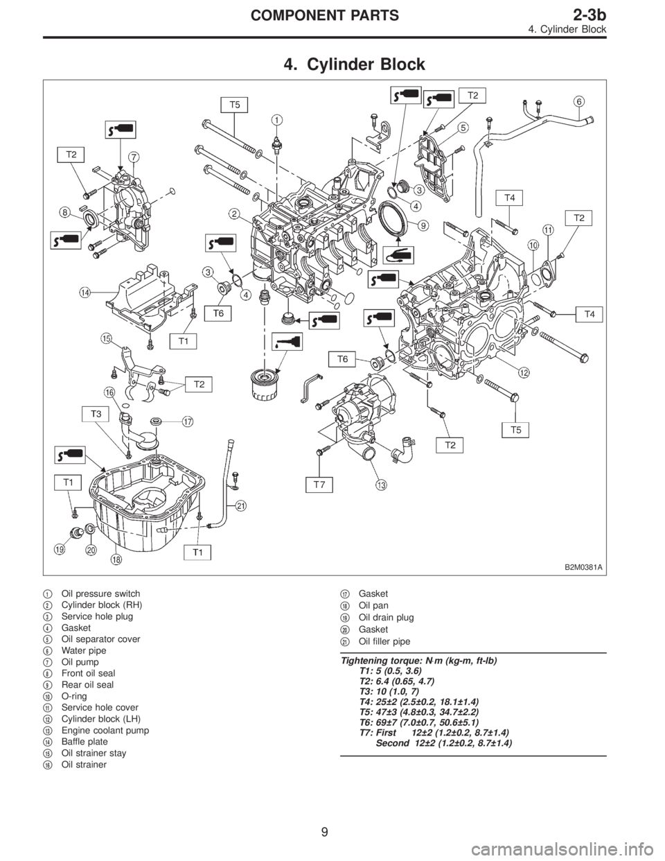
4. Cylinder Block
B2M0381A
�1Oil pressure switch
�
2Cylinder block (RH)
�
3Service hole plug
�
4Gasket
�
5Oil separator cover
�
6Water pipe
�
7Oil pump
�
8Front oil seal
�
9Rear oil seal
�
10O-ring
�
11Service hole cover
�
12Cylinder block (LH)
�
13Engine coolant pump
�
14Baffle plate
�
15Oil strainer stay
�
16Oil strainer�
17Gasket
�
18Oil pan
�
19Oil drain plug
�
20Gasket
�
21Oil filler pipe
Tightening torque: N⋅m (kg-m, ft-lb)
T1: 5 (0.5, 3.6)
T2: 6.4 (0.65, 4.7)
T3: 10 (1.0, 7)
T4: 25±2 (2.5±0.2, 18.1±1.4)
T5: 47±3 (4.8±0.3, 34.7±2.2)
T6: 69±7 (7.0±0.7, 50.6±5.1)
T7: First 12±2 (1.2±0.2, 8.7±1.4)
Second 12±2 (1.2±0.2, 8.7±1.4)
9
2-3bCOMPONENT PARTS
4. Cylinder Block
Page 352 of 3342
G2M0709
1. General Precautions
1) Before disassembling engine, place it on ST3.
ST1 498457000 ENGINE STAND ADAPTER RH
ST2 498457100 ENGINE STAND ADAPTER LH
ST3 499817000 ENGINE STAND
2) All parts should be thoroughly cleaned, paying special
attention to the engine oil passages, pistons and bearings.
3) Rotating parts and sliding parts such as piston, bearing
and gear should be coated with oil prior to assembly.
4) Be careful not to let oil, grease or coolant contact the
timing belt, clutch disc and flywheel.
5) All removed parts, if to be reused, should be reinstalled
in the original positions and directions.
6) Gaskets and lock washers must be replaced with new
ones. Liquid gasket should be used where specified to
prevent leakage.
7) Bolts, nuts and washers should be replaced with new
ones as required.
8) Even if necessary inspections have been made in
advance, proceed with assembly work while making
rechecks.
11
2-3bSERVICE PROCEDURE
1. General Precautions
Page 353 of 3342
2. Timing Belt
A: REMOVAL
1. CRANKSHAFT PULLEY AND BELT COVER
B2M1215A
G2M0711
1) Remove V-belt cover, V-belt and air conditioning com-
pressor drive belt tensioner.
2) Remove pulley bolt. To lock crankshaft, use ST.
ST 499977100 CRANKSHAFT PULLEY WRENCH
3) Remove crankshaft pulley.
B2M0729
4) Remove left-hand belt cover.
12
2-3bSERVICE PROCEDURE
2. Timing Belt
Page 354 of 3342
B2M0730
5) Remove right-hand belt cover.
B2M0731
6) Remove front belt cover.
13
2-3bSERVICE PROCEDURE
2. Timing Belt
Page 355 of 3342
2. TIMING BELT
B2M0685A
G2M0713
B2M0686A
1) If alignment mark and/or arrow mark (which indicates
rotation direction) on timing belt fade away, put new marks
before removing timing belt as follows:
(1) Turn crankshaft using ST, and align alignment
marks on crankshaft sprocket, left-hand intake cam-
shaft sprocket, left-hand exhaust camshaft sprocket,
right-hand intake camshaft sprocket and right hand
exhaust camshaft sprocket with notches of belt cover
and cylinder block.
ST 499987500 CRANKSHAFT SOCKET
14
2-3bSERVICE PROCEDURE
2. Timing Belt
Page 356 of 3342
B2M0687A
(2) Using white paint, put alignment and/or arrow
marks on timing belts in relation to the sprockets.
Z
1: 54.5 tooth length
Z
2: 51 tooth length
Z
3: 28 tooth length
B2M0688
B2M0689
G2M0739
2) Loosen tensioner adjuster mounting bolts.
3) Remove belt idler.
B2M0733
4) Remove timing belt.
5) Remove belt idler No. 2.
CAUTION:
After timing belt has been removed, never rotate intake
and exhaust, camshaft sprocket.
If camshaft sprocket is rotated, the intake and exhaust
valve heads strike together and valve stems are bent.
15
2-3bSERVICE PROCEDURE
2. Timing Belt
Page 357 of 3342
3. BELT TENSIONER AND IDLER
B2M0690A
B2M0732
1) Remove belt idler.
B2M0733
2) Remove belt idler No. 2.
B2M0734
3) Remove belt tensioner and spacer.
16
2-3bSERVICE PROCEDURE
2. Timing Belt
 Before disassembling engine, place it on ST3.
ST1 498457000 ENGINE STAND ADAPTER RH
ST2 498457100 ENGINE STAND ADAPTER LH
ST3 499817000 ENGINE STAND
2) All parts shou")
![SUBARU LEGACY 1997 Service Repair Manual 2. Timing Belt
A: REMOVAL
1. CRANKSHAFT PULLEY AND BELT COVER
B2M1215A
G2M0711
1) Remove V-belt cover, V-belt and air conditioning com-
pressor drive belt tensioner. <Ref. to 1-5 [01A0].>
2) Remove pu](/manual-img/17/57434/w960_57434-352.png "SUBARU LEGACY 1997 Service Repair Manual 2. Timing Belt
A: REMOVAL
1. CRANKSHAFT PULLEY AND BELT COVER
B2M1215A
G2M0711
1) Remove V-belt cover, V-belt and air conditioning com-
pressor drive belt tensioner. <Ref. to 1-5 [01A0].>
2) Remove pu")
 Remove right-hand belt cover.
B2M0731
6) Remove front belt cover.
13
2-3bSERVICE PROCEDURE
2. Timing Belt")
 If alignment mark and/or arrow mark (which indicates
rotation direction) on timing belt fade away, put new marks
before removing timing belt as follows:
(1)")
 Using white paint, put alignment and/or arrow
marks on timing belts in relation to the sprockets.
Z
1: 54.5 tooth length
Z
2: 51 tooth length
Z
3: 28 tooth length
B2M0688
B2M0689
G2M0739")
 Remove belt idler.
B2M0733
2) Remove belt idler No. 2.
B2M0734
3) Remove belt tensioner and spacer.
16
2-3bSERVICE PROCEDURE
2. Timing Belt")