Page 2842 of 3342
B4M0793A
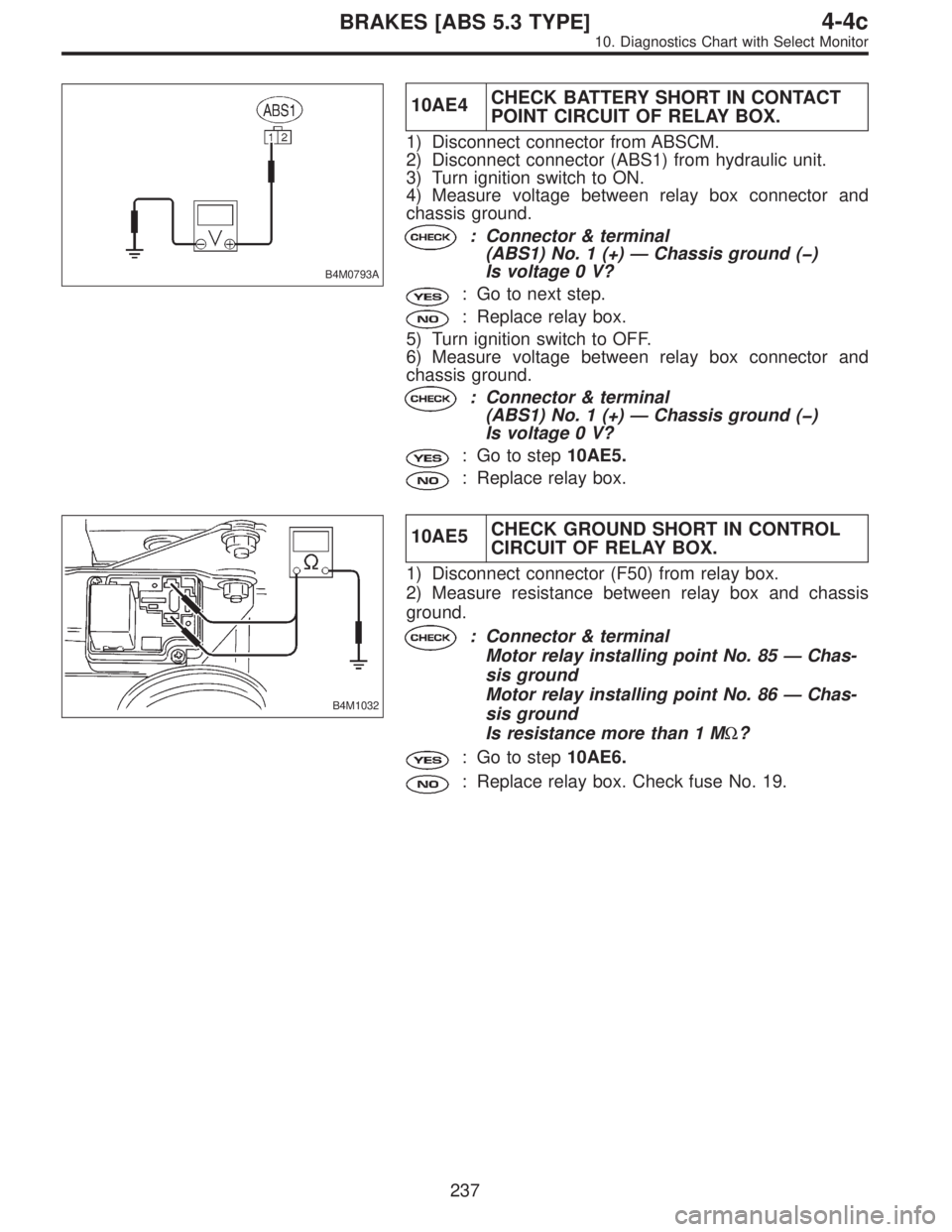
10AE4CHECK BATTERY SHORT IN CONTACT
POINT CIRCUIT OF RELAY BOX.
1) Disconnect connector from ABSCM.
2) Disconnect connector (ABS1) from hydraulic unit.
3) Turn ignition switch to ON.
4) Measure voltage between relay box connector and
chassis ground.
: Connector & terminal
(ABS1) No. 1 (+)—Chassis ground (�)
Is voltage 0 V?
: Go to next step.
: Replace relay box.
5) Turn ignition switch to OFF.
6) Measure voltage between relay box connector and
chassis ground.
: Connector & terminal
(ABS1) No. 1 (+)—Chassis ground (�)
Is voltage 0 V?
: Go to step10AE5.
: Replace relay box.
B4M1032
10AE5CHECK GROUND SHORT IN CONTROL
CIRCUIT OF RELAY BOX.
1) Disconnect connector (F50) from relay box.
2) Measure resistance between relay box and chassis
ground.
: Connector & terminal
Motor relay installing point No. 85—Chas-
sis ground
Motor relay installing point No. 86—Chas-
sis ground
Is resistance more than 1 MΩ?
: Go to step10AE6.
: Replace relay box. Check fuse No. 19.
237
4-4cBRAKES [ABS 5.3 TYPE]
10. Diagnostics Chart with Select Monitor
Page 2843 of 3342
B4M0900A
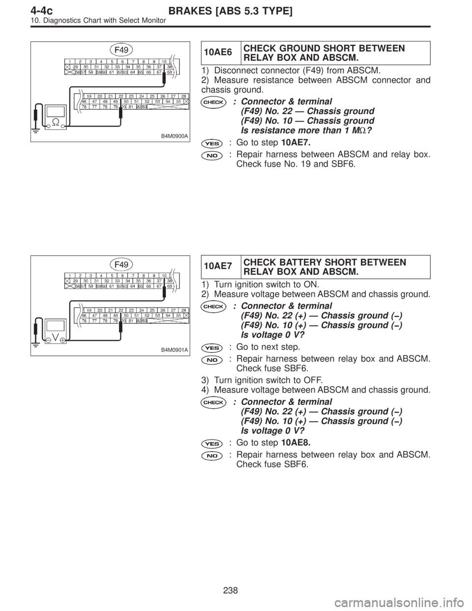
10AE6CHECK GROUND SHORT BETWEEN
RELAY BOX AND ABSCM.
1) Disconnect connector (F49) from ABSCM.
2) Measure resistance between ABSCM connector and
chassis ground.
: Connector & terminal
(F49) No. 22—Chassis ground
(F49) No. 10—Chassis ground
Is resistance more than 1 MΩ?
: Go to step10AE7.
: Repair harness between ABSCM and relay box.
Check fuse No. 19 and SBF6.
B4M0901A
10AE7CHECK BATTERY SHORT BETWEEN
RELAY BOX AND ABSCM.
1) Turn ignition switch to ON.
2) Measure voltage between ABSCM and chassis ground.
: Connector & terminal
(F49) No. 22 (+)—Chassis ground (�)
(F49) No. 10 (+)—Chassis ground (�)
Is voltage 0 V?
: Go to next step.
: Repair harness between relay box and ABSCM.
Check fuse SBF6.
3) Turn ignition switch to OFF.
4) Measure voltage between ABSCM and chassis ground.
: Connector & terminal
(F49) No. 22 (+)—Chassis ground (�)
(F49) No. 10 (+)—Chassis ground (�)
Is voltage 0 V?
: Go to step10AE8.
: Repair harness between relay box and ABSCM.
Check fuse SBF6.
238
4-4cBRAKES [ABS 5.3 TYPE]
10. Diagnostics Chart with Select Monitor
Page 2848 of 3342
B4M0887A
10AF1CHECK CONTACT POINT OF MOTOR
RELAY.
1) Turn ignition switch to OFF.
2) Remove motor relay from relay box.
3) Connect battery to motor relay terminals No. 85 and No.
86.
4) Measure resistance between motor relay terminals.
: Terminals
No. 30—No. 87
Is resistance less than 0.5Ω?
: Go to next step.
: Replace motor relay.
B4M0888A
5) Disconnect battery from motor relay terminals.
6) Measure resistance between motor relay terminals.
: Terminals
No. 30—No. 87
Is resistance more than 1 MΩ?
: Go to step10AF2.
: Replace motor relay.
B4M0890B
10AF2CHECK INPUT VOLTAGE OF RELAY
BOX.
1) Disconnect connector (F8) from relay box.
2) Measure voltage between relay box connector and
chassis ground.
: Connector & terminal
(F8) No. 2 (+)—Chassis ground (�)
Is voltage 10—13 V?
: Go to step10AF3.
: Repair harness connector between battery and
relay box. Check fuse SBF6.
243
4-4cBRAKES [ABS 5.3 TYPE]
10. Diagnostics Chart with Select Monitor
Page 2877 of 3342
1. Supplemental Restraint System
“Airbag”
Airbag system wiring harness is routed near the ABS
sensor, ABS control module and hydraulic control unit.
CAUTION:
�All Airbag system wiring harness and connectors
are colored yellow. Do not use electrical test equip-
ment on these circuit.
�Be careful not to damage Airbag system wiring har-
ness when servicing the ABS sensor, ABS control
module and hydraulic control unit.
2. Pre-inspection
Before performing diagnostics, check the following items
which might affect ABS problems:
A: MECHANICAL INSPECTION
1. POWER SUPPLY
1) Measure battery voltage and specific gravity of electro-
lyte.
Standard voltage: 12 V, or more
Specific gravity: Above 1.260
2) Check the condition of the main and other fuses, and
harnesses and connectors. Also check for proper ground-
ing.
2. BRAKE FLUID
1) Check brake fluid level.
2) Check brake fluid leakage.
3. BRAKE DRAG
Check brake drag.
4. BRAKE PAD AND ROTOR
Check brake pad and rotor.
5. TIRE SPECIFICATIONS, TIRE WEAR AND AIR
PRESSURE
Check tire specifications, tire wear and air pressure.
to 4-2 [S1A1], 4-2 [S1A2].>
2
4-4dBRAKES [ABS 5.3i TYPE]
1. Supplemental Restraint System“Airbag”- 2. Pre-inspection
Page 2878 of 3342
1. Supplemental Restraint System
“Airbag”
Airbag system wiring harness is routed near the ABS
sensor, ABS control module and hydraulic control unit.
CAUTION:
�All Airbag system wiring harness and connectors
are colored yellow. Do not use electrical test equip-
ment on these circuit.
�Be careful not to damage Airbag system wiring har-
ness when servicing the ABS sensor, ABS control
module and hydraulic control unit.
2. Pre-inspection
Before performing diagnostics, check the following items
which might affect ABS problems:
A: MECHANICAL INSPECTION
1. POWER SUPPLY
1) Measure battery voltage and specific gravity of electro-
lyte.
Standard voltage: 12 V, or more
Specific gravity: Above 1.260
2) Check the condition of the main and other fuses, and
harnesses and connectors. Also check for proper ground-
ing.
2. BRAKE FLUID
1) Check brake fluid level.
2) Check brake fluid leakage.
3. BRAKE DRAG
Check brake drag.
4. BRAKE PAD AND ROTOR
Check brake pad and rotor.
5. TIRE SPECIFICATIONS, TIRE WEAR AND AIR
PRESSURE
Check tire specifications, tire wear and air pressure.
to 4-2 [S1A1], 4-2 [S1A2].>
2
4-4dBRAKES [ABS 5.3i TYPE]
1. Supplemental Restraint System“Airbag”- 2. Pre-inspection
Page 2888 of 3342
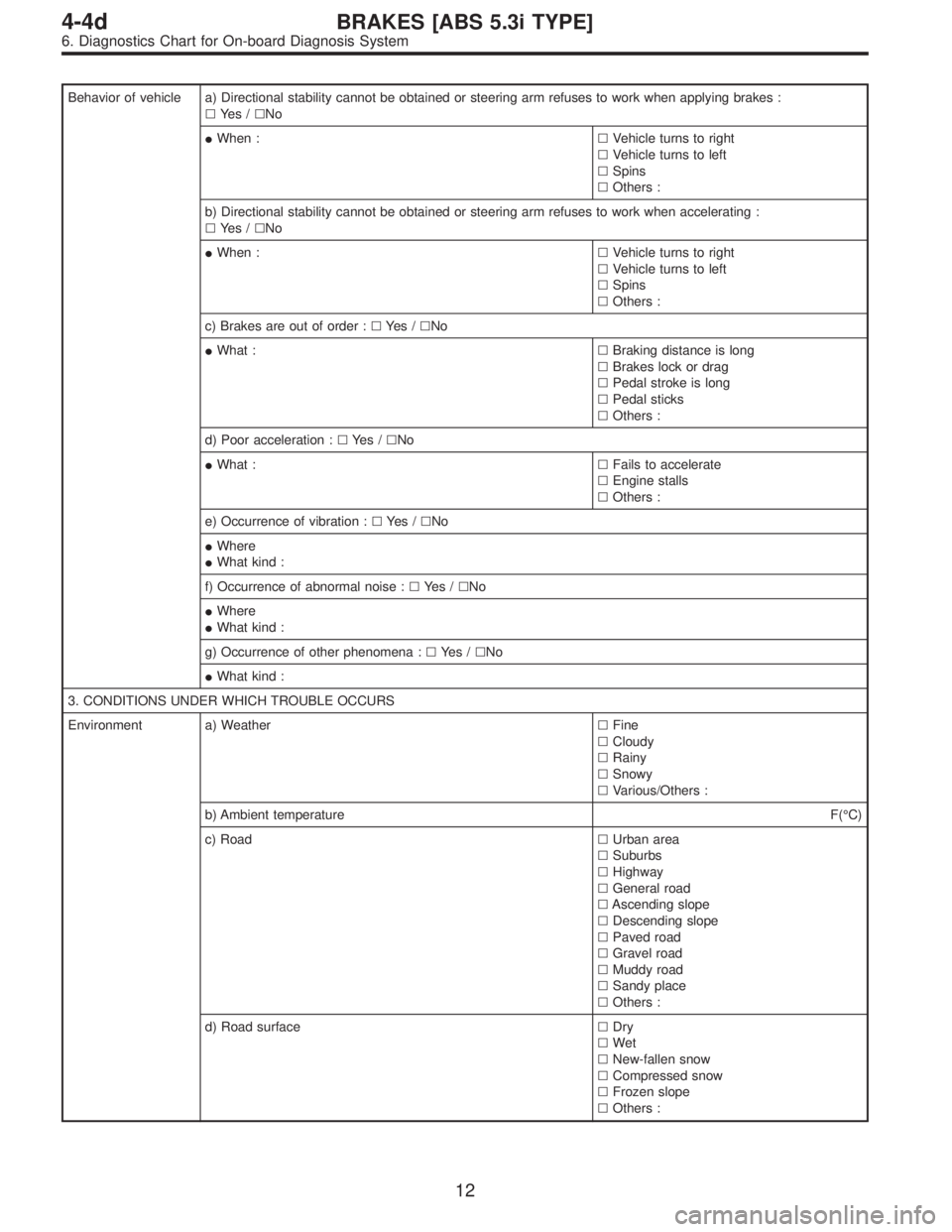
Behavior of vehicle a) Directional stability cannot be obtained or steering arm refuses to work when applying brakes :
�Ye s /�No
�When :�Vehicle turns to right
�Vehicle turns to left
�Spins
�Others :
b) Directional stability cannot be obtained or steering arm refuses to work when accelerating :
�Ye s /�No
�When :�Vehicle turns to right
�Vehicle turns to left
�Spins
�Others :
c) Brakes are out of order :�Ye s /�No
�What :�Braking distance is long
�Brakes lock or drag
�Pedal stroke is long
�Pedal sticks
�Others :
d) Poor acceleration :�Ye s /�No
�What :�Fails to accelerate
�Engine stalls
�Others :
e) Occurrence of vibration :�Ye s /�No
�Where
�What kind :
f) Occurrence of abnormal noise :�Ye s /�No
�Where
�What kind :
g) Occurrence of other phenomena :�Ye s /�No
�What kind :
3. CONDITIONS UNDER WHICH TROUBLE OCCURS
Environment a) Weather�Fine
�Cloudy
�Rainy
�Snowy
�Various/Others :
b) Ambient temperatureF(°C)
c) Road�Urban area
�Suburbs
�Highway
�General road
�Ascending slope
�Descending slope
�Paved road
�Gravel road
�Muddy road
�Sandy place
�Others :
d) Road surface�Dry
�Wet
�New-fallen snow
�Compressed snow
�Frozen slope
�Others :
12
4-4dBRAKES [ABS 5.3i TYPE]
6. Diagnostics Chart for On-board Diagnosis System
Page 2943 of 3342
B4M1256A
8W1CHECK INPUT VOLTAGE OF
ABSCM&H/U.
1) Turn ignition switch to OFF.
2) Disconnect connector from ABSCM&H/U.
3) Turn ignition switch to ON.
4) Measure voltage between ABSCM&H/U connector and
chassis ground.
Connector & terminal
(F49) No. 25 (+)—Chassis ground (�):
: Is the voltage between 10 V and 15 V?
: Go to step8W2.
: Repair harness/connector between battery and
ABSCM&H/U and check fuse SBF6.
B4M1257A
8W2
CHECK GROUND CIRCUIT OF MOTOR.
1) Turn ignition switch to OFF.
2) Measure resistance between ABSCM&H/U connector
and chassis ground.
Connector & terminal
(F49) No. 26—Chassis ground:
: Is the resistance less than 0.5Ω?
: Go to step8W3.
: Repair ABSCM&H/U ground harness.
67
4-4dBRAKES [ABS 5.3i TYPE]
8. Diagnostics Chart with Trouble Code by ABS Warning Light
Page 3029 of 3342
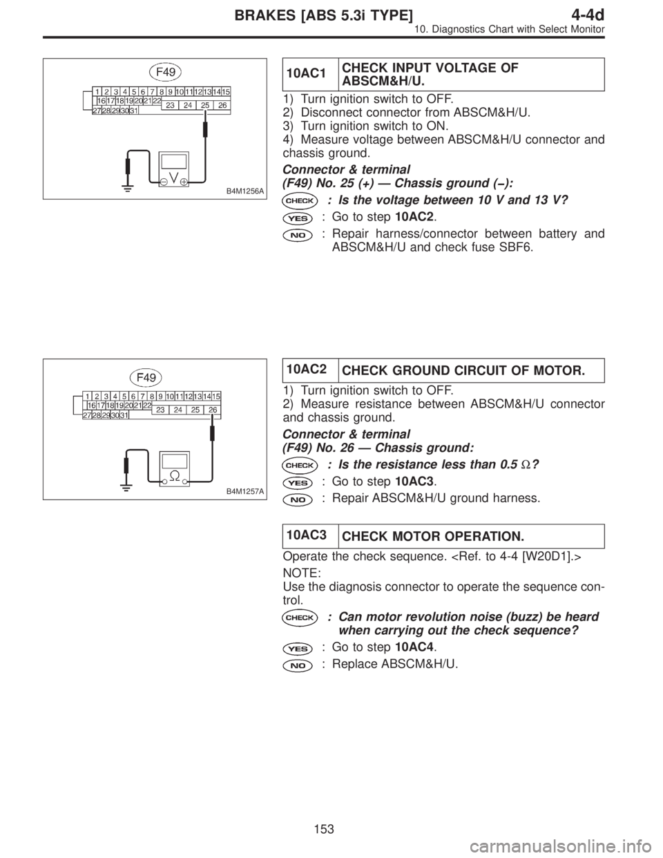
B4M1256A
10AC1CHECK INPUT VOLTAGE OF
ABSCM&H/U.
1) Turn ignition switch to OFF.
2) Disconnect connector from ABSCM&H/U.
3) Turn ignition switch to ON.
4) Measure voltage between ABSCM&H/U connector and
chassis ground.
Connector & terminal
(F49) No. 25 (+)—Chassis ground (�):
: Is the voltage between 10 V and 13 V?
: Go to step10AC2.
: Repair harness/connector between battery and
ABSCM&H/U and check fuse SBF6.
B4M1257A
10AC2
CHECK GROUND CIRCUIT OF MOTOR.
1) Turn ignition switch to OFF.
2) Measure resistance between ABSCM&H/U connector
and chassis ground.
Connector & terminal
(F49) No. 26—Chassis ground:
: Is the resistance less than 0.5Ω?
: Go to step10AC3.
: Repair ABSCM&H/U ground harness.
10AC3
CHECK MOTOR OPERATION.
Operate the check sequence.
NOTE:
Use the diagnosis connector to operate the sequence con-
trol.
: Can motor revolution noise (buzz) be heard
when carrying out the check sequence?
: Go to step10AC4.
: Replace ABSCM&H/U.
153
4-4dBRAKES [ABS 5.3i TYPE]
10. Diagnostics Chart with Select Monitor