Page 3156 of 3342
 Connect select monitor.
2) Start the engine and turn cruise control main switch to
ON.
3) Set select monitor in“FB0”mode.
4) Drive vehicle at least 40 km/h")
2. CRUISE CANCEL CONDITIONS DIAGNOSIS
1) Connect select monitor.
2) Start the engine and turn cruise control main switch to
ON.
3) Set select monitor in“FB0”mode.
4) Drive vehicle at least 40 km/h (25 MPH) with cruise
speed set.
5) If cruise speed is canceled itself (without doing any
cancel operations), a trouble code will appear on select
monitor display.
CAUTION:
�A trouble code will also appear when cruise cancel
is effected by driver. Do not confuse.
�Have a co-worker ride in vehicle to assist in diagno-
sis during driving.
NOTE:
Trouble code will be cleared by turning ignition switch or
cruise control main switch to OFF.
3. REAL-TIME DIAGNOSIS
1) Connect select monitor.
2) Turn ignition switch and cruise control main switch to
ON.
3) Set select monitor in“FA 0”mode.
4) Ensure that normal indication is displayed when con-
trols are operated as indicated below:
�When SET/COAST switch is pressed.
�When RESUME/ACCEL switch is pressed.
�When brake pedal is depressed. (Stop and brake switch
turns ON.)
�When clutch pedal is depressed. (MT model)
�When select lever is set to N position. (AT model)
10
6-2BODY ELECTRICAL SYSTEM
6. Diagnostics Chart for On-board Diagnosis System
Page 3160 of 3342
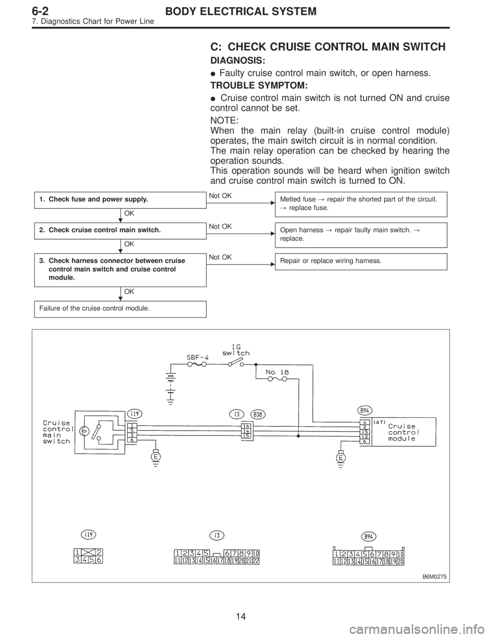
C: CHECK CRUISE CONTROL MAIN SWITCH
DIAGNOSIS:
�Faulty cruise control main switch, or open harness.
TROUBLE SYMPTOM:
�Cruise control main switch is not turned ON and cruise
control cannot be set.
NOTE:
When the main relay (built-in cruise control module)
operates, the main switch circuit is in normal condition.
The main relay operation can be checked by hearing the
operation sounds.
This operation sounds will be heard when ignition switch
and cruise control main switch is turned to ON.
1. Check fuse and power supply.
OK
�Not OK
Melted fuse,repair the shorted part of the circuit.
,replace fuse.
2. Check cruise control main switch.
OK
�Not OK
Open harness,repair faulty main switch.,
replace.
3. Check harness connector between cruise
control main switch and cruise control
module.
OK
�Not OK
Repair or replace wiring harness.
Failure of the cruise control module.
B6M0275
�
�
�
14
6-2BODY ELECTRICAL SYSTEM
7. Diagnostics Chart for Power Line
Page 3161 of 3342
 Check fuse No. 18.
2) Turn ignition switch to ON.
3) Measure voltage between fuse box connector and body.
Connector & terminal / Specified voltage:
(B51) No.")
G6M0181
1. CHECK FUSE AND POWER SUPPLY.
1) Check fuse No. 18.
2) Turn ignition switch to ON.
3) Measure voltage between fuse box connector and body.
Connector & terminal / Specified voltage:
(B51) No. 4—Body / 10 V, or more
B6M0183B
2. CHECK CRUISE CONTROL MAIN SWITCH.
1) Turn ignition switch to OFF.
2) Remove cruise control main switch and disconnect con-
nector.
3) Turn ignition switch to ON.
4) Measure voltage between cruise control main switch
connector and body.
Connector & terminal / Specified voltage:
(i19) No. 3—Body / 10 V, or more
G6M0244
5) Measure resistance between cruise control main switch
terminals.
Terminals / Specified resistance:
No. 3—No. 5 / 10Ω, max. (ON)
1MΩ, min. (OFF)
B6M0184B
3. CHECK HARNESS CONNECTOR BETWEEN
CRUISE CONTROL MAIN SWITCH AND CRUISE
CONTROL MODULE.
1) Connect connector.
2) Turn ignition switch to ON.
3) Turn cruise control main switch to ON.
4) Measure voltage between each terminal of cruise con-
trol main switch or cruise control module and body.
Connector & terminal / Specified voltage:
(i19) No. 3—Body / 10 V, or more
(i19) No. 5—Body / 10 V, or more
(B94) No. 15—Body / 10 V, or more
NOTE:
Depress cruise control main switch with fingers while mea-
suring (i19) No. 5—Body.
15
6-2BODY ELECTRICAL SYSTEM
7. Diagnostics Chart for Power Line
Page 3187 of 3342

2. Basic Diagnostics Procedures
The most important purpose of diagnostics is to determine
which part is malfunctioning quickly, to save time and labor.
A: IDENTIFICATION OF TROUBLE SYMPTOM
Determine what the problem is based on the symptom.
B: PROBABLE CAUSE OF TROUBLE
Look at the wiring diagram and check the system’s circuit.
Then check the switch, relay, fuse, ground, etc.
C: LOCATION AND REPAIR OF TROUBLE
1) Using the diagnostics narrow down the causes.
2) If necessary, use a voltmeter, ohmmeter, etc.
3) Before replacing certain component parts (switch, relay,
etc.), check the power supply, ground, for open wiring
harness, poor connectors, etc. If no problems are
encountered, check the component parts.
D: CONFIRMATION OF SYSTEM OPERATION
After repairing, ensure that the system operates properly.
G6M0206
E: INSPECTION
1. VOLTAGE MEASUREMENT
1) Using a voltmeter, connect the negative lead to a good
ground point or negative battery terminal and the positive
lead to the connector or component terminal.
2) Contact the positive probe of the voltmeter on connec-
tor (A).
The voltmeter will indicate a voltage.
3) Shift the positive probe to connector (B). The voltmeter
will indicate no voltage.
With test set-up held as it is, turn switch ON. The voltme-
ter will indicate a voltage and, at the same time, the light
will come on.
4) The circuit is in good order. If a problem such as a lamp
failing to light occurs, use the procedures outlined above to
track down the malfunction.
8
6-3WIRING DIAGRAM
2. Basic Diagnostics Procedures
Page 3189 of 3342
 Voltmeter method
An open circuit is determined by measuring the voltage
between respective connectors and ground using a
voltmeter, starting with the con")
G6M0208
3. HOW TO DETERMINE AN OPEN CIRCUIT
1) Voltmeter method
An open circuit is determined by measuring the voltage
between respective connectors and ground using a
voltmeter, starting with the connector closest to the power
supply. The power supply must be turned ON so that cur-
rent flows in the circuit. If voltage is not present between a
particular connector and ground, the circuit between that
connector and the previous connector is open.
G6M0209
2) Ohmmeter method
Disconnect all connectors affected, and check continuity in
the wiring between adjacent connectors. When the ohm-
meter indicates“infinite”, the wiring is open.
G6M0210
4. HOW TO DETERMINE A SHORT-CIRCUIT
1) Test lamp method
Connect a test lamp (rated at approximately 3 watts) in
place of the blown fuse and allow current to flow through
the circuit. Disconnect one connector at a time from the
circuit, starting with the one located farthest from the power
supply. If the test lamp goes out when a connector is
disconnected, the wiring between that connection and the
next connector (farther from the power supply) is shorted.
G6M0211
2) Ohmmeter method
Disconnect all affected connectors, and check continuity
between each connector and ground. When ohmmeter
indicates continuity between a particular connector and
ground, that connector is shorted.
10
6-3WIRING DIAGRAM
2. Basic Diagnostics Procedures
Page 3192 of 3342
4. How to Use Wiring Diagram
B6M0213A
A: RELAY
A symbol used to indicate a relay.
B: CONNECTOR-1
The sketch of the connector indicates the one-
pole types.
C: WIRING CONNECTION
Some wiring diagrams are indicated in foldouts
for convenience. Wiring destinations are indi-
cated where necessary by corresponding sym-
bols (as when two pages are needed for clear
indication).
D: FUSE No. & RATING
The“FUSE No. & RATING”corresponds that
used in the fuse box (main fuse box, and joint
box).
E: CONNECTOR-2
1. Each connector is indicated by a symbol.
2. Each terminal number is indicated in the cor-
responding wiring diagram in an abbreviated
form.
3. For example, terminal number“C2”refers to
No. 2 terminal of connector (C:F41) shown in
the connector sketch.
13
6-3WIRING DIAGRAM
4. How to Use Wiring Diagram
Page 3196 of 3342
ABBREVIATION LIST
Abbr. Full name
A.B.S. Antilock Brake System
ACC Accessory
A/C Air Conditioning
AD Auto Down
AT Automatic Transmission
AU Auto Up
+B Battery
DN Down
DRL Daytime Running Light
E Ground
F/B Fuse & Joint Box
FL1.5 Fusible link 1.5 mm
2
IG Ignition
Illumi. Illumination
Abbr. Full name
LH Left Hand
Lo Low
M Motor
M/B Main Fuse Box
MG Magnet
Mi Middle
OP Optional Parts
PASS Passing
RH Right Hand
SBF Slow Blow Fuse
S.M.J. Super Multiple Junction
ST Starter
SW Switch
T.C.S. Traction Control System
UP Up
WASH Washer
17
6-3WIRING DIAGRAM
5. How to Use Super Multiple Junction (S.M.J.)
Page 3199 of 3342

MB-2 Power window circuit breaker
MB-3Engine control module
Fuel pump relay
Main relay
OBD-II service connector
MB-4 A/C relay holder
MB-5 He")
No. Load
MB-1Fuse holder (Rear power supply & seat
heater)
MB-2 Power window circuit breaker
MB-3Engine control module
Fuel pump relay
Main relay
OBD-II service connector
MB-4 A/C relay holder
MB-5 Headlight alarm relay (with security)
MB-6 Headlight LH
MB-7Daytime running light control module
Diode (Lighting)
Diode (Security)
Lighting switch
MB-8Combination meter
Front fog light switch
Headlight RH
Front fog light relay
MB-9Door lock timer
Headlight alarm relay
Interrupt relay
Radio
Security control module
Security indicator light
Spot light
Room light
Step light
Combination meter
Luggage room light
Trailer connector
Trunk room light
MB-10 A/C relay holder
SBF-6ABS relay box
TCS motor relay
SBF-7 TCS valve relay
ALT-1Combination meter
Daytime running light control module
Diode (TCS)
IG Headlight alarm relay
STCruise control module
Engine control module
Inhibitor switch (AT)
Interrupt relay
Starter interlock relay (MT)
FB-1Front washer motor
Rear washer motor
FB-2Engine control module
Main fan relay 1
FB-3Sub fan relay 2
Sub fan motor
FB-4Engine control module
Fuel pump relay
Ignition coil
Transmission control moduleNo. Load
FB-5 ABS relay box
FB-6Side marker light LH
Side marker light RH
FB-7 Door lock timer
FB-9 Hazard switch
FB-10AT shift lock control module
Key warning switch
Power antenna
FB-11 Radio
FB-12 Front accessory power supply
FB-13Mirror heater
Rear power supply relay
Remote control rearview mirror switch
Security control module
Vanity mirror illumination light
FB-14AT shift lock control module
Combination switch
Front wiper motor
Rear wiper motor
Rear wiper relay
FB-15ABS/TCS control module
Transmission control module
FB-16Rear defogger
Rear defogger condenser
Rear defogger switch
FB-17 Rear defogger switch
FB-18AT shift lock control module
Back-up light switch (MT)
Inhibitor switch (AT)
FB-19 Hazard switch
FB-20A/C switch
Combination meter
Mode control panel
TCS off switch
FB-22Blower motor relay
Check connector
Daytime running light control module
Daytime running light relay
FRESH/RECIRC actuator
Hi-beam relay
Power window and sunroof relay
Seat belt timer
FB-23 Airbag control module
FB-24 Airbag control module
FB-25 Lighting switch
20
6-3WIRING DIAGRAM
6. Wiring Diagram