Page 2698 of 3342
B4M0889A
8L3
CHECK SHORT OF MOTOR RELAY.
Measure resistance between motor relay terminals.
: Terminals
No. 85—No. 30
No. 85—No. 87
Is resistance more than 1 MΩ?
: Go to step8L4.
: Replace motor relay.
B4M0890B
8L4CHECK INPUT VOLTAGE OF RELAY
BOX.
1) Disconnect connector (F8) from relay box.
2) Measure voltage between relay box connector and
chassis ground.
: Connector & terminal
(F8) No. 2 (+)—Chassis ground (�)
Is voltage 10—13 V?
: Go to step8L5.
: Repair harness connector between battery and
relay box. Check fuse SBF6.
B4M0891
8L5CHECK INPUT VOLTAGE OF MOTOR
RELAY.
1) Connect connector (F8) to relay box.
2) Measure voltage between relay box and chassis
ground.
: Connector & terminal
Relay installing point No. 87 (+)—Chassis
ground (�)
Is voltage more than 10 V?
: Go to step8L6.
: Replace relay box. Check fuse SBF6.
93
4-4cBRAKES [ABS 5.3 TYPE]
8. Diagnostics Chart with Trouble Code
Page 2699 of 3342

B4M0892A
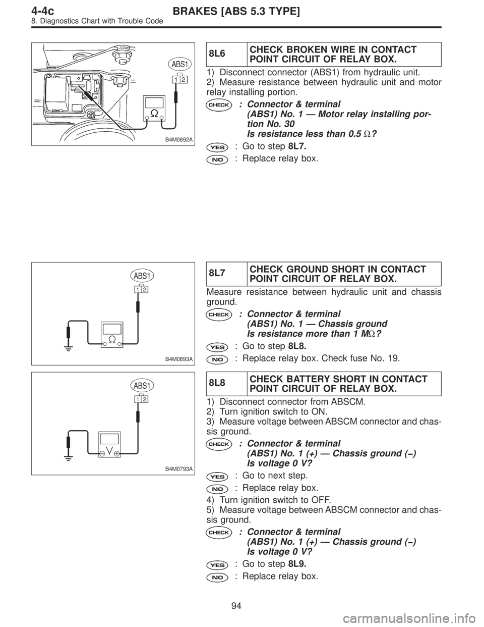
8L6CHECK BROKEN WIRE IN CONTACT
POINT CIRCUIT OF RELAY BOX.
1) Disconnect connector (ABS1) from hydraulic unit.
2) Measure resistance between hydraulic unit and motor
relay installing portion.
: Connector & terminal
(ABS1) No. 1—Motor relay installing por-
tion No. 30
Is resistance less than 0.5Ω?
: Go to step8L7.
: Replace relay box.
B4M0893A
8L7CHECK GROUND SHORT IN CONTACT
POINT CIRCUIT OF RELAY BOX.
Measure resistance between hydraulic unit and chassis
ground.
: Connector & terminal
(ABS1) No. 1—Chassis ground
Is resistance more than 1 MΩ?
: Go to step8L8.
: Replace relay box. Check fuse No. 19.
B4M0793A
8L8CHECK BATTERY SHORT IN CONTACT
POINT CIRCUIT OF RELAY BOX.
1) Disconnect connector from ABSCM.
2) Turn ignition switch to ON.
3) Measure voltage between ABSCM connector and chas-
sis ground.
: Connector & terminal
(ABS1) No. 1 (+)—Chassis ground (�)
Is voltage 0 V?
: Go to next step.
: Replace relay box.
4) Turn ignition switch to OFF.
5) Measure voltage between ABSCM connector and chas-
sis ground.
: Connector & terminal
(ABS1) No. 1 (+)—Chassis ground (�)
Is voltage 0 V?
: Go to step8L9.
: Replace relay box.
94
4-4cBRAKES [ABS 5.3 TYPE]
8. Diagnostics Chart with Trouble Code
Page 2701 of 3342

B4M0895B
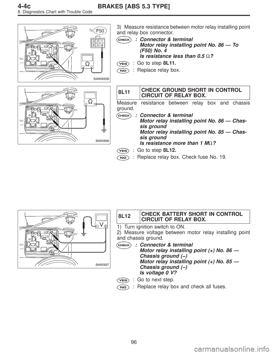
3) Measure resistance between motor relay installing point
and relay box connector.
: Connector & terminal
Motor relay installing point No. 86—To
(F50) No. 4
Is resistance less than 0.5Ω?
: Go to step8L11.
: Replace relay box.
B4M0896
8L11CHECK GROUND SHORT IN CONTROL
CIRCUIT OF RELAY BOX.
Measure resistance between relay box and chassis
ground.
: Connector & terminal
Motor relay installing point No. 86—Chas-
sis ground
Motor relay installing point No. 85—Chas-
sis ground
Is resistance more than 1 MΩ?
: Go to step8L12.
: Replace relay box. Check fuse No. 19.
B4M0897
8L12CHECK BATTERY SHORT IN CONTROL
CIRCUIT OF RELAY BOX.
1) Turn ignition switch to ON.
2) Measure voltage between motor relay installing point
and chassis ground.
: Connector & terminal
Motor relay installing point (+) No. 86—
Chassis ground (�)
Motor relay installing point (+) No. 85—
Chassis ground (�)
Is voltage 0 V?
: Go to next step.
: Replace relay box and check all fuses.
96
4-4cBRAKES [ABS 5.3 TYPE]
8. Diagnostics Chart with Trouble Code
Page 2702 of 3342
3) Turn ignition switch to OFF.
4) Measure voltage between motor relay installing point
and chassis ground.
: Connector & terminal
Motor relay installing point (+) No. 86—
Chassis ground
Motor relay installing point (+) No. 85—
Chassis ground
Is voltage 0 V?
: Go to step8L13.
: Replace relay box and check all fuses.
B4M0898B
8L13CHECK BROKEN WIRE IN MONITOR
SYSTEM HARNESS.
1) Connect between terminals No. 10 and No. 1 of
ABSCM connector (F49) with a lead wire.
2) Measure resistance between relay box connector and
chassis ground.
: Connector & terminal
(F50) No. 6—Chassis ground
Is resistance less than 0.5Ω?
: Go to step8L14.
: Repair harness connector between ABSCM and
relay box.
97
4-4cBRAKES [ABS 5.3 TYPE]
8. Diagnostics Chart with Trouble Code
Page 2703 of 3342
B4M0899A
8L14CHECK BROKEN WIRE IN RELAY CON-
TROL SYSTEM HARNESS.
1) Connect valve relay and motor relay to relay box.
2) Connect connector (F50) to relay box.
3) Connect connector to hydraulic unit.
4) Measure resistance between ABSCM connector and
chassis ground.
: Connector & terminal
(F49) No. 22—Chassis ground
Is resistance 80±10Ω?
: Go to step8L15.
: Repair harness connector between ABSCM and
relay box.
B4M0900A
8L15CHECK GROUND SHORT BETWEEN
RELAY BOX AND ABSCM.
1) Disconnect connector (F50) from relay box.
2) Measure resistance between ABSCM connector and
chassis ground.
: Connector & terminal
(F49) No. 22—Chassis ground
(F49) No. 10—Chassis ground
Is resistance more than 1 MΩ?
: Go to step8L16.
: Repair harness between ABSCM and relay box.
Check fuse No. 19 and SBF6.
98
4-4cBRAKES [ABS 5.3 TYPE]
8. Diagnostics Chart with Trouble Code
Page 2704 of 3342

B4M0901A
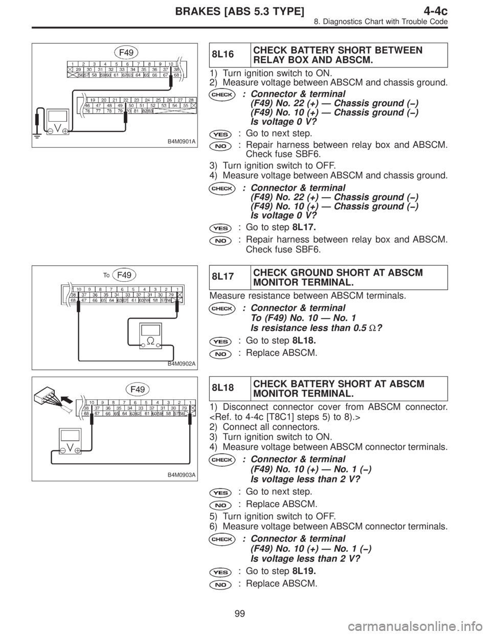
8L16CHECK BATTERY SHORT BETWEEN
RELAY BOX AND ABSCM.
1) Turn ignition switch to ON.
2) Measure voltage between ABSCM and chassis ground.
: Connector & terminal
(F49) No. 22 (+)—Chassis ground (�)
(F49) No. 10 (+)—Chassis ground (�)
Is voltage 0 V?
: Go to next step.
: Repair harness between relay box and ABSCM.
Check fuse SBF6.
3) Turn ignition switch to OFF.
4) Measure voltage between ABSCM and chassis ground.
: Connector & terminal
(F49) No. 22 (+)—Chassis ground (�)
(F49) No. 10 (+)—Chassis ground (�)
Is voltage 0 V?
: Go to step8L17.
: Repair harness between relay box and ABSCM.
Check fuse SBF6.
B4M0902A
8L17CHECK GROUND SHORT AT ABSCM
MONITOR TERMINAL.
Measure resistance between ABSCM terminals.
: Connector & terminal
To (F49) No. 10—No. 1
Is resistance less than 0.5Ω?
: Go to step8L18.
: Replace ABSCM.
B4M0903A
8L18CHECK BATTERY SHORT AT ABSCM
MONITOR TERMINAL.
1) Disconnect connector cover from ABSCM connector.
2) Connect all connectors.
3) Turn ignition switch to ON.
4) Measure voltage between ABSCM connector terminals.
: Connector & terminal
(F49) No. 10 (+)—No.1(�)
Is voltage less than 2 V?
: Go to next step.
: Replace ABSCM.
5) Turn ignition switch to OFF.
6) Measure voltage between ABSCM connector terminals.
: Connector & terminal
(F49) No. 10 (+)—No.1(�)
Is voltage less than 2 V?
: Go to step8L19.
: Replace ABSCM.
99
4-4cBRAKES [ABS 5.3 TYPE]
8. Diagnostics Chart with Trouble Code
Page 2811 of 3342

B4M0861A
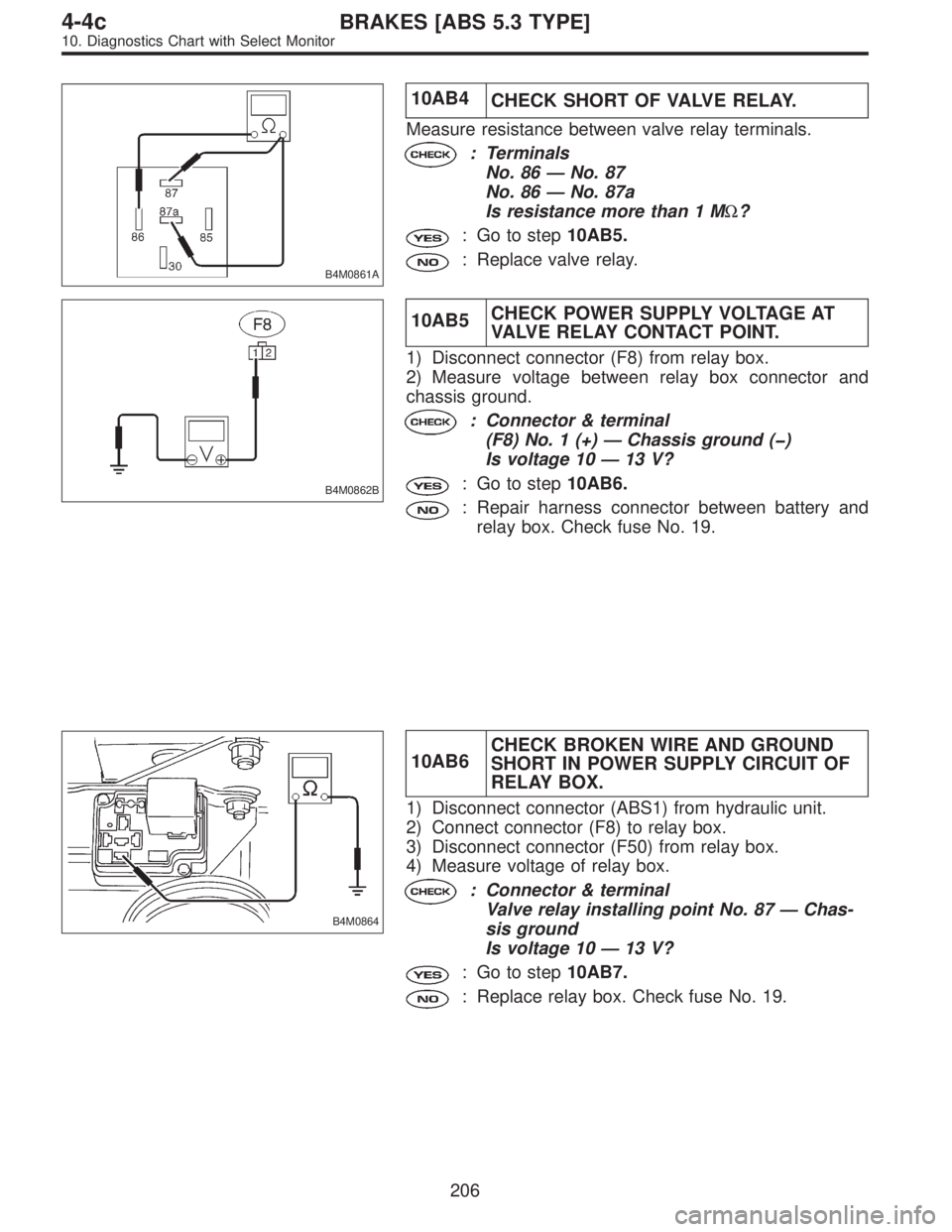
10AB4
CHECK SHORT OF VALVE RELAY.
Measure resistance between valve relay terminals.
: Terminals
No. 86—No. 87
No. 86—No. 87a
Is resistance more than 1 MΩ?
: Go to step10AB5.
: Replace valve relay.
B4M0862B
10AB5CHECK POWER SUPPLY VOLTAGE AT
VALVE RELAY CONTACT POINT.
1) Disconnect connector (F8) from relay box.
2) Measure voltage between relay box connector and
chassis ground.
: Connector & terminal
(F8) No. 1 (+)—Chassis ground (�)
Is voltage 10—13 V?
: Go to step10AB6.
: Repair harness connector between battery and
relay box. Check fuse No. 19.
B4M0864
10AB6CHECK BROKEN WIRE AND GROUND
SHORT IN POWER SUPPLY CIRCUIT OF
RELAY BOX.
1) Disconnect connector (ABS1) from hydraulic unit.
2) Connect connector (F8) to relay box.
3) Disconnect connector (F50) from relay box.
4) Measure voltage of relay box.
: Connector & terminal
Valve relay installing point No. 87—Chas-
sis ground
Is voltage 10—13 V?
: Go to step10AB7.
: Replace relay box. Check fuse No. 19.
206
4-4cBRAKES [ABS 5.3 TYPE]
10. Diagnostics Chart with Select Monitor
Page 2812 of 3342
B4M0865A
10AB7CHECK BROKEN WIRE IN CONTACT
POINT CIRCUIT OF RELAY BOX.
Measure resistance between hydraulic unit connector and
valve relay installing point.
: Connector & terminal
(ABS1) No. 2—Valve relay installing point
No. 30
Is resistance less than 0.5Ω?
: Go to step10AB8.
: Replace relay box.
B4M0866A
10AB8CHECK GROUND SHORT IN CONTACT
POINT CIRCUIT OF RELAY BOX.
Measure resistance between relay box connector and
chassis ground.
: Connector & terminal
(ABS1) No. 2—Chassis ground
Is resistance more than 1 MΩ?
: Go to step10AB9.
: Replace relay box. Check fuse SBF6.
B4M0868B
10AB9
CHECK DIODE OF RELAY BOX.
Measure resistance between relay box connector and
valve relay installing point.
: Connector & terminal
Valve relay installing point No. 30 (+)—To
(F50) No. 2 (�)
Is resistance more than 1 MΩ?
: Go to step10AB10.
: Replace relay box.
207
4-4cBRAKES [ABS 5.3 TYPE]
10. Diagnostics Chart with Select Monitor