Page 1914 of 3342
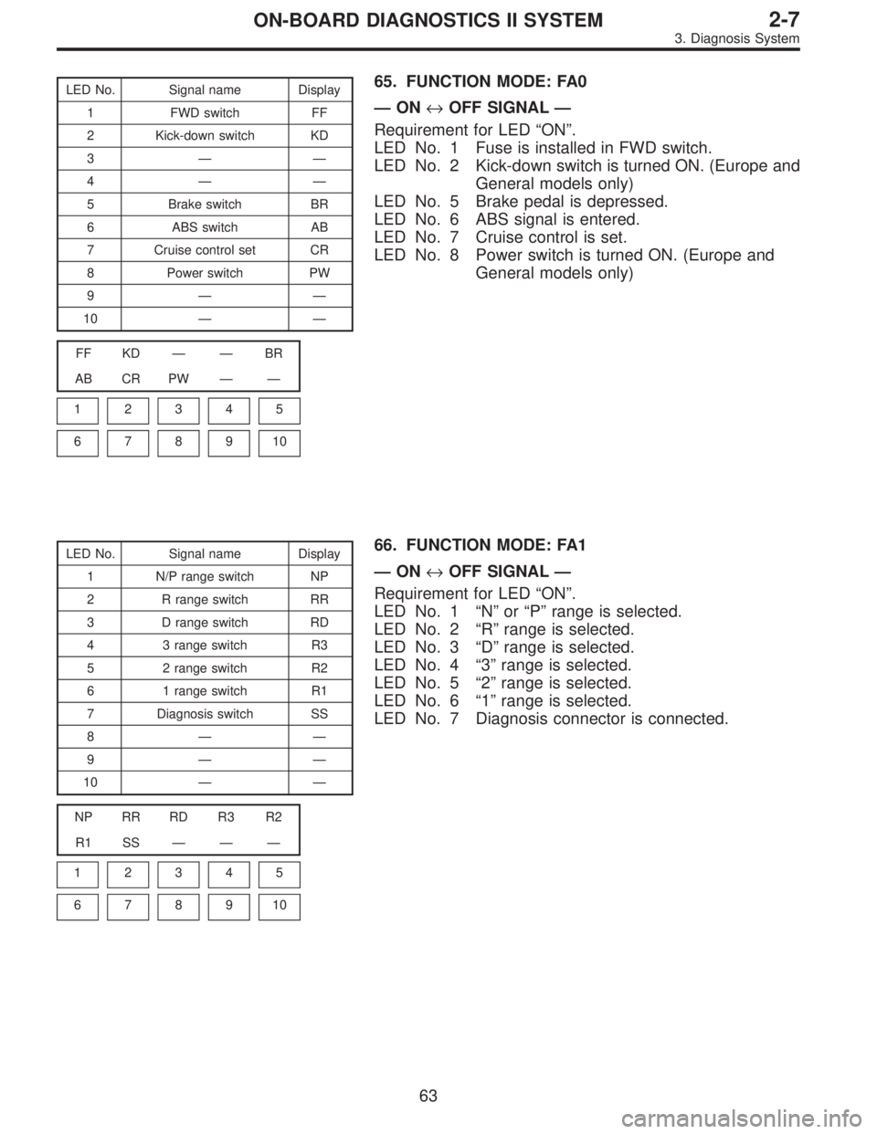
LED No. Signal name Display
1 FWD switch FF
2 Kick-down switch KD
3——
4——
5 Brake switch BR
6 ABS switch AB
7 Cruise control set CR
8 Power switch PW
9——
10——
FF KD——BR
AB CR PW——
1
2345
678910
65. FUNCTION MODE: FA0
—ON↔OFF SIGNAL—
Requirement for LED“ON”.
LED No. 1 Fuse is installed in FWD switch.
LED No. 2 Kick-down switch is turned ON. (Europe and
General models only)
LED No. 5 Brake pedal is depressed.
LED No. 6 ABS signal is entered.
LED No. 7 Cruise control is set.
LED No. 8 Power switch is turned ON. (Europe and
General models only)
LED No. Signal name Display
1 N/P range switch NP
2 R range switch RR
3 D range switch RD
4 3 range switch R3
5 2 range switch R2
6 1 range switch R1
7 Diagnosis switch SS
8——
9——
10——
NP RR RD R3 R2
R1 SS———
1
2345
678910
66. FUNCTION MODE: FA1
—ON↔OFF SIGNAL—
Requirement for LED“ON”.
LED No. 1“N”or“P”range is selected.
LED No. 2“R”range is selected.
LED No. 3“D”range is selected.
LED No. 4“3”range is selected.
LED No. 5“2”range is selected.
LED No. 6“1”range is selected.
LED No. 7 Diagnosis connector is connected.
63
2-7ON-BOARD DIAGNOSTICS II SYSTEM
3. Diagnosis System
Page 1929 of 3342
14) In AT vehicles, do not continue the stall for more than
five seconds at a time (from closed throttle, fully open
throttle to stall engine speed).
15) On ABS or ABS/TCS vehicle, when performing driving
test in jacked-up or lifted-up position, sometimes the warn-
ing light may be lit, but this is not a malfunction of the sys-
tem. The reason for this is the speed difference between
the front and rear wheels. After diagnosis of engine control
system, perform the ABS or ABS/TCS memory clearance
procedure of self-diagnosis system.
[T9K0], or 4-4c [T6D2] or [T9J0], or 4-4d [T6D2] or [T9J0].>
C: PRE-INSPECTION
Before performing diagnostics, check the following items
which might affect engine problems:
1. POWER SUPPLY
1) Measure battery voltage and specific gravity of electro-
lyte.
Standard voltage: 12 V
Specific gravity: Above 1.260
2) Check the condition of the main and other fuses, and
harnesses and connectors. Also check for proper ground-
ing.
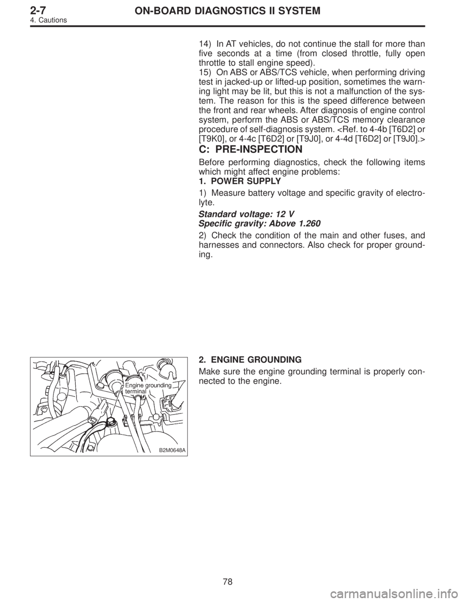
B2M0648A
2. ENGINE GROUNDING
Make sure the engine grounding terminal is properly con-
nected to the engine.
78
2-7ON-BOARD DIAGNOSTICS II SYSTEM
4. Cautions
Page 1934 of 3342
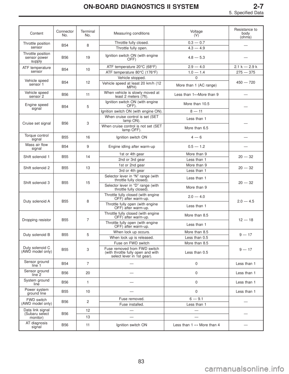
ContentConnector
No.Terminal
No.Measuring conditionsVoltage
(V)Resistance to
body
(ohms)
Throttle position
sensorB54 8Throttle fully closed. 0.3—0.7
—
Throttle fully open. 4.3—4.9
Throttle position
sensor power
supplyB56 19Ignition switch ON (with engine
OFF)4.8—5.3—
ATF temperature
sensorB54 10ATF temperature 20°C(68°F) 2.9—4.0 2.1 k—2.9 k
ATF temperature 80°C (176°F) 1.0—1.4 275—375
Vehicle speed
sensor 1B54 12Vehicle stopped. 0
450—720
Vehicle speed at least 20 km/h (12
MPH)More than 1 (AC range)
Vehicle speed
sensor 2B56 11When vehicle is slowly moved at
least 2 meters (7ft).Less than 1)More than 9—
Engine speed
signalB54 5Ignition switch ON (with engine
OFF).More than 10.5
—
Ignition switch ON (with engine ON). 8—11
Cruise set signal B56 3When cruise control is set (SET
lamp ON).Less than 1
—
When cruise control is not set (SET
lamp OFF).More than 6.5
Torque control
signalB55 16 Ignition switch ON 4—6—
Mass air flow
signalB54 9 Engine idling after warm-up 0.5—1.2—
Shift solenoid 1 B55 141st or 4th gear More than 9
20—32
2nd or 3rd gear Less than 1
Shift solenoid 2 B55 131st or 2nd gear More than 9
20—32
3rd or 4th gear Less than 1
Shift solenoid 3 B55 15Selector lever in“N”range (with
throttle fully closed).Less than 1
20—32
Selector lever in“D”range (with
throttle fully closed).More than 9
Duty solenoid A B55 8Throttle fully closed (with engine
OFF) after warm-up.2.0—4.0
2.0—4.5
Throttle fully open (with engine
OFF) after warm-up.Less than 1
Dropping resistor B55 7Throttle fully closed (with engine
OFF) after warm-up.More than 8.5
12—18
Throttle fully open (with engine
OFF) after warm-up.Less than 1
Duty solenoid B B55 5When lock up occurs. More than 8.5
9—17
When lock up is released. Less than 0.5
Duty solenoid C
(AWD model only)B55 3Fuse on FWD switch More than 8.5
9—17 Fuse removed from FWD switch
(with throttle fully open and with
select lever in 1st gear).Less than 0.5
Sensor ground
line 1B54 7—0 Less than 1
Sensor ground
line 2B56 20—0 Less than 1
System ground
lineB56 1—0 Less than 1
Power system
ground lineB55 10—0 Less than 1
FWD switch
(AWD model only)B56 2Fuse removed. 6—9.1
—
Fuse installed. Less than 1
Data link signal
(Subaru select
monitor)B5612——
—
13——
AT diagnosis
signalB56 11 Ignition switch ON Less than 1)More than 4—
83
2-7ON-BOARD DIAGNOSTICS II SYSTEM
5. Specified Data
Page 1941 of 3342
B2M0510A
7A3CHECK HARNESS BETWEEN COMBINA-
TION METER AND IGNITION SWITCH
CONNECTOR.
1) Turn ignition switch to ON.
2) Measure voltage between combination meter connector
and chassis ground.
: Connector & terminal
(i14) No. 11 (+)—Chassis ground (�):
Is voltage more than 10 V?
: Go to next.
: Check the following and repair if necessary.
�Blown out fuse (No. 15).
NOTE:
If replaced fuse (No. 15) blows easily, check the harness
for short circuit of harness between fuse (No. 15) and com-
bination meter connector.
�Open or short circuit in harness between fuse (No. 15)
and combination meter connector
�Open or short circuit in harness between fuse (No. 15)
and ignition switch connector
�Poor contact in ignition switch connector
: Is there poor contact in combination meter
connector?
: Repair poor contact in combination meter connec-
tor.
: Replace bulb or combination meter.
90
2-7ON-BOARD DIAGNOSTICS II SYSTEM
7. Diagnostics for CHECK ENGINE Malfunction Indicator Lamp (MIL)
Page 1949 of 3342
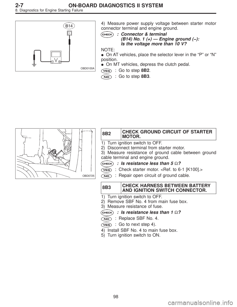
OBD0100A
4) Measure power supply voltage between starter motor
connector terminal and engine ground.
: Connector & terminal
(B14) No. 1 (+)—Engine ground (�):
Is the voltage more than 10 V?
NOTE:
�On AT vehicles, place the selector lever in the“P”or“N”
position.
�On MT vehicles, depress the clutch pedal.
: Go to step8B2.
: Go to step8B3.
OBD0725
8B2CHECK GROUND CIRCUIT OF STARTER
MOTOR.
1) Turn ignition switch to OFF.
2) Disconnect terminal from starter motor.
3) Measure resistance of ground cable between ground
cable terminal and engine ground.
: Is resistance less than 5Ω?
: Check starter motor.
: Repair open circuit of ground cable.
8B3CHECK HARNESS BETWEEN BATTERY
AND IGNITION SWITCH CONNECTOR.
1) Turn ignition switch to OFF.
2) Remove SBF No. 4 from main fuse box.
3) Measure resistance of fuse.
: Is resistance less than 1Ω?
: Replace SBF No. 4.
: Go to next step 4).
4) Install SBF No. 4 to main fuse box.
5) Turn ignition switch to ON.
98
2-7ON-BOARD DIAGNOSTICS II SYSTEM
8. Diagnostics for Engine Starting Failure
Page 2248 of 3342
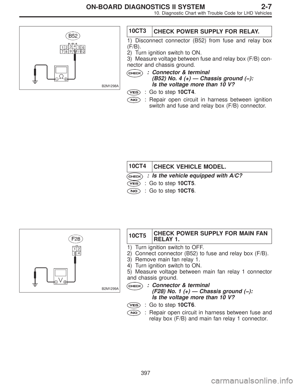
B2M1298A
10CT3
CHECK POWER SUPPLY FOR RELAY.
1) Disconnect connector (B52) from fuse and relay box
(F/B).
2) Turn ignition switch to ON.
3) Measure voltage between fuse and relay box (F/B) con-
nector and chassis ground.
: Connector & terminal
(B52) No. 4 (+)—Chassis ground (�):
Is the voltage more than 10 V?
: Go to step10CT4.
: Repair open circuit in harness between ignition
switch and fuse and relay box (F/B) connector.
10CT4
CHECK VEHICLE MODEL.
: Is the vehicle equipped with A/C?
: Go to step10CT5.
: Go to step10CT6.
B2M1299A
10CT5CHECK POWER SUPPLY FOR MAIN FAN
RELAY 1.
1) Turn ignition switch to OFF.
2) Connect connector (B52) to fuse and relay box (F/B).
3) Remove main fan relay 1.
4) Turn ignition switch to ON.
5) Measure voltage between main fan relay 1 connector
and chassis ground.
: Connector & terminal
(F28) No. 1 (+)—Chassis ground (�):
Is the voltage more than 10 V?
: Go to step10CT6.
: Repair open circuit in harness between fuse and
relay box (F/B) and main fan relay 1 connector.
397
2-7ON-BOARD DIAGNOSTICS II SYSTEM
10. Diagnostic Chart with Trouble Code for LHD Vehicles
Page 2250 of 3342
B2M0609A
10CT7CHECK OPEN CIRCUIT IN RADIATOR
FAN RELAY 1 CONTROL CIRCUIT.
1) Disconnect connector (F40) from fuse and relay box
(F/B).
2) Measure resistance of harness between ECM and main
fan relay 1 connector.
NOTE:
With A/C models only.
: Connector & terminal
(B84) No. 74—(F28) No. 3:
Is the resistance less than 1Ω?
: Go to next.
: Repair harness and connector.
NOTE:
In this case, repair the following:
�Open circuit in harness between ECM and main fan
relay 1 connector
�Poor contact in coupling connector (F45)
: Is there poor contact in ECM or main fan
relay 1 connector?
: Repair poor contact in ECM or main fan relay 1
connector.
: Go to next step 3).
399
2-7ON-BOARD DIAGNOSTICS II SYSTEM
10. Diagnostic Chart with Trouble Code for LHD Vehicles
Page 2414 of 3342
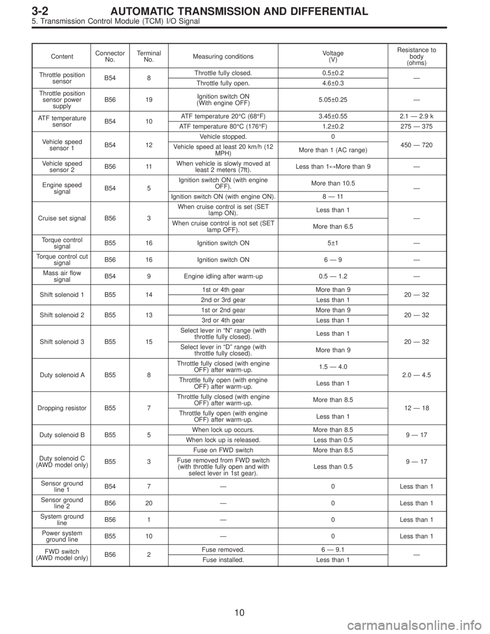
ContentConnector
No.Terminal
No.Measuring conditionsVoltage
(V)Resistance to
body
(ohms)
Throttle position
sensorB54 8Throttle fully closed. 0.5±0.2
—
Throttle fully open. 4.6±0.3
Throttle position
sensor power
supplyB56 19Ignition switch ON
(With engine OFF)5.05±0.25—
ATF temperature
sensorB54 10ATF temperature 20°C(68°F) 3.45±0.55 2.1—2.9 k
ATF temperature 80°C (176°F) 1.2±0.2 275—375
Vehicle speed
sensor 1B54 12Vehicle stopped. 0
450—720
Vehicle speed at least 20 km/h (12
MPH)More than 1 (AC range)
Vehicle speed
sensor 2B56 11When vehicle is slowly moved at
least 2 meters (7ft).Less than 1)More than 9—
Engine speed
signalB54 5Ignition switch ON (with engine
OFF).More than 10.5
—
Ignition switch ON (with engine ON). 8—11
Cruise set signal B56 3When cruise control is set (SET
lamp ON).Less than 1
—
When cruise control is not set (SET
lamp OFF).More than 6.5
Torque control
signalB55 16 Ignition switch ON 5±1—
Torque control cut
signalB56 16 Ignition switch ON 6—9—
Mass air flow
signalB54 9 Engine idling after warm-up 0.5—1.2—
Shift solenoid 1 B55 141st or 4th gear More than 9
20—32
2nd or 3rd gear Less than 1
Shift solenoid 2 B55 131st or 2nd gear More than 9
20—32
3rd or 4th gear Less than 1
Shift solenoid 3 B55 15Select lever in“N”range (with
throttle fully closed).Less than 1
20—32
Select lever in“D”range (with
throttle fully closed).More than 9
Duty solenoid A B55 8Throttle fully closed (with engine
OFF) after warm-up.1.5—4.0
2.0—4.5
Throttle fully open (with engine
OFF) after warm-up.Less than 1
Dropping resistor B55 7Throttle fully closed (with engine
OFF) after warm-up.More than 8.5
12—18
Throttle fully open (with engine
OFF) after warm-up.Less than 1
Duty solenoid B B55 5When lock up occurs. More than 8.5
9—17
When lock up is released. Less than 0.5
Duty solenoid C
(AWD model only)B55 3Fuse on FWD switch More than 8.5
9—17 Fuse removed from FWD switch
(with throttle fully open and with
select lever in 1st gear).Less than 0.5
Sensor ground
line 1B54 7—0 Less than 1
Sensor ground
line 2B56 20—0 Less than 1
System ground
lineB56 1—0 Less than 1
Power system
ground lineB55 10—0 Less than 1
FWD switch
(AWD model only)B56 2Fuse removed. 6—9.1
—
Fuse installed. Less than 1
10
3-2AUTOMATIC TRANSMISSION AND DIFFERENTIAL
5. Transmission Control Module (TCM) I/O Signal