Page 780 of 3342
G3M0424
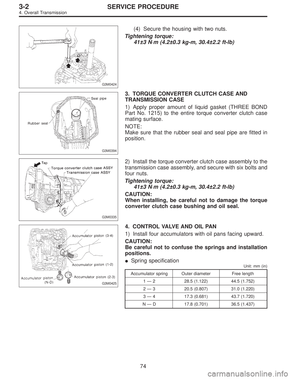
(4) Secure the housing with two nuts.
Tightening torque:
41±3 N⋅m (4.2±0.3 kg-m, 30.4±2.2 ft-lb)
G3M0394
3. TORQUE CONVERTER CLUTCH CASE AND
TRANSMISSION CASE
1) Apply proper amount of liquid gasket (THREE BOND
Part No. 1215) to the entire torque converter clutch case
mating surface.
NOTE:
Make sure that the rubber seal and seal pipe are fitted in
position.
G3M0335
2) Install the torque converter clutch case assembly to the
transmission case assembly, and secure with six bolts and
four nuts.
Tightening torque:
41±3 N⋅m (4.2±0.3 kg-m, 30.4±2.2 ft-lb)
CAUTION:
When installing, be careful not to damage the torque
converter clutch case bushing and oil seal.
G3M0425
4. CONTROL VALVE AND OIL PAN
1) Install four accumulators with oil pans facing upward.
CAUTION:
Be careful not to confuse the springs and installation
positions.
�Spring specification
Unit: mm (in)
Accumulator spring Outer diameter Free length
1—2 28.5 (1.122) 44.5 (1.752)
2—3 20.5 (0.807) 31.0 (1.220)
3—4 17.3 (0.681) 43.7 (1.720)
N—D 17.8 (0.701) 36.5 (1.437)
74
3-2SERVICE PROCEDURE
4. Overall Transmission
Page 812 of 3342
B3M0407A
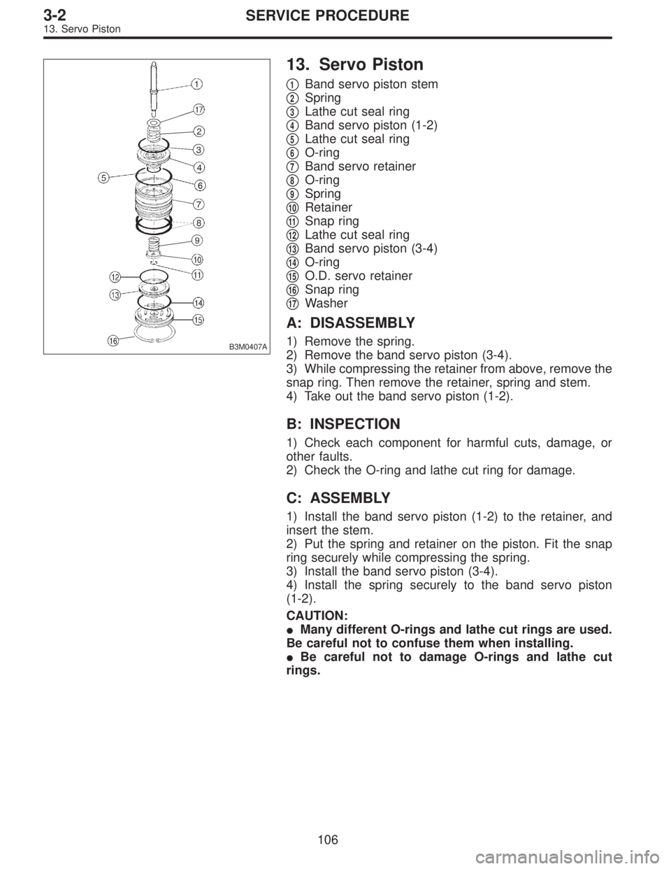
13. Servo Piston
�1Band servo piston stem
�
2Spring
�
3Lathe cut seal ring
�
4Band servo piston (1-2)
�
5Lathe cut seal ring
�
6O-ring
�
7Band servo retainer
�
8O-ring
�
9Spring
�
10Retainer
�
11Snap ring
�
12Lathe cut seal ring
�
13Band servo piston (3-4)
�
14O-ring
�
15O.D. servo retainer
�
16Snap ring
�
17Washer
A: DISASSEMBLY
1) Remove the spring.
2) Remove the band servo piston (3-4).
3) While compressing the retainer from above, remove the
snap ring. Then remove the retainer, spring and stem.
4) Take out the band servo piston (1-2).
B: INSPECTION
1) Check each component for harmful cuts, damage, or
other faults.
2) Check the O-ring and lathe cut ring for damage.
C: ASSEMBLY
1) Install the band servo piston (1-2) to the retainer, and
insert the stem.
2) Put the spring and retainer on the piston. Fit the snap
ring securely while compressing the spring.
3) Install the band servo piston (3-4).
4) Install the spring securely to the band servo piston
(1-2).
CAUTION:
�Many different O-rings and lathe cut rings are used.
Be careful not to confuse them when installing.
�Be careful not to damage O-rings and lathe cut
rings.
106
3-2SERVICE PROCEDURE
13. Servo Piston
Page 849 of 3342
G3M0870
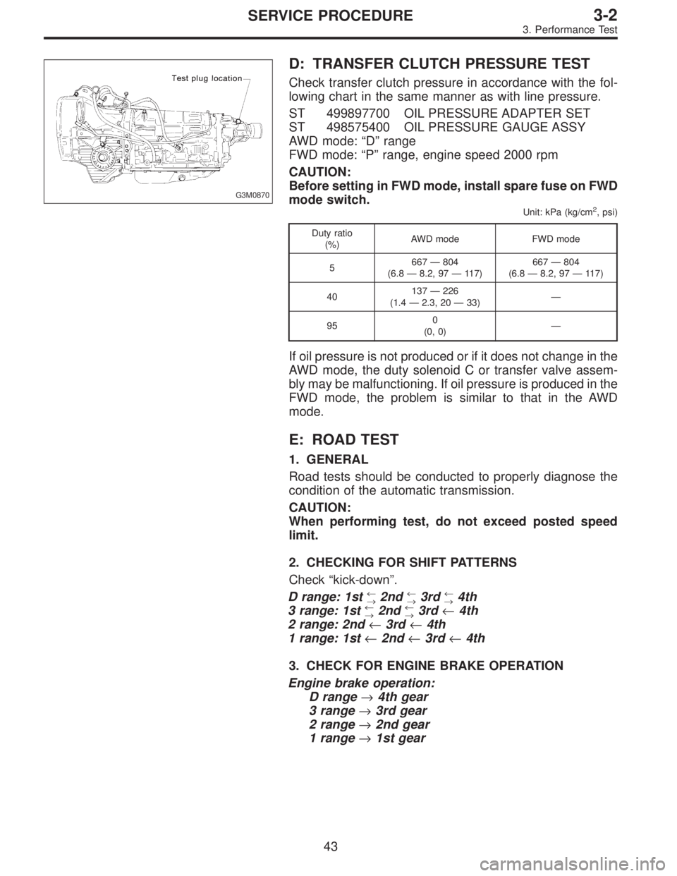
D: TRANSFER CLUTCH PRESSURE TEST
Check transfer clutch pressure in accordance with the fol-
lowing chart in the same manner as with line pressure.
ST 499897700 OIL PRESSURE ADAPTER SET
ST 498575400 OIL PRESSURE GAUGE ASSY
AWD mode:“D”range
FWD mode:“P”range, engine speed 2000 rpm
CAUTION:
Before setting in FWD mode, install spare fuse on FWD
mode switch.
Unit: kPa (kg/cm2, psi)
Duty ratio
(%)AWD mode FWD mode
5667—804
(6.8—8.2, 97—117)667—804
(6.8—8.2, 97—117)
40137—226
(1.4—2.3, 20—33)—
950
(0, 0)—
If oil pressure is not produced or if it does not change in the
AWD mode, the duty solenoid C or transfer valve assem-
bly may be malfunctioning. If oil pressure is produced in the
FWD mode, the problem is similar to that in the AWD
mode.
E: ROAD TEST
1. GENERAL
Road tests should be conducted to properly diagnose the
condition of the automatic transmission.
CAUTION:
When performing test, do not exceed posted speed
limit.
2. CHECKING FOR SHIFT PATTERNS
Check“kick-down”.
D range: 1st
←
→2nd←
→3rd←
→4th
3 range: 1st←
→2nd←
→3rd←4th
2 range: 2nd←3rd←4th
1 range: 1st←2nd←3rd←4th
3. CHECK FOR ENGINE BRAKE OPERATION
Engine brake operation:
D range→4th gear
3 range→3rd gear
2 range→2nd gear
1 range→1st gear
43
3-2SERVICE PROCEDURE
3. Performance Test
Page 866 of 3342
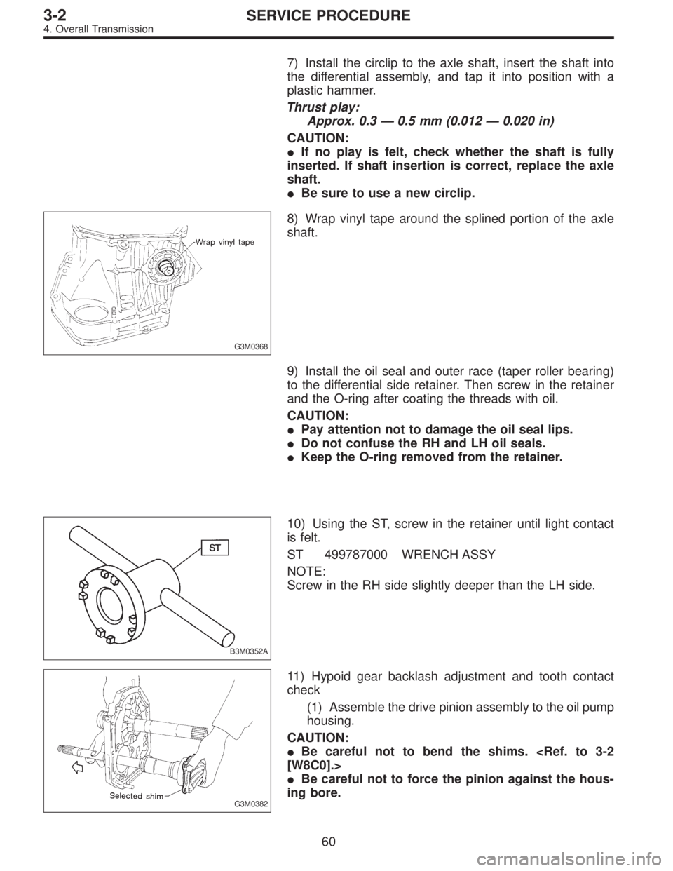
7) Install the circlip to the axle shaft, insert the shaft into
the differential assembly, and tap it into position with a
plastic hammer.
Thrust play:
Approx. 0.3—0.5 mm (0.012—0.020 in)
CAUTION:
�If no play is felt, check whether the shaft is fully
inserted. If shaft insertion is correct, replace the axle
shaft.
�Be sure to use a new circlip.
G3M0368
8) Wrap vinyl tape around the splined portion of the axle
shaft.
9) Install the oil seal and outer race (taper roller bearing)
to the differential side retainer. Then screw in the retainer
and the O-ring after coating the threads with oil.
CAUTION:
�Pay attention not to damage the oil seal lips.
�Do not confuse the RH and LH oil seals.
�Keep the O-ring removed from the retainer.
B3M0352A
10) Using the ST, screw in the retainer until light contact
is felt.
ST 499787000 WRENCH ASSY
NOTE:
Screw in the RH side slightly deeper than the LH side.
G3M0382
11) Hypoid gear backlash adjustment and tooth contact
check
(1) Assemble the drive pinion assembly to the oil pump
housing.
CAUTION:
�Be careful not to bend the shims.
[W8C0].>
�Be careful not to force the pinion against the hous-
ing bore.
60
3-2SERVICE PROCEDURE
4. Overall Transmission
Page 880 of 3342
G3M0424
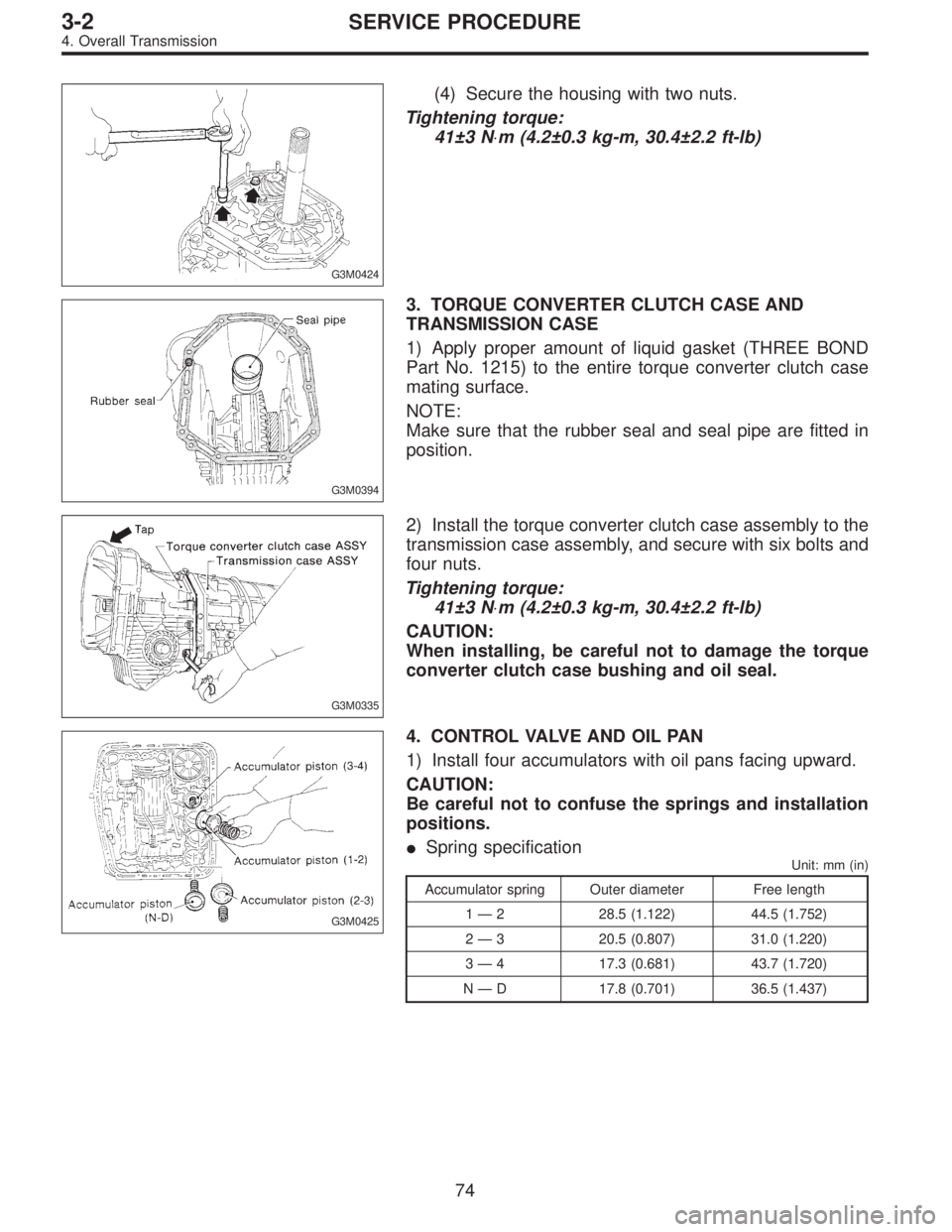
(4) Secure the housing with two nuts.
Tightening torque:
41±3 N⋅m (4.2±0.3 kg-m, 30.4±2.2 ft-lb)
G3M0394
3. TORQUE CONVERTER CLUTCH CASE AND
TRANSMISSION CASE
1) Apply proper amount of liquid gasket (THREE BOND
Part No. 1215) to the entire torque converter clutch case
mating surface.
NOTE:
Make sure that the rubber seal and seal pipe are fitted in
position.
G3M0335
2) Install the torque converter clutch case assembly to the
transmission case assembly, and secure with six bolts and
four nuts.
Tightening torque:
41±3 N⋅m (4.2±0.3 kg-m, 30.4±2.2 ft-lb)
CAUTION:
When installing, be careful not to damage the torque
converter clutch case bushing and oil seal.
G3M0425
4. CONTROL VALVE AND OIL PAN
1) Install four accumulators with oil pans facing upward.
CAUTION:
Be careful not to confuse the springs and installation
positions.
�Spring specification
Unit: mm (in)
Accumulator spring Outer diameter Free length
1—2 28.5 (1.122) 44.5 (1.752)
2—3 20.5 (0.807) 31.0 (1.220)
3—4 17.3 (0.681) 43.7 (1.720)
N—D 17.8 (0.701) 36.5 (1.437)
74
3-2SERVICE PROCEDURE
4. Overall Transmission
Page 912 of 3342
B3M0407A
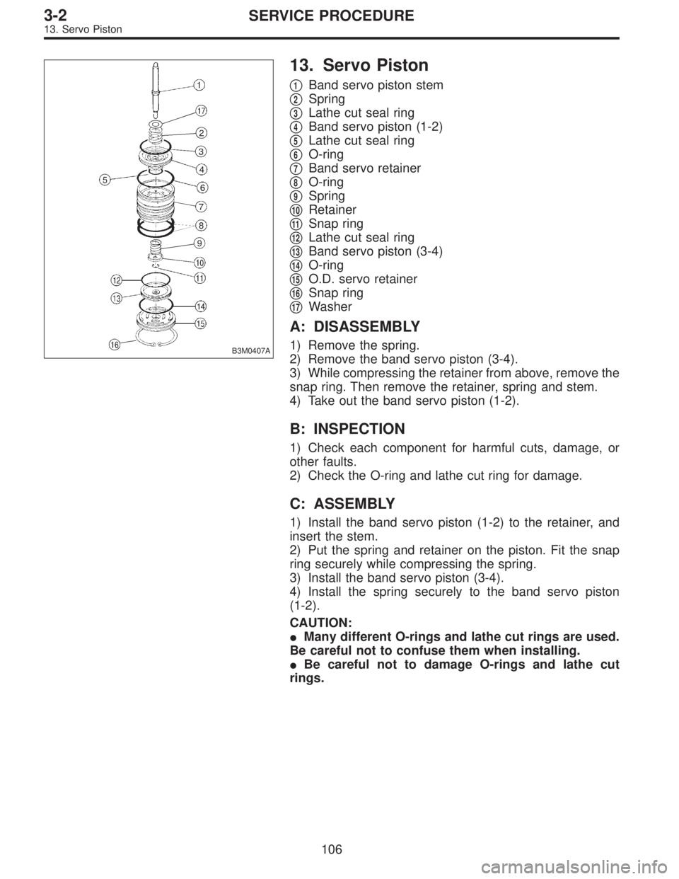
13. Servo Piston
�1Band servo piston stem
�
2Spring
�
3Lathe cut seal ring
�
4Band servo piston (1-2)
�
5Lathe cut seal ring
�
6O-ring
�
7Band servo retainer
�
8O-ring
�
9Spring
�
10Retainer
�
11Snap ring
�
12Lathe cut seal ring
�
13Band servo piston (3-4)
�
14O-ring
�
15O.D. servo retainer
�
16Snap ring
�
17Washer
A: DISASSEMBLY
1) Remove the spring.
2) Remove the band servo piston (3-4).
3) While compressing the retainer from above, remove the
snap ring. Then remove the retainer, spring and stem.
4) Take out the band servo piston (1-2).
B: INSPECTION
1) Check each component for harmful cuts, damage, or
other faults.
2) Check the O-ring and lathe cut ring for damage.
C: ASSEMBLY
1) Install the band servo piston (1-2) to the retainer, and
insert the stem.
2) Put the spring and retainer on the piston. Fit the snap
ring securely while compressing the spring.
3) Install the band servo piston (3-4).
4) Install the spring securely to the band servo piston
(1-2).
CAUTION:
�Many different O-rings and lathe cut rings are used.
Be careful not to confuse them when installing.
�Be careful not to damage O-rings and lathe cut
rings.
106
3-2SERVICE PROCEDURE
13. Servo Piston
Page 949 of 3342
G3M0870
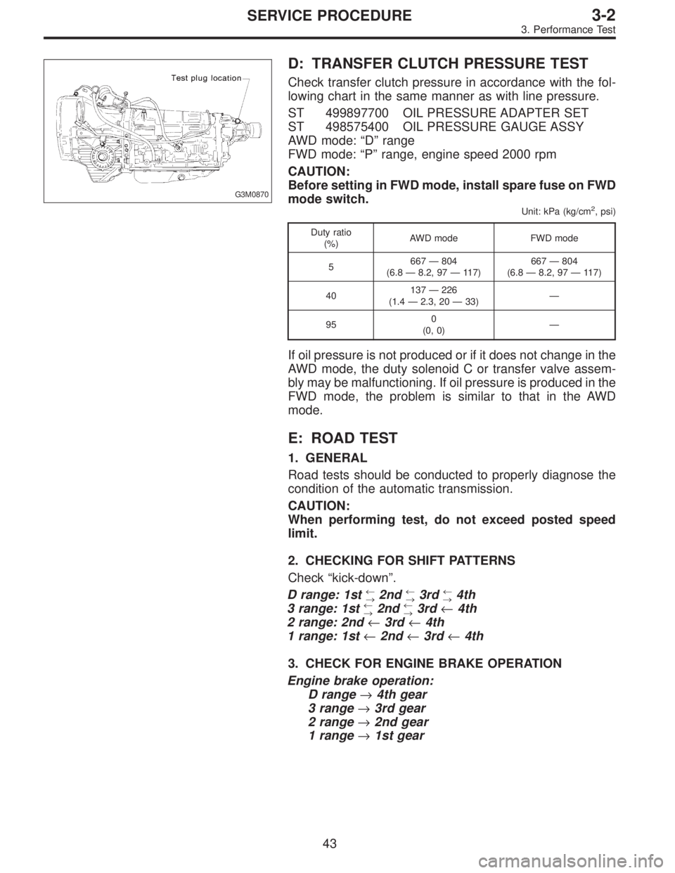
D: TRANSFER CLUTCH PRESSURE TEST
Check transfer clutch pressure in accordance with the fol-
lowing chart in the same manner as with line pressure.
ST 499897700 OIL PRESSURE ADAPTER SET
ST 498575400 OIL PRESSURE GAUGE ASSY
AWD mode:“D”range
FWD mode:“P”range, engine speed 2000 rpm
CAUTION:
Before setting in FWD mode, install spare fuse on FWD
mode switch.
Unit: kPa (kg/cm2, psi)
Duty ratio
(%)AWD mode FWD mode
5667—804
(6.8—8.2, 97—117)667—804
(6.8—8.2, 97—117)
40137—226
(1.4—2.3, 20—33)—
950
(0, 0)—
If oil pressure is not produced or if it does not change in the
AWD mode, the duty solenoid C or transfer valve assem-
bly may be malfunctioning. If oil pressure is produced in the
FWD mode, the problem is similar to that in the AWD
mode.
E: ROAD TEST
1. GENERAL
Road tests should be conducted to properly diagnose the
condition of the automatic transmission.
CAUTION:
When performing test, do not exceed posted speed
limit.
2. CHECKING FOR SHIFT PATTERNS
Check“kick-down”.
D range: 1st
←
→2nd←
→3rd←
→4th
3 range: 1st←
→2nd←
→3rd←4th
2 range: 2nd←3rd←4th
1 range: 1st←2nd←3rd←4th
3. CHECK FOR ENGINE BRAKE OPERATION
Engine brake operation:
D range→4th gear
3 range→3rd gear
2 range→2nd gear
1 range→1st gear
43
3-2SERVICE PROCEDURE
3. Performance Test
Page 966 of 3342
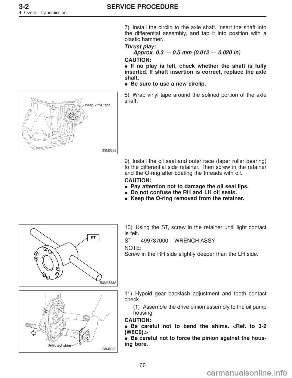
7) Install the circlip to the axle shaft, insert the shaft into
the differential assembly, and tap it into position with a
plastic hammer.
Thrust play:
Approx. 0.3—0.5 mm (0.012—0.020 in)
CAUTION:
�If no play is felt, check whether the shaft is fully
inserted. If shaft insertion is correct, replace the axle
shaft.
�Be sure to use a new circlip.
G3M0368
8) Wrap vinyl tape around the splined portion of the axle
shaft.
9) Install the oil seal and outer race (taper roller bearing)
to the differential side retainer. Then screw in the retainer
and the O-ring after coating the threads with oil.
CAUTION:
�Pay attention not to damage the oil seal lips.
�Do not confuse the RH and LH oil seals.
�Keep the O-ring removed from the retainer.
B3M0352A
10) Using the ST, screw in the retainer until light contact
is felt.
ST 499787000 WRENCH ASSY
NOTE:
Screw in the RH side slightly deeper than the LH side.
G3M0382
11) Hypoid gear backlash adjustment and tooth contact
check
(1) Assemble the drive pinion assembly to the oil pump
housing.
CAUTION:
�Be careful not to bend the shims.
[W8C0].>
�Be careful not to force the pinion against the hous-
ing bore.
60
3-2SERVICE PROCEDURE
4. Overall Transmission