Page 316 of 3342
1) Remove service hole cover and service hole plugs
using hexagon wrench (14 mm).
G2M0165
2) Rotate crankshaft to bring #1 and #2 pistons to bottom
dead center position, then remove piston circlip through
service hole of #1 and #2 cylinders.
G2M0166
3) Draw out piston pin from #1 and #2 pistons by using ST.
ST 499097500 PISTON PIN REMOVER
CAUTION:
Be careful not to confuse original combination of
piston, piston pin and cylinder.
4) Similarly remove piston pins from #3 and #4 pistons by
using ST.
5) Remove bolts which connect cylinder block on the side
of #2 and #4 cylinders.
6) Back off bolts which connect cylinder block on the side
of #1 and #3 cylinders two or three turns.
53
2-3SERVICE PROCEDURE
7. Cylinder Block
Page 317 of 3342
G2M0167
2. CYLINDER BLOCK
1) Set up cylinder block so that #1 and #3 cylinders are on
the upper side, then remove cylinder block connecting
bolts.
2) Separate left-hand and right-hand cylinder blocks.
CAUTION:
When separating cylinder block, do not allow the con-
necting rod to fall and damage the cylinder block.
3) Remove rear oil seal.
4) Remove crankshaft together with connecting rod.
5) Remove crankshaft bearings from cylinder block using
hammer handle.
CAUTION:
Do not confuse combination of crankshaft bearings.
Press bearing at the end opposite to locking lip.
6) Draw out each piston from cylinder block using wooden
bar or hammer handle.
CAUTION:
Do not confuse combination of piston and cylinder.
54
2-3SERVICE PROCEDURE
7. Cylinder Block
Page 396 of 3342
G2M0166
3) Draw out piston pin from #1 and #2 pistons by using ST.
ST 499097700 PISTON PIN REMOVER
CAUTION:
Be careful not to confuse original combination of
piston, piston pin and cylinder.
4) Similarly remove piston pins from #3 and #4 pistons by
using ST.
5) Remove bolts which connect cylinder block on the side
of #2 and #4 cylinders.
6) Back off bolts which connect cylinder block on the side
of #1 and #3 cylinders two or three turns.
55
2-3bSERVICE PROCEDURE
5. Cylinder Block
Page 397 of 3342
G2M0167
2. CYLINDER BLOCK
1) Set up cylinder block so that #1 and #3 cylinders are on
the upper side, then remove cylinder block connecting
bolts.
2) Separate left-hand and right-hand cylinder blocks.
CAUTION:
When separating cylinder block, do not allow the con-
necting rod to fall and damage the cylinder block.
3) Remove rear oil seal.
4) Remove crankshaft together with connecting rod.
5) Remove crankshaft bearings from cylinder block using
hammer handle.
CAUTION:
Do not confuse combination of crankshaft bearings.
Press bearing at the end opposite to locking lip.
6) Draw out each piston from cylinder block using wooden
bar or hammer handle.
CAUTION:
Do not confuse combination of piston and cylinder.
56
2-3bSERVICE PROCEDURE
5. Cylinder Block
Page 462 of 3342

CONDITION:
�Engine coolant temperature is above 95°C (203°F).
TROUBLE SYMPTOM:
�Radiator main fan does not operate under the above
condition.
1. Check fuse and power")
A: OPERATION (WITHOUT A/C MODEL)
CONDITION:
�Engine coolant temperature is above 95°C (203°F).
TROUBLE SYMPTOM:
�Radiator main fan does not operate under the above
condition.
1. Check fuse and power supply.
OK
�Not OK
Melted fuse,repair the shorted part of the circuit
,replace fuse.
2. Check harness connector between fuse and
relay box, and A/C relay holder.
OK
�Not OK
Repair or replace wiring harness.
3. Check A/C relay holder.
OK
�Not OK
Repair or replace A/C relay holder.
4. Check harness connector between A/C relay
holder and main fan motor.
OK
�Not OK
Repair or replace wiring harness.
5. Check ground circuit of main fan motor.
OK
�Not OK
Repair or replace wiring harness.
6. Check main fan motor.
OK
�Not OK
Replace main fan motor.
Refer to 2-7 On-Board Diagnostics II System.
B2M0427A
1. CHECK FUSE AND POWER SUPPLY.
1) Check fuse No. 13.
2) Turn ignition switch to ACC.
3) Measure voltage between fuse and relay box, and body.
Connector & terminal / Specified voltage:
(F40) No. 3—Body / 10 V, or more
�
�
�
�
�
�
22
2-5DIAGNOSTICS
2. Radiator Main Fan
Page 463 of 3342
 Turn ignition switch to OFF.
2) Disconnect connectors from fuse and relay box, and
A/C relay holder.
3) Measure")
B2M0325A
2. CHECK HARNESS CONNECTOR BETWEEN FUSE
AND RELAY BOX, AND A/C RELAY HOLDER.
1) Turn ignition switch to OFF.
2) Disconnect connectors from fuse and relay box, and
A/C relay holder.
3) Measure resistance of harness connector between fuse
and relay box, and A/C relay holder.
Connector & terminal / Specified resistance:
(F40) No. 3—(F29) No. 2 / 10Ω, max.
B2M0428A
3. CHECK A/C RELAY HOLDER.
1) Disconnect connector from A/C relay holder.
2) Measure resistance between terminals of A/C relay
holder.
Connector & terminal / Specified resistance:
(F29) No. 2—(F28) No. 4 / 10Ω, max.
(F29) No. 2—(F30) No. 4 / 10Ω, max.
B2M0366A
4. CHECK HARNESS CONNECTOR BETWEEN A/C
RELAY HOLDER AND MAIN FAN MOTOR.
1) Disconnect connectors from A/C relay holder and main
fan motor.
2) Measure resistance of harness connector between A/C
relay holder and main fan motor.
Connector & terminal / Specified resistance:
(F28) No. 4—(F17) No. 2 / 10Ω, max.
(F30) No. 4—(F17) No. 3 / 10Ω, max.
B2M0367A
5. CHECK GROUND CIRCUIT OF MAIN FAN MOTOR.
Measure resistance between main fan motor connector
and body.
Connector & terminal / Specified resistance:
(F17) No. 1—Body / 10Ω, max.
B2M0368A
6. CHECK MAIN FAN MOTOR.
1) Disconnect connector from main fan motor.
2) Connect battery positive (+) terminal to terminals No. 2
and No. 3, and connect terminal No. 1 to ground. Ensure
that fan rotates.
23
2-5DIAGNOSTICS
2. Radiator Main Fan
Page 464 of 3342
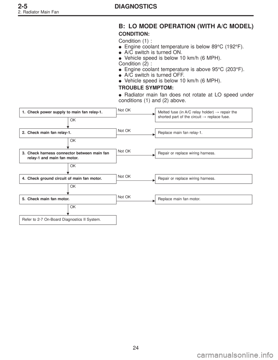
B: LO MODE OPERATION (WITH A/C MODEL)
CONDITION:
Condition (1) :
�Engine coolant temperature is below 89°C (192°F).
�A/C switch is turned ON.
�Vehicle speed is below 10 km/h (6 MPH).
Condition (2) :
�Engine coolant temperature is above 95°C (203°F).
�A/C switch is turned OFF.
�Vehicle speed is below 10 km/h (6 MPH).
TROUBLE SYMPTOM:
�Radiator main fan does not rotate at LO speed under
conditions (1) and (2) above.
1. Check power supply to main fan relay-1.
OK
�Not OK
Melted fuse (in A/C relay holder),repair the
shorted part of the circuit,replace fuse.
2. Check main fan relay-1.
OK
�Not OK
Replace main fan relay-1.
3. Check harness connector between main fan
relay-1 and main fan motor.
OK
�Not OK
Repair or replace wiring harness.
4. Check ground circuit of main fan motor.
OK
�Not OK
Repair or replace wiring harness.
5. Check main fan motor.
OK
�Not OK
Replace main fan motor.
Refer to 2-7 On-Board Diagnostics II System.
�
�
�
�
�
24
2-5DIAGNOSTICS
2. Radiator Main Fan
Page 467 of 3342

CONDITION:
Condition (1) :
�Engine coolant temperature is below 89°C (192°F).
�A/C switch is turned ON.
�Vehicle speed is over 20 km/h (12 MPH).
Condition (2) :")
C: HI MODE OPERATION (WITH A/C MODEL)
CONDITION:
Condition (1) :
�Engine coolant temperature is below 89°C (192°F).
�A/C switch is turned ON.
�Vehicle speed is over 20 km/h (12 MPH).
Condition (2) :
�Engine coolant temperature is above 95°C (203°F).
�A/C switch is turned OFF.
�Vehicle speed is over 20 km/h (12 MPH).
Condition (3) :
�Engine coolant temperature is above 95°C (203°F).
�A/C switch is turned ON.
TROUBLE SYMPTOM:
�Radiator main fan does not rotate at HI speed under
conditions (1), (2) and (3) above.
1. Check operation of main fan motor LO mode.
OK
�Not OK
Check LO mode operation.
2. Check power supply to main fan relay-2.
OK
�Not OK
Melted fuse (in A/C relay holder),repair the
shorted part of the circuit,replace fuse.
3. Check main fan relay-2.
OK
�Not OK
Replace main fan relay-2.
4. Check harness connector between main fan
relay-2 and main fan motor.
OK
�Not OK
Repair or replace wiring harness.
5. Check ground circuit of main fan motor.
OK
�Not OK
Repair or replace wiring harness.
6. Check main fan motor.
OK
�Not OK
Replace main fan motor.
Refer to 2-7 On-Board Diagnostics II System.
�
�
�
�
�
�
27
2-5DIAGNOSTICS
2. Radiator Main Fan
 Remove service hole cover and service hole plugs
using hexagon wrench (14 mm).
G2M0165
2) Rotate crankshaft to bring #1 and #2 pistons to bottom
dead center position, then remove piston circlip thr")
 Set up cylinder block so that #1 and #3 cylinders are on
the upper side, then remove cylinder block connecting
bolts.
2) Separate left-hand and right-hand cylinder blocks.")
 Draw out piston pin from #1 and #2 pistons by using ST.
ST 499097700 PISTON PIN REMOVER
CAUTION:
Be careful not to confuse original combination of
piston, piston pin and cylinder.
4) Simila")
 Set up cylinder block so that #1 and #3 cylinders are on
the upper side, then remove cylinder block connecting
bolts.
2) Separate left-hand and right-hand cylinder blocks.")