Page 1364 of 3342
 In the case of AWD AT vehicles, install a spare fuse with
the FWD connector in the engine compartment to simulate
FWD vehicles")
G4M0462
2. CHECKING THE HYDRAULIC UNIT ABS
OPERATION WITH BRAKE TESTER
1) In the case of AWD AT vehicles, install a spare fuse with
the FWD connector in the engine compartment to simulate
FWD vehicles.
2) Prepare for operationing ABS sequence control.
to 4-4 [W15D1] or 4-4 [W15D2].>
G4M0464
3) Set the front wheels or rear wheels on the brake tester
and set the select lever’s position at“neutral”.
4) Operate the brake tester.
5) Perform ABS sequence control.
step 1 or 4-4 [W15D2] step 1.>
6) Hydraulic unit begins to work; and check the following
working sequence.
(1) The FL wheel performs decompression, holding,
and compression in sequence, and subsequently the
FR wheel repeats the cycle.
(2) The RR wheel performs decompression, holding,
and compression in sequence, and subsequently the
RL wheel repeats the cycle.
7) Read values indicated on the brake tester and check if
the fluctuation of values, when decompressed and
compressed, meet the standard values.
Unit: N (kg, lb)
Initial value When decompressed When compressed
Front wheel 981 (100, 221) 490 (50, 110) or less 981 (100, 221) or more
Rear wheel 981 (100, 221) 490 (50, 110) or less 981 (100, 221) or more
8) After checking, also check if any irregular brake pedal
tightness is felt.
82
4-4SERVICE PROCEDURE
15. Hydraulic Unit for ABS System (ABS 5.3 Type)
Page 1410 of 3342
 In the case of AWD AT vehicles, install a spare fuse with
the FWD connector in the engine compartment to simulate
FWD vehicles")
G4M0462
2. CHECKING THE HYDRAULIC UNIT ABS
OPERATION WITH BRAKE TESTER
1) In the case of AWD AT vehicles, install a spare fuse with
the FWD connector in the engine compartment to simulate
FWD vehicles.
2) Prepare for operating ABS sequence control.
4-4 [W22D1] or 4-4 [W22D2].>
G4M0464
3) Set the front wheels or rear wheels on the brake tester
and set the select lever’s position at“neutral”.
4) Operate the brake tester.
5) Perform ABS sequence control.
step 1 or 4-4 [W22D2] step 1.>
6) Hydraulic unit begins to work; and check the following
working sequence.
(1) The FL wheel performs decompression, holding,
and compression in sequence, and subsequently the
FR wheel repeats the cycle.
(2) The RR wheel performs decompression, holding,
and compression in sequence, and subsequently the
RL wheel repeats the cycle.
7) Read values indicated on the brake tester and check if
the fluctuation of values, when decompressed and
compressed, meet the standard values.
Unit: N (kg, lb)
Initial value When decompressed When compressed
Front wheel 981 (100, 221) 490 (50, 110) or less 981 (100, 221) or more
Rear wheel 981 (100, 221) 490 (50, 110) or less 981 (100, 221) or more
8) After checking, also check if any irregular brake pedal
tightness is felt.
125
4-4SERVICE PROCEDURE
22. ABS Control Module and Hydraulic Control Unit (ABSCM&H/U) (ABS 5.3i Type)
Page 1456 of 3342
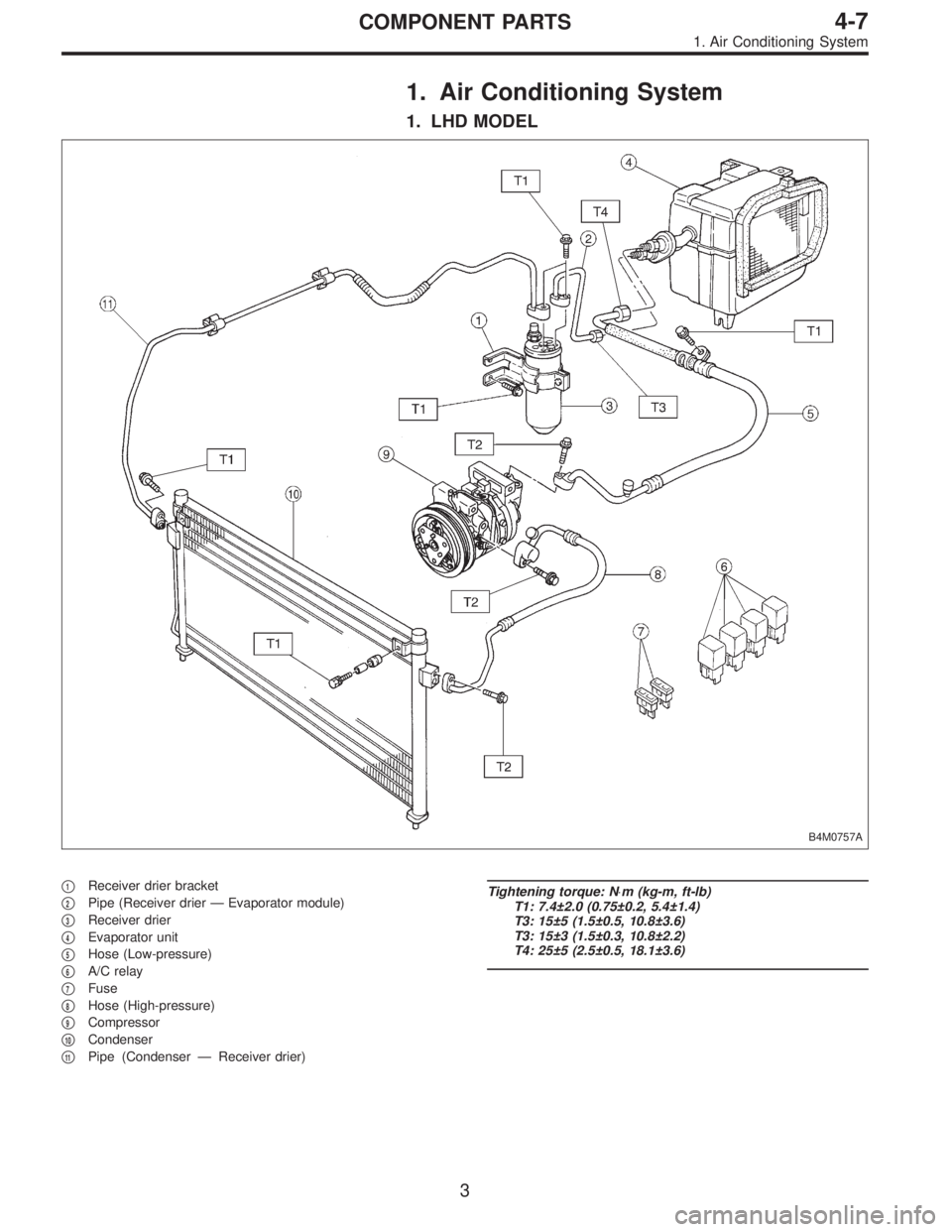
1. Air Conditioning System
1. LHD MODEL
B4M0757A
�1Receiver drier bracket
�
2Pipe (Receiver drier—Evaporator module)
�
3Receiver drier
�
4Evaporator unit
�
5Hose (Low-pressure)
�
6A/C relay
�
7Fuse
�
8Hose (High-pressure)
�
9Compressor
�
10Condenser
�
11Pipe (Condenser—Receiver drier)
Tightening torque: N⋅m (kg-m, ft-lb)
T1: 7.4±2.0 (0.75±0.2, 5.4±1.4)
T3: 15±5 (1.5±0.5, 10.8±3.6)
T3: 15±3 (1.5±0.3, 10.8±2.2)
T4: 25±5 (2.5±0.5, 18.1±3.6)
3
4-7COMPONENT PARTS
1. Air Conditioning System
Page 1457 of 3342
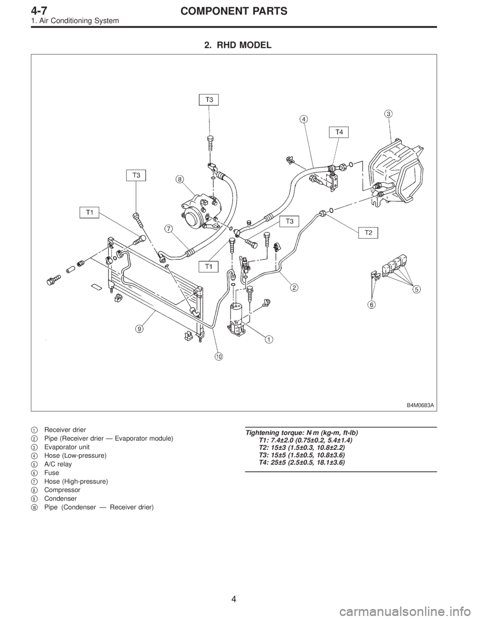
2. RHD MODEL
B4M0683A
�1Receiver drier
�
2Pipe (Receiver drier—Evaporator module)
�
3Evaporator unit
�
4Hose (Low-pressure)
�
5A/C relay
�
6Fuse
�
7Hose (High-pressure)
�
8Compressor
�
9Condenser
�
10Pipe (Condenser—Receiver drier)
Tightening torque: N⋅m (kg-m, ft-lb)
T1: 7.4±2.0 (0.75±0.2, 5.4±1.4)
T2: 15±3 (1.5±0.3, 10.8±2.2)
T3: 15±5 (1.5±0.5, 10.8±3.6)
T4: 25±5 (2.5±0.5, 18.1±3.6)
4
4-7COMPONENT PARTS
1. Air Conditioning System
Page 1496 of 3342
G4M0649
17. Relay and Fuse
A: LOCATION
Relays used with A/C system are located as shown in fig-
ure.
1) A/C relay
2) Main fan (radiator fan) relay
3) Sub fan (condenser fan) relay
4) Sub fan (condenser fan) water temperature relay
5) Fuses (10 A and 20 A)
G4M0651
B: INSPECTION
1) Check conduction with a circuit tester (ohm range)
according to the following table in figure.
B4M0105A
2) Replace relays which do not meet specifications.
39
4-7SERVICE PROCEDURE
17. Relay and Fuse
Page 1583 of 3342

1. Sunroof
Entry of water into compartment�
1Check roof panel and glass lid assembly for improper or poor
sealing.
�
2Check drain tube for clogging.
�
3Check sunroof frame seal and body for improper fit.
Booming noise�
1Check glass lid assembly and roof panel for improper clear-
ance.
�
2Check sun shade and roof trim for improper clearance.
Abnormal motor noise�
1Check motor for looseness.
�
2Check gears and bearings for wear.
�
3Check cable for wear.
�
4Check cable pipe for deformities.
Failure of sunroof to operate
(Motor operates properly.)�
1Check guide rail for foreign particles.
�
2Check guide rail for improper installation.
�
3Check parts for mutual interference.
�
4Check cable slider for improper clinching.
�
5Check cable for improper installation.
�
6Check clutch adjustment nut for improper tightness.
Motor does not rotate or rotates improperly.
(Use sunroof wrench to check operation.)�
1Check fuse for blowout.
�
2Check switch for improper function.
�
3Check motor for incorrect terminal voltage.
�
4Check relay for improper operation.
�
5Check poor grounding system.
�
6Check cords for discontinuity and terminals for poor connec-
tions.
�
7Check limit switch for improper operation.
62
5-1DIAGNOSTICS
1. Sunroof
Page 1640 of 3342
B5M0042
6) Remove lap anchor cover and then remove lower
anchor bolt.
7) Remove outer belt assembly.
8) Installation is in the reverse order of removal. Ensure
that seat belt is properly reeled on and off after installation
of ELR.
CAUTION:
�Be extremely careful not to confuse center seat
anchor plate with outer seat anchor plate during instal-
lation.
�Ensure that seat belts are free from twisting after
installation.
�Ensure that tongues, buckles and belts are properly
placed on seat.
B5M0046A
5. Inner Trim Panel
A: REMOVAL AND INSTALLATION
1. SIDE SILL COVER
1) Remove front pillar lower trim�
1.
2) Remove side sill rear upper cover trim�
2.
B5M0047
2. CENTER PILLAR LOWER
Remove center pillar lower trim.
13
5-3SERVICE PROCEDURE
4. Rear Seat Belt - 5. Inner Trim Panel
Page 1641 of 3342
B5M0042
6) Remove lap anchor cover and then remove lower
anchor bolt.
7) Remove outer belt assembly.
8) Installation is in the reverse order of removal. Ensure
that seat belt is properly reeled on and off after installation
of ELR.
CAUTION:
�Be extremely careful not to confuse center seat
anchor plate with outer seat anchor plate during instal-
lation.
�Ensure that seat belts are free from twisting after
installation.
�Ensure that tongues, buckles and belts are properly
placed on seat.
B5M0046A
5. Inner Trim Panel
A: REMOVAL AND INSTALLATION
1. SIDE SILL COVER
1) Remove front pillar lower trim�
1.
2) Remove side sill rear upper cover trim�
2.
B5M0047
2. CENTER PILLAR LOWER
Remove center pillar lower trim.
13
5-3SERVICE PROCEDURE
4. Rear Seat Belt - 5. Inner Trim Panel
 A/C relay
2) Main fan (radiator fan) relay
3) Sub fan (condenser fan) relay
4) Sub fan (condense")
 Remove lap anchor cover and then remove lower
anchor bolt.
7) Remove outer belt assembly.
8) Installation is in the reverse order of removal. Ensure
that seat belt is properly reeled on and")
 Remove lap anchor cover and then remove lower
anchor bolt.
7) Remove outer belt assembly.
8) Installation is in the reverse order of removal. Ensure
that seat belt is properly reeled on and")