Page 1781 of 3342
 Burned or shorted contacts
2) Broken or weak spring
3) Damaged harness
4) Worn or corroded mating surface of")
B: INSPECTION
1. HORN SWITCH
Ensure that horn switch is free from the following defects:
1) Burned or shorted contacts
2) Broken or weak spring
3) Damaged harness
4) Worn or corroded mating surface of horn plate
B6M0126A
2. HORN RELAY
Check continuity between terminals as indicated in table
below, when connecting the battery to terminals No. 1 and
No. 2.
When current flows. Between terminals
No. 2 and No. 3Continuity exists.
When current does not flow. Between terminals
No. 2 and No. 3Continuity does not
exist.
Between terminals
No. 1 and No. 2Continuity exists.
B6M0127
3. HORN
Make sure that horn sounds when battery voltage is
applied between connector terminal and horn body.
4. CIGARETTE LIGHTER
1) Remove plug. Then, check element’s contact for wear,
and element for accumulation of ashes, foreign particles,
etc.
2) Check element for discontinuity.
3) Remove socket and clean element. Then, check for
wear or foreign particles on element’s contact and mating
surface.
4) Ensure that cigarette lighter returns within 20 seconds
after it is turned to ON.
16. Power Window
A: REMOVAL AND INSTALLATION
1. MAIN SWITCH, SUB SWITCH AND POWER
WINDOW MOTOR
Refer to 5-2 [W2A2] as for removal and installation of
power window main switch, sub switch and motor.
NOTE:
To remove the power window motor, it is necessary to dis-
assemble the door component parts.
38
6-2SERVICE PROCEDURE
15. Horn and Cigarette Lighter - 16. Power Window
Page 1782 of 3342
B6M0128A
B: INSPECTION
1. MAIN SWITCH
Set power window main switch to each position and check
continuity between terminals as indicated in table below:
LHD model
Window lock switchSwitch
PositionFront RH Front LH Rear RH Rear LH
7 14 9 12 7 13 8 12 7 6 11 12 7 10 5 12
NORMALUP��
��������������
OFF������������
DOWN��������
��������
LOCKUP��
��������
OFF���������
DOWN����������
RHD model
Window lock switchSwitch
PositionFront RH Front LH Rear RH Rear LH
7 11 6 12 7 10 5 12 7 9 14 12 7 13 8 12
AUTO UP��
��
UP����������������
OFF������������
DOWN��������
��������
AUTO DOWN����
39
6-2SERVICE PROCEDURE
15. Horn and Cigarette Lighter - 16. Power Window
Page 1783 of 3342
B6M0129A
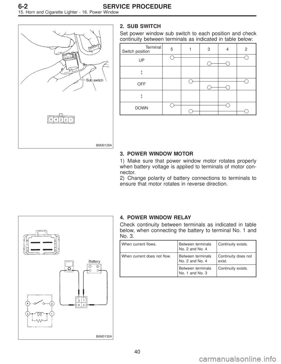
2. SUB SWITCH
Set power window sub switch to each position and check
continuity between terminals as indicated in table below:
Terminal
Switch position51342
UP��
��
*
OFF��
��
*
DOWN��
��
3. POWER WINDOW MOTOR
1) Make sure that power window motor rotates properly
when battery voltage is applied to terminals of motor con-
nector.
2) Change polarity of battery connections to terminals to
ensure that motor rotates in reverse direction.
B6M0130A
4. POWER WINDOW RELAY
Check continuity between terminals as indicated in table
below, when connecting the battery to terminal No. 1 and
No. 3.
When current flows. Between terminals
No. 2 and No. 4Continuity exists.
When current does not flow. Between terminals
No. 2 and No. 4Continuity does not
exist.
Between terminals
No. 1 and No. 3Continuity exists.
40
6-2SERVICE PROCEDURE
15. Horn and Cigarette Lighter - 16. Power Window
Page 1784 of 3342
17. Power Door Lock
A: REMOVAL AND INSTALLATION
1. FRONT AND REAR DOOR, AND REAR GATE LOCK
ACTUATOR
Refer to 5-2 [W2A7] as for removal and installation of front
door lock actuator, rear door lock actuators, and rear gate
lock actuator.
NOTE:
To remove and install the actuators, it is necessary to dis-
assemble the door component parts.
G6M0095
2. DOOR LOCK TIMER
1) Disconnect battery ground cable.
B3M0377A
2) Remove lower cover and then disconnect connector.
B6M0683A
3) Remove door lock timer�1while disconnecting connec-
tor.
4) Installation is in the reverse order of removal.
Tightening torque:
T: 7.4±2.5 N⋅m (0.75±0.25 kg-m, 5.4±1.8 ft-lb)
41
6-2SERVICE PROCEDURE
17. Power Door Lock
Page 1785 of 3342
![SUBARU LEGACY 1997 Service Repair Manual B6M0762
B: INSPECTION
1. DOOR LOCK SWITCH (DRIVER’S AND FRONT
PASSENGER’S DOOR)
1) Remove door trim panel. <Ref. to 5-2 [W2A2].>
2) Set switch to each position and check continuity
between termina](/manual-img/17/57434/w960_57434-1784.png "SUBARU LEGACY 1997 Service Repair Manual B6M0762
B: INSPECTION
1. DOOR LOCK SWITCH (DRIVER’S AND FRONT
PASSENGER’S DOOR)
1) Remove door trim panel. <Ref. to 5-2 [W2A2].>
2) Set switch to each position and check continuity
between termina")
B6M0762
B: INSPECTION
1. DOOR LOCK SWITCH (DRIVER’S AND FRONT
PASSENGER’S DOOR)
1) Remove door trim panel.
2) Set switch to each position and check continuity
between terminals as indicated in table below:
Terminal
Switch position542
UNLOCK��
LOCK��
B6M0135
2. ACTUATOR
1) Remove door trim panel.
2) Disconnect connector of actuator.
3) Make sure that door link moves to LOCK or UNLOCK
position when battery voltage is applied between terminals
as described below:
�Connect battery positive (+) terminal to terminal No. 2,
and negative (�) terminal to terminal No. 4 at a moment.
�Connect battery positive (+) terminal to terminal No. 4,
and negative terminal (�) to terminal No. 2 at a moment.
B6M0352A
18. Remote Controlled Rearview Mirror
A: REMOVAL AND INSTALLATION
1. REMOTE CONTROLLED REARVIEW MIRROR
SWITCH
1) Remove rearview mirror switch from instrument panel
by using a small standard screwdriver.
CAUTION:
Do not pry rearview mirror switch forcefully as this
may scratch instrument panel.
2) Remove rearview mirror switch while disconnecting
connector.
42
6-2SERVICE PROCEDURE
17. Power Door Lock - 18. Remote Controlled Rearview Mirror
Page 1786 of 3342
![SUBARU LEGACY 1997 Service Repair Manual B6M0762
B: INSPECTION
1. DOOR LOCK SWITCH (DRIVER’S AND FRONT
PASSENGER’S DOOR)
1) Remove door trim panel. <Ref. to 5-2 [W2A2].>
2) Set switch to each position and check continuity
between termina](/manual-img/17/57434/w960_57434-1785.png "SUBARU LEGACY 1997 Service Repair Manual B6M0762
B: INSPECTION
1. DOOR LOCK SWITCH (DRIVER’S AND FRONT
PASSENGER’S DOOR)
1) Remove door trim panel. <Ref. to 5-2 [W2A2].>
2) Set switch to each position and check continuity
between termina")
B6M0762
B: INSPECTION
1. DOOR LOCK SWITCH (DRIVER’S AND FRONT
PASSENGER’S DOOR)
1) Remove door trim panel.
2) Set switch to each position and check continuity
between terminals as indicated in table below:
Terminal
Switch position542
UNLOCK��
LOCK��
B6M0135
2. ACTUATOR
1) Remove door trim panel.
2) Disconnect connector of actuator.
3) Make sure that door link moves to LOCK or UNLOCK
position when battery voltage is applied between terminals
as described below:
�Connect battery positive (+) terminal to terminal No. 2,
and negative (�) terminal to terminal No. 4 at a moment.
�Connect battery positive (+) terminal to terminal No. 4,
and negative terminal (�) to terminal No. 2 at a moment.
B6M0352A
18. Remote Controlled Rearview Mirror
A: REMOVAL AND INSTALLATION
1. REMOTE CONTROLLED REARVIEW MIRROR
SWITCH
1) Remove rearview mirror switch from instrument panel
by using a small standard screwdriver.
CAUTION:
Do not pry rearview mirror switch forcefully as this
may scratch instrument panel.
2) Remove rearview mirror switch while disconnecting
connector.
42
6-2SERVICE PROCEDURE
17. Power Door Lock - 18. Remote Controlled Rearview Mirror
Page 1787 of 3342
![SUBARU LEGACY 1997 Service Repair Manual B6M0137
2. REARVIEW MIRROR
1) Remove door trim panel. <Ref. to 5-2 [W2A2].>
2) Disconnect connector of rearview mirror.
3) Remove screws which secure rearview mirror, and then
remove rearview mirror.](/manual-img/17/57434/w960_57434-1786.png "SUBARU LEGACY 1997 Service Repair Manual B6M0137
2. REARVIEW MIRROR
1) Remove door trim panel. <Ref. to 5-2 [W2A2].>
2) Disconnect connector of rearview mirror.
3) Remove screws which secure rearview mirror, and then
remove rearview mirror.")
B6M0137
2. REARVIEW MIRROR
1) Remove door trim panel.
2) Disconnect connector of rearview mirror.
3) Remove screws which secure rearview mirror, and then
remove rearview mirror.
B6M0826A
3. MIRROR PLATE
1) Remove rearview mirror.
2) Warm around the mirror holder by hair dryer.
CAUTION:
The mirror holder will become extremely hot. Avoid
carelessly touching it.
B6M0827
3) Remove mirror plate while lifting the mirror holder using
a flat bladed screwdriver.
NOTE:
When removing mirror plate in vehicles with mirror heater,
disconnect mirror connector which is on the back side.
4) Installation is in the reverse order of removal.
B6M0139A
B: INSPECTION
1. REARVIEW MIRROR SWITCH
Move rearview mirror switch to each position and check
continuity between terminals as indicated in table below:
Switch
position
TerminalMirror switch Left/Right changing switch
OFF Right Left Up Down Left N Right
7�
9�
6�
8�
2����
����
1�
���
��� �
4����
3
43
6-2SERVICE PROCEDURE
18. Remote Controlled Rearview Mirror
Page 1788 of 3342
B6M0140
2. REARVIEW MIRROR
Check to ensure that rearview mirror moves properly when
battery voltage is applied to terminals as indicated in table
below:
OperationTerminal connection
(+) (�)
UP 3 1
DOWN 1 3
RIGHT 1 2
LEFT 2 1
44
6-2SERVICE PROCEDURE
18. Remote Controlled Rearview Mirror

![SUBARU LEGACY 1997 Service Repair Manual 17. Power Door Lock
A: REMOVAL AND INSTALLATION
1. FRONT AND REAR DOOR, AND REAR GATE LOCK
ACTUATOR
Refer to 5-2 [W2A7] as for removal and installation of front
door lock actuator, rear door lock actu](/manual-img/17/57434/w960_57434-1783.png "SUBARU LEGACY 1997 Service Repair Manual 17. Power Door Lock
A: REMOVAL AND INSTALLATION
1. FRONT AND REAR DOOR, AND REAR GATE LOCK
ACTUATOR
Refer to 5-2 [W2A7] as for removal and installation of front
door lock actuator, rear door lock actu")
 (�)
UP 3 1
DOW")