Page 1789 of 3342
![SUBARU LEGACY 1997 Service Repair Manual 19. Sunroof
A: REMOVAL AND INSTALLATION
1. SUNROOF AND SUNROOF MOTOR
Refer to 5-1 [W16A0] as for removal and installation of
sunroof system.
B6M0353A
2. SUNROOF SWITCH
NOTE:
The sunroof switch is inst](/manual-img/17/57434/w960_57434-1788.png "SUBARU LEGACY 1997 Service Repair Manual 19. Sunroof
A: REMOVAL AND INSTALLATION
1. SUNROOF AND SUNROOF MOTOR
Refer to 5-1 [W16A0] as for removal and installation of
sunroof system.
B6M0353A
2. SUNROOF SWITCH
NOTE:
The sunroof switch is inst")
19. Sunroof
A: REMOVAL AND INSTALLATION
1. SUNROOF AND SUNROOF MOTOR
Refer to 5-1 [W16A0] as for removal and installation of
sunroof system.
B6M0353A
2. SUNROOF SWITCH
NOTE:
The sunroof switch is installed in spot light body.
1) Pry spot light lens off using a screwdriver.
2) Remove screws which secure spot light body.
3) Remove spot light body while disconnecting connec-
tors.
4) Remove screw which secures sunroof switch, and then
remove sunroof switch.
B6M0142A
B: INSPECTION
1. SUNROOF SWITCH
Set sunroof switch to each position and check continuity
between terminals as indicated in table below:
Terminal
Switch position43652
Open��
Close��
Tilt up��
Tilt down��
B6M0503
2. SUNROOF MOTOR
1) Apply battery voltage between 1-pin connector and
body ground wire.
2) Make sure that sunroof motor moves when connecting
terminals as described below:
�Connect between terminals No. 3 and 4 (OPEN)
�Connect between terminals No. 6 and 4 (CLOSE)
�Connect between terminals No. 5 and 4 (TILT UP)
�Connect between terminals No. 2 and 4 (TILT DOWN)
45
6-2SERVICE PROCEDURE
19. Sunroof
Page 1790 of 3342
B6M0144A
3. SUNROOF RELAY
Check continuity between terminals as indicated in table
below, when battery voltage is applied between terminals
No. 1 and No. 3.
When current flows. Between terminals
No. 2 and No. 4Continuity exists.
When current does not flow. Between terminals
No. 2 and No. 4Continuity does not
exist.
Between terminals
No. 1 and No. 3Continuity exists.
B6M0354
20. Radio, Speaker and Antenna
A: REMOVAL AND INSTALLATION
1. RADIO BODY
1) Remove hand brake cover.
2) Remove console cover.
3) Remove screws which secure center panel. Remove
center panel.
B6M0355
4) Remove fitting screws, and slightly pull radio out of
instrument panel.
5) Disconnect connectors and antenna feeder cord.
B6M0146
2. FRONT SPEAKER
1) Remove gusset speaker from behind the rearview mir-
ror while disconnecting connector.
2) Remove door trim panel.
46
6-2SERVICE PROCEDURE
19. Sunroof - 20. Radio, Speaker and Antenna
Page 1791 of 3342
B6M0144A
3. SUNROOF RELAY
Check continuity between terminals as indicated in table
below, when battery voltage is applied between terminals
No. 1 and No. 3.
When current flows. Between terminals
No. 2 and No. 4Continuity exists.
When current does not flow. Between terminals
No. 2 and No. 4Continuity does not
exist.
Between terminals
No. 1 and No. 3Continuity exists.
B6M0354
20. Radio, Speaker and Antenna
A: REMOVAL AND INSTALLATION
1. RADIO BODY
1) Remove hand brake cover.
2) Remove console cover.
3) Remove screws which secure center panel. Remove
center panel.
B6M0355
4) Remove fitting screws, and slightly pull radio out of
instrument panel.
5) Disconnect connectors and antenna feeder cord.
B6M0146
2. FRONT SPEAKER
1) Remove gusset speaker from behind the rearview mir-
ror while disconnecting connector.
2) Remove door trim panel.
46
6-2SERVICE PROCEDURE
19. Sunroof - 20. Radio, Speaker and Antenna
Page 1792 of 3342
 Disconnect connector from speaker.
4) Remove screws which secure the speaker.
5) Remove door mount speaker.
3. REAR SPEAKER (SEDAN)
1) Remove rear seat cushion and rear backrest.
2) Remove")
B6M0162
3) Disconnect connector from speaker.
4) Remove screws which secure the speaker.
5) Remove door mount speaker.
3. REAR SPEAKER (SEDAN)
1) Remove rear seat cushion and rear backrest.
2) Remove left and right rear quarter trim panels.
3) Remove rear shelf trim panel.
4) Remove screws which secure speaker.
5) Remove speaker while disconnecting connector from
speaker.
4. REAR SPEAKER (WAGON)
1) Remove door trim panel.
2) Disconnect connector from speaker.
3) Remove screws which secure the speaker.
4) Remove speaker.
B6M0147A
5. POWER ANTENNA
1) Remove left side trunk trim (SEDAN), or left side rear
lower quarter trim (WAGON).
2) Remove special nut (SEDAN).
3) Remove bolt which secures power antenna.
4) Remove power antenna while disconnecting connector
and water drain hose.
B6M0149A
B: INSPECTION
1. POWER ANTENNA
1) Connect battery positive (+) terminal to terminal No. 3
and connect terminal No. 1 (SEDAN) or No. 6 (WAGON)
to ground. Ensure that antenna rod extends properly when
battery positive (+) terminal is connected to terminal No. 2
(SEDAN) or No. 4 (WAGON).
2) Ensure that antenna rod retracts properly when battery
positive (+) terminal is disconnected from terminal No. 2
(SEDAN) or No. 4 (WAGON).
47
6-2SERVICE PROCEDURE
20. Radio, Speaker and Antenna
Page 1793 of 3342
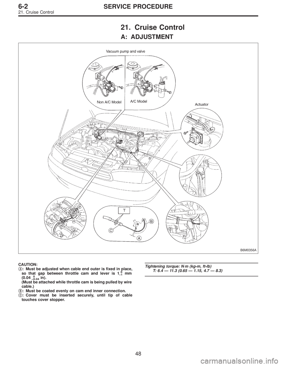
21. Cruise Control
A: ADJUSTMENT
B6M0356A
CAUTION:
�A: Must be adjusted when cable end outer is fixed in place,
so that gap between throttle cam and lever is 10
�1mm
(0.040
�0.04in).
(Must be attached while throttle cam is being pulled by wire
cable.)
�
B: Must be coated evenly on cam end inner connection.
�C: Cover must be inserted securely, until tip of cable
touches cover stopper.
Tightening torque: N⋅m (kg-m, ft-lb)
T: 6.4—11.3 (0.65—1.15, 4.7—8.3)
48
6-2SERVICE PROCEDURE
21. Cruise Control
Page 1794 of 3342
 Remove screws which secure meter visor.
2) Remove meter visor from instrument panel while dis-
connecting connectors.
3) Remove cr")
B6M0154A
B: REMOVAL AND INSTALLATION
1. CRUISE CONTROL MAIN SWITCH
1) Remove screws which secure meter visor.
2) Remove meter visor from instrument panel while dis-
connecting connectors.
3) Remove cruise control main switch from meter visor.
B6M0357A
2. CRUISE CONTROL COMMAND SWITCH
1) Remove screw which secures horn pad to the base of
steering wheel.
2) Remove horn pad from steering wheel while discon-
necting connector.
3) Disconnect connector of cruise control command
switch.
4) Remove screws which secure cruise control command
switch to steering wheel, and then remove command
switch.
WARNING:
Refer to 5-5 when removing or installing the module
from the airbag equipped model.
B6M0156
3. ACTUATOR
1) Loosen nut which secures cruise control cable end to
throttle cam, and then remove cable from engine throttle
cam.
2) Remove clip bands from cruise control cable.
CAUTION:
�Be careful not to apply excessive load to the wire
cable when adjusting and/or installing; otherwise, the
actuator may be deformed or damaged.
�Do not bend cable sharply with a radius less than
100 mm (3.94 in); otherwise, cable may bend
permanently, resulting in poor performance.
�When installing cable, be careful not to sharply bend
or pinch the inner cable; otherwise, the cable may
break.
49
6-2SERVICE PROCEDURE
21. Cruise Control
Page 1795 of 3342
B6M0358
3) Remove nuts which secure actuator.
4) Remove actuator while disconnecting vacuum hose.
Tightening torque:
7.4±1.5 N⋅m (0.75±0.15 kg-m, 5.4±1.1 ft-lb)
B6M0359A
4. VACUUM PUMP AND VALVES
1) Disconnect connector from vacuum pump.
2) Remove bolts which secure vacuum pump.
3) Remove A/C receiver/drier bracket.
4) Remove vacuum pump while disconnecting vacuum
hose.
Tightening torque:
7.4±1.5 N⋅m (0.75±0.15 kg-m, 5.4±1.1 ft-lb)
5. STOP AND BRAKE SWITCH
Refer to 4-5 [C101] (MT) or 4-5 [C201] (AT) as for removal
and installation of stop and brake switch.
6. CLUTCH SWITCH (MT)
Refer to 4-5 [C101] as for removal and installation of clutch
switch.
7. INHIBITOR SWITCH (AT)
Refer to 3-2 [W4A3] as for removal and installation of
inhibitor switch.
G6M0095
8. CRUISE CONTROL MODULE
1) Disconnect battery ground cable.
B3M0377A
2) Remove lower cover and then disconnect connector.
50
6-2SERVICE PROCEDURE
21. Cruise Control
Page 1796 of 3342
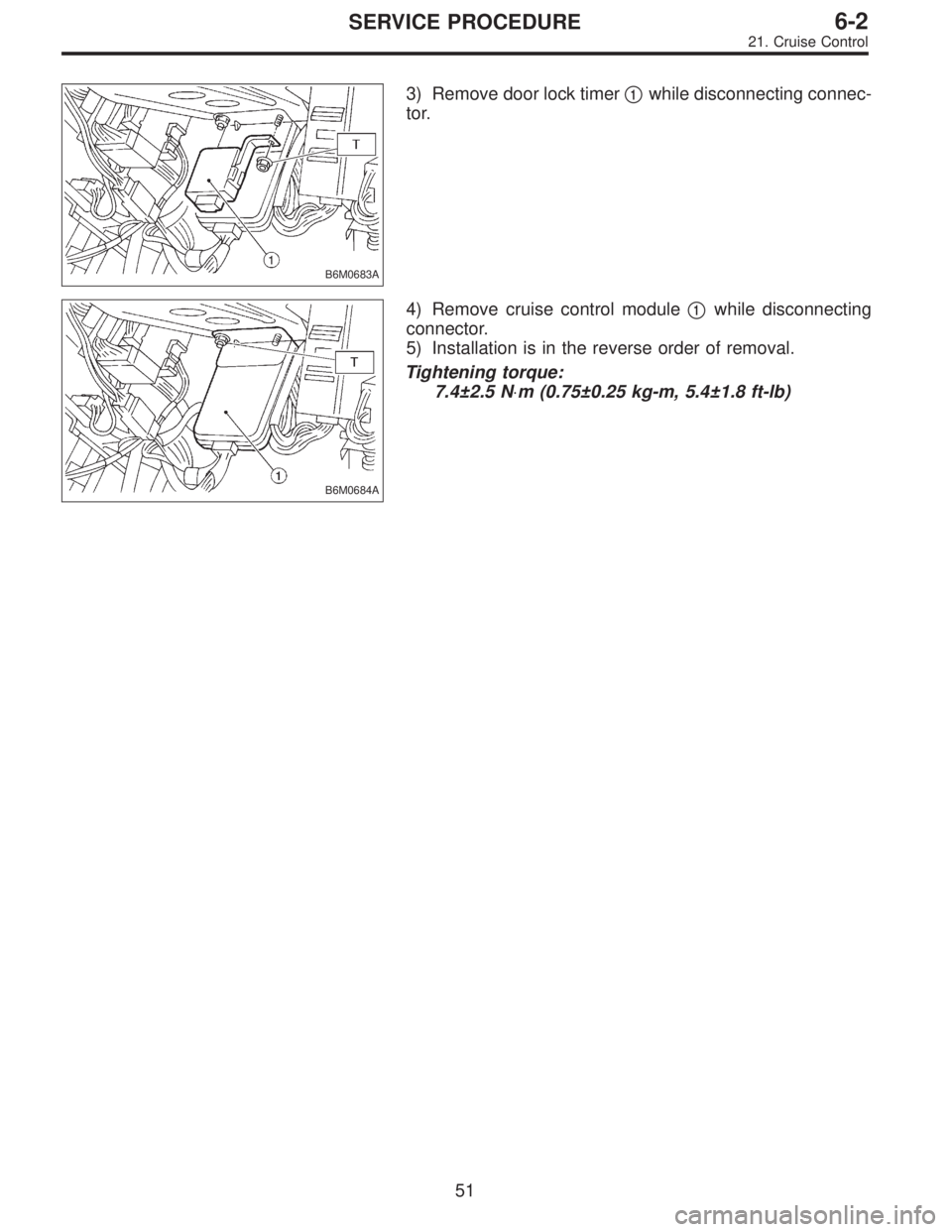
B6M0683A
3) Remove door lock timer�1while disconnecting connec-
tor.
B6M0684A
4) Remove cruise control module�1while disconnecting
connector.
5) Installation is in the reverse order of removal.
Tightening torque:
7.4±2.5 N⋅m (0.75±0.25 kg-m, 5.4±1.8 ft-lb)
51
6-2SERVICE PROCEDURE
21. Cruise Control


 Remove nuts which secure actuator.
4) Remove actuator while disconnecting vacuum hose.
Tightening torque:
7.4±1.5 N⋅m (0.75±0.15 kg-m, 5.4±1.1 ft-lb)
B6M0359A
4. VACUUM PUMP AND VALVES")