Page 1773 of 3342

B6M0119
B: INSPECTION
1. DEFOGGER SWITCH
Move rear window defogger switch to each position and
check continuity between terminals as indicated in table
below:
Terminal
Switch position35 14 2
OFF�
�
ON�����
G6M0112
2. DEFOGGER RELAY
Check continuity between terminals as indicated in table
below, when connecting the battery to terminal No. 1 and
No. 3.
When current flows.Between terminals
No. 2 and No. 4Continuity exists.
When current does not flow.Between terminals
No. 2 and No. 4Continuity does not
exist.
Between terminals
No. 1 and No. 3Continuity exists.
G6M0135
3. HEAT WIRES
1) Start the engine so that battery is being charged.
2) Turn defogger switch to ON.
3) Check each heat wire at its center position for discon-
tinuity by setting direct current voltmeter.
Normal indication is about 6 volts.
G6M0136
NOTE:
When measuring voltage, wind a piece of tin foil around the
tip of the tester probe and press the foil against the wire
with your finger.
32
6-2SERVICE PROCEDURE
12. Rear Window Defogger
Page 1774 of 3342
 When tester indicates 12 volts when its probe reaches
point“A”, a broken circuit occurs between point“A”and the
negative terminal. Slowly move tester probe toward the
negative termi")
G6M0137
4) When tester indicates 12 volts when its probe reaches
point“A”, a broken circuit occurs between point“A”and the
negative terminal. Slowly move tester probe toward the
negative terminal while contacting it on heat wire to locate
point where tester indication changes abruptly (0 volts).
This is the point where a broken circuit occurs.
When tester indicates 0 volts when its probe reaches point
“A”, a broken circuit occurs between point“A”and the posi-
tive terminal. Locate a point where tester indication
changes abruptly (12 volts) while slowly moving tester
probe toward the positive terminal.
G6M0138
C: REPAIR
1) Clean broken wire and its surrounding area.
2) Cut off slit on (used) thin film by 0.5 mm (0.020 in) width
and 10 mm (0.39 in) length.
3) Place the slit on glass along the broken wire, and
deposit conductive silver composition (DUPONT No. 4817)
on the broken portion.
4) Dry out the deposited portion.
5) Inspect the repaired wire for continuity.
B6M0120
13. Combination Meter
A: REMOVAL AND INSTALLATION
1. COMBINATION METER
1) Move steering wheel fully down.
2) Remove screws which secure meter visor.
3) Remove visor from instrument panel.
4) Disconnect connectors from meter visor.
B6M0121
5) Remove screws which secure combination meter, and
pull combination meter out.
6) Disconnect connectors from back of combination meter.
CAUTION:
When installing combination meter, be sure to connect
connectors to backside of combination meter.
33
6-2SERVICE PROCEDURE
12. Rear Window Defogger - 13. Combination Meter
Page 1775 of 3342
 When tester indicates 12 volts when its probe reaches
point“A”, a broken circuit occurs between point“A”and the
negative terminal. Slowly move tester probe toward the
negative termi")
G6M0137
4) When tester indicates 12 volts when its probe reaches
point“A”, a broken circuit occurs between point“A”and the
negative terminal. Slowly move tester probe toward the
negative terminal while contacting it on heat wire to locate
point where tester indication changes abruptly (0 volts).
This is the point where a broken circuit occurs.
When tester indicates 0 volts when its probe reaches point
“A”, a broken circuit occurs between point“A”and the posi-
tive terminal. Locate a point where tester indication
changes abruptly (12 volts) while slowly moving tester
probe toward the positive terminal.
G6M0138
C: REPAIR
1) Clean broken wire and its surrounding area.
2) Cut off slit on (used) thin film by 0.5 mm (0.020 in) width
and 10 mm (0.39 in) length.
3) Place the slit on glass along the broken wire, and
deposit conductive silver composition (DUPONT No. 4817)
on the broken portion.
4) Dry out the deposited portion.
5) Inspect the repaired wire for continuity.
B6M0120
13. Combination Meter
A: REMOVAL AND INSTALLATION
1. COMBINATION METER
1) Move steering wheel fully down.
2) Remove screws which secure meter visor.
3) Remove visor from instrument panel.
4) Disconnect connectors from meter visor.
B6M0121
5) Remove screws which secure combination meter, and
pull combination meter out.
6) Disconnect connectors from back of combination meter.
CAUTION:
When installing combination meter, be sure to connect
connectors to backside of combination meter.
33
6-2SERVICE PROCEDURE
12. Rear Window Defogger - 13. Combination Meter
Page 1776 of 3342
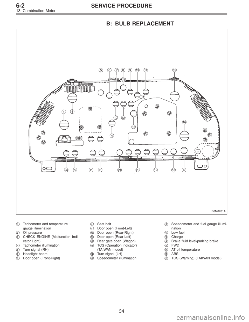
B: BULB REPLACEMENT
B6M0761A
�1Tachometer and temperature
gauge illumination
�
2Oil pressure
�
3CHECK ENGINE (Malfunction Indi-
cator Light)
�
4Tachometer illumination
�
5Turn signal (RH)
�
6Headlight beam
�
7Door open (Front-Right)�
8Seat belt
�
9Door open (Front-Left)
�
10Door open (Rear-Right)
�
11Door open (Rear-Left)
�
12Rear gate open (Wagon)
�
13TCS (Operation indicator)
(TAIWAN model)
�
14Turn signal (LH)
�
15Speedometer illumination�
16Speedometer and fuel gauge illumi-
nation
�
17Low fuel
�
18Charge
�
19Brake fluid level/parking brake
�
20FWD
�
21AT oil temperature
�
22ABS
�
23TCS (Warning) (TAIWAN model)
34
6-2SERVICE PROCEDURE
13. Combination Meter
Page 1777 of 3342
 Be careful not to drop or bump sensor as this may break
built-in magnet.
2) Drive key is designed to separate from vehicle speed
sensor 2. Be caref")
14. Vehicle Speed Sensor 2
A: GENERAL PRECAUTIONS
1) Be careful not to drop or bump sensor as this may break
built-in magnet.
2) Drive key is designed to separate from vehicle speed
sensor 2. Be careful not to lose it or forget to install.
3) Vehicle speed sensor 2 is installed in part (which con-
tains bearings, etc., finished to a high degree of accuracy).
Do not allow foreign matter (filings, sand, etc.) to get into
it.
4) When checking output of vehicle speed sensor 2 as a
single unit, ensure test leads are connected to their correct
terminals. Failure to do this may damage internal IC.
5) Discard vehicle speed sensor 2 after removal; replace
with new one.
B: REMOVAL
CAUTION:
�Be careful when removing vehicle speed sensor 2
immediately after driving vehicle for a while, as tem-
perature around it is high.
�Before removing vehicle speed sensor 2, clean dirt,
etc. from surrounding areas. Take care not to allow
foreign matter to get into mounting hole.
B2M0211
1) Remove collector cover.
2) Disconnect vehicle speed sensor 2 connector.
3) Turn and remove vehicle speed sensor 2.
4) Remove key and packing.
35
6-2SERVICE PROCEDURE
14. Vehicle Speed Sensor 2
Page 1778 of 3342
C: INSTALLATION
CAUTION:
�Ensure sensor mounting hole is clean and free of
foreign matter.
�Apply grease to tip end of key to prevent key from
falling off sensor.
�Align tip end of key with key groove on end of
speedometer shaft during installation.
1) Hand tighten vehicle speed sensor 2, then tighten it
using suitable tool.
Tightening torque required for sensor to reach bottom of
transmission is as follows:
Tightening torque:
0.39—0.88 N⋅m (4.0—9.0 kg-cm, 3.5—7.8 in-lb)
CAUTION:
�When torque must be applied that exceeds 0.88 N⋅m
(9.0 kg-cm, 7.8 in-lb), the key and key groove on end of
speedometer may not be aligned properly. Remove the
key, align it correctly and reassemble.
�Sensor threads are secured by Locktite. The reas-
sembly must be completed within 5 minutes before
Locktite dries.
2) Tighten vehicle speed sensor 2 further to specified
torque.
Tightening torque:
5.9±1.5 N⋅m (60±15 kg-cm, 52±13 in-lb)
36
6-2SERVICE PROCEDURE
14. Vehicle Speed Sensor 2
Page 1779 of 3342
 Open the engine hood.
2) Disconnect connector of horn.
3) Remove the horn.
Tightening torque:
18±5 N⋅m (1.8±0.5 kg-m,")
B6M0349
15. Horn and Cigarette Lighter
A: REMOVAL AND INSTALLATION
1. HORN
1) Open the engine hood.
2) Disconnect connector of horn.
3) Remove the horn.
Tightening torque:
18±5 N⋅m (1.8±0.5 kg-m, 13.0±3.6 ft-lb)
CAUTION:
After installing horn, connect connector, fit firmly wir-
ing harness to prevent from disconnecting due to
vibration.
B6M0124
2. HORN SWITCH (HORN PAD)
1) Remove screw which secures horn switch (steering
pad) to the base of steering wheel.
2) Remove horn switch (steering pad) from steering wheel
while disconnecting connector.
B6M0350A
3. CIGARETTE LIGHTER
1) Remove center panel from instrument panel.
5-4 [W1A0].>
2) Disconnect connector from cigarette lighter.
3) Turn illumination socket 45°counterclockwise and
remove it.
4) Loosen nut, and then remove cigarette lighter body.
CAUTION:
�Align socket with cutout portion of instrument panel
during installation.
�In case of replacing cigarette lighter, use genuine
part only and always replace both plug and socket
combination.
37
6-2SERVICE PROCEDURE
15. Horn and Cigarette Lighter
Page 1780 of 3342
 Burned or shorted contacts
2) Broken or weak spring
3) Damaged harness
4) Worn or corroded mating surface of")
B: INSPECTION
1. HORN SWITCH
Ensure that horn switch is free from the following defects:
1) Burned or shorted contacts
2) Broken or weak spring
3) Damaged harness
4) Worn or corroded mating surface of horn plate
B6M0126A
2. HORN RELAY
Check continuity between terminals as indicated in table
below, when connecting the battery to terminals No. 1 and
No. 2.
When current flows. Between terminals
No. 2 and No. 3Continuity exists.
When current does not flow. Between terminals
No. 2 and No. 3Continuity does not
exist.
Between terminals
No. 1 and No. 2Continuity exists.
B6M0127
3. HORN
Make sure that horn sounds when battery voltage is
applied between connector terminal and horn body.
4. CIGARETTE LIGHTER
1) Remove plug. Then, check element’s contact for wear,
and element for accumulation of ashes, foreign particles,
etc.
2) Check element for discontinuity.
3) Remove socket and clean element. Then, check for
wear or foreign particles on element’s contact and mating
surface.
4) Ensure that cigarette lighter returns within 20 seconds
after it is turned to ON.
16. Power Window
A: REMOVAL AND INSTALLATION
1. MAIN SWITCH, SUB SWITCH AND POWER
WINDOW MOTOR
Refer to 5-2 [W2A2] as for removal and installation of
power window main switch, sub switch and motor.
NOTE:
To remove the power window motor, it is necessary to dis-
assemble the door component parts.
38
6-2SERVICE PROCEDURE
15. Horn and Cigarette Lighter - 16. Power Window