Page 1729 of 3342
B6M0570A
6) Remove #3 spark plug cord by pulling boot, not cord
itself.
7) For subsequent procedures, refer to the procedure for
#1 spark plug.
G6M0095
4. #4 SPARK PLUG
1) Disconnect battery ground cable.
B6M0554
2) Remove battery.
B6M0561
3) Remove washer tank mounting bolts.
B6M0562A
4) Disconnect washer tank connectors.
CAUTION:
Do not disconnect washer tank hoses as washer fluid
will leak out from washer tank.
33
6-1SERVICE PROCEDURE
3. Spark Plug
Page 1730 of 3342
![SUBARU LEGACY 1997 Service Repair Manual B6M0575A
5) Move washer tank upward.
B6M0563A
6) Remove #4 spark plug cord by pulling boot, not cord
itself.
7) For subsequent procedures, refer to the procedure for
#1 spark plug. <Ref. to 6-1 [W3E1] SUBARU LEGACY 1997 Service Repair Manual B6M0575A
5) Move washer tank upward.
B6M0563A
6) Remove #4 spark plug cord by pulling boot, not cord
itself.
7) For subsequent procedures, refer to the procedure for
#1 spark plug. <Ref. to 6-1 [W3E1]](/manual-img/17/57434/w960_57434-1729.png)
B6M0575A
5) Move washer tank upward.
B6M0563A
6) Remove #4 spark plug cord by pulling boot, not cord
itself.
7) For subsequent procedures, refer to the procedure for
#1 spark plug.
CAUTION:
When removing spark plug, cover the ATF cooling
pipes with a rag to prevent damage.
B6M0572A
NOTE:
For easier removal of spark plug, diagonally insert the tools
from the direction of battery stand into plug hole as shown
in figure.
B6M0573
F: INSTALLATION (2500 cc OUTBACK
MODEL)
1. #1 SPARK PLUG
1) After setting spark plug in spark plug socket, connect
the spark plug socket, extension and Universal Joint to
each other.
2) Screw spark plug into cylinder head using the con-
nected tools above mentioned. At this point, it is necessary
to support the rear end of the tools with fingertips.
3) When spark plug is screwed in two or three turns, tem-
porarily disconnect the tools connected in step 1) above.
4) Confirm that spark plug is screwed into the cylinder
head properly by touching it with finger. If it is difficult to
reach it by hand, confirm its condition by using mirror and
suchlike.
5) Cover ABS pipes with rag to prevent damage.
34
6-1SERVICE PROCEDURE
3. Spark Plug
Page 1731 of 3342

B6M0574
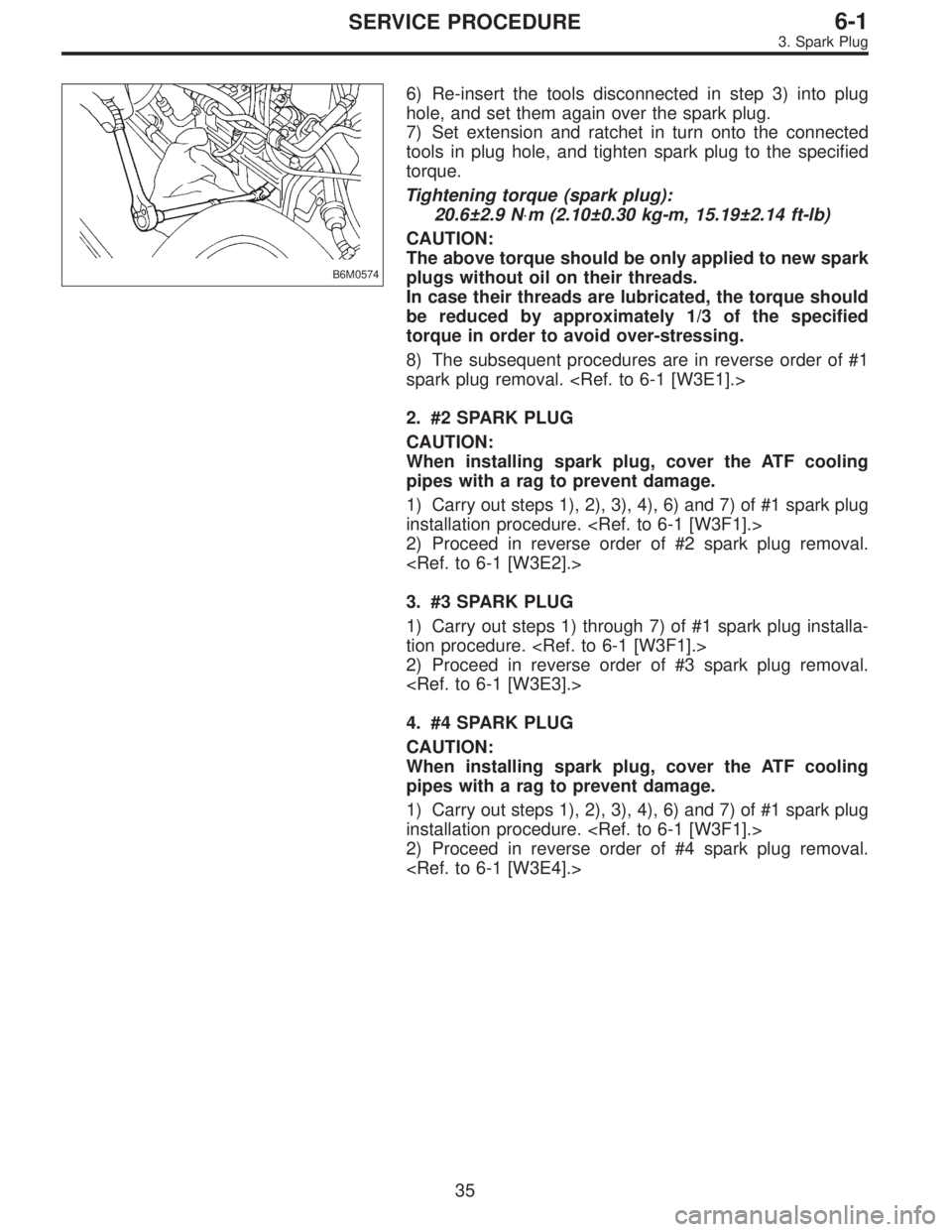
6) Re-insert the tools disconnected in step 3) into plug
hole, and set them again over the spark plug.
7) Set extension and ratchet in turn onto the connected
tools in plug hole, and tighten spark plug to the specified
torque.
Tightening torque (spark plug):
20.6±2.9 N⋅m (2.10±0.30 kg-m, 15.19±2.14 ft-lb)
CAUTION:
The above torque should be only applied to new spark
plugs without oil on their threads.
In case their threads are lubricated, the torque should
be reduced by approximately 1/3 of the specified
torque in order to avoid over-stressing.
8) The subsequent procedures are in reverse order of #1
spark plug removal.
2. #2 SPARK PLUG
CAUTION:
When installing spark plug, cover the ATF cooling
pipes with a rag to prevent damage.
1) Carry out steps 1), 2), 3), 4), 6) and 7) of #1 spark plug
installation procedure.
2) Proceed in reverse order of #2 spark plug removal.
3. #3 SPARK PLUG
1) Carry out steps 1) through 7) of #1 spark plug installa-
tion procedure.
2) Proceed in reverse order of #3 spark plug removal.
4. #4 SPARK PLUG
CAUTION:
When installing spark plug, cover the ATF cooling
pipes with a rag to prevent damage.
1) Carry out steps 1), 2), 3), 4), 6) and 7) of #1 spark plug
installation procedure.
2) Proceed in reverse order of #4 spark plug removal.
35
6-1SERVICE PROCEDURE
3. Spark Plug
Page 1732 of 3342

B6M0160
4. Ignition Coil
A: REMOVAL AND INSTALLATION
1. EXCEPT 2200 cc MODEL
1) Disconnect battery ground cable.
2) Disconnect connector from ignition coil.
3) Remove ignition coil.
4) Installation is in the reverse order of removal.
CAUTION:
Be sure to connect wires to their proper positions.
Failure to do so will damage unit.
B6M0772
2. 2200 cc MODEL
1) Disconnect battery ground cable.
2) Disconnect connector from ignition coil.
3) Disconnect spark plug cords from ignition coil.
4) Remove ignition coil.
5) Installation is in the reverse order of removal.
CAUTION:
Be sure to connect wires to their proper positions.
Failure to do so will damage unit.
B6M0774B
B6M0773B
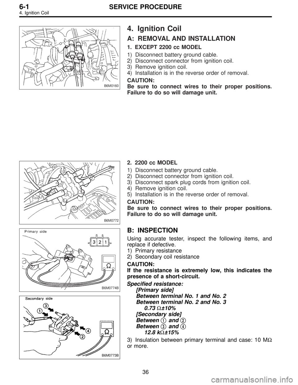
B: INSPECTION
Using accurate tester, inspect the following items, and
replace if defective.
1) Primary resistance
2) Secondary coil resistance
CAUTION:
If the resistance is extremely low, this indicates the
presence of a short-circuit.
Specified resistance:
[Primary side]
Between terminal No. 1 and No. 2
Between terminal No. 2 and No. 3
0.73Ω±10%
[Secondary side]
Between�
1and�2
Between�3and�4
12.8 kΩ±15%
3) Insulation between primary terminal and case: 10 MΩ
or more.
36
6-1SERVICE PROCEDURE
4. Ignition Coil
Page 1733 of 3342
B6M0775
5. Spark Plug Cord
A: INSPECTION
Check for:
1) Damage to cords, deformation, burning or rust forma-
tion of terminals
2) Resistance values of cords
Resistance value:
5.12—12.34 kΩ
G6M0095
6. Ignitor
A: REMOVAL AND INSTALLATION
1) Disconnect battery ground cable.
B6M0161
2) Disconnect connector from ignitor.
3) Remove screws which hold ignitor onto body.
4) Installation is in the reverse order of removal.
37
6-1SERVICE PROCEDURE
5. Spark Plug Cord - 6. Ignitor
Page 1734 of 3342
B6M0775
5. Spark Plug Cord
A: INSPECTION
Check for:
1) Damage to cords, deformation, burning or rust forma-
tion of terminals
2) Resistance values of cords
Resistance value:
5.12—12.34 kΩ
G6M0095
6. Ignitor
A: REMOVAL AND INSTALLATION
1) Disconnect battery ground cable.
B6M0161
2) Disconnect connector from ignitor.
3) Remove screws which hold ignitor onto body.
4) Installation is in the reverse order of removal.
37
6-1SERVICE PROCEDURE
5. Spark Plug Cord - 6. Ignitor
Page 1739 of 3342

1. Precaution
�Before disassembling or reassembling parts, always
disconnect battery ground cable. When repairing
radio, control modules, etc. which are provided with
memory functions, record memory contents before
disconnecting battery ground cable. Otherwise, these
contents are cancelled upon disconnection.
�Reassemble parts in reverse order of disassembly
procedure unless otherwise indicated.
�Adjust parts to specifications contained in this
manual if so designated.
�Connect connectors and hoses securely during
reassembly.
�After reassembly, ensure functional parts operate
smoothly.
CAUTION:
�Airbag system wiring harness is routed near the
electrical parts and switch.
�All Airbag system wiring harness and connectors
are colored yellow. Do not use electrical test equip-
ment on these circuit.
�Be careful not to damage Airbag system wiring har-
ness when servicing the ignition key cylinder.
G6M0102
2. Battery
A: REMOVAL AND INSTALLATION
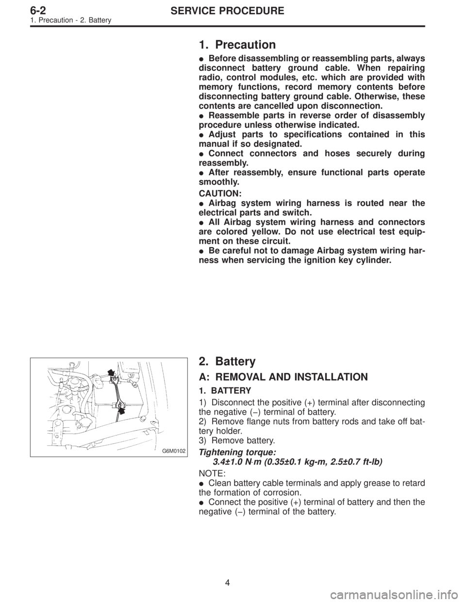
1. BATTERY
1) Disconnect the positive (+) terminal after disconnecting
the negative (�) terminal of battery.
2) Remove flange nuts from battery rods and take off bat-
tery holder.
3) Remove battery.
Tightening torque:
3.4±1.0 N⋅m (0.35±0.1 kg-m, 2.5±0.7 ft-lb)
NOTE:
�Clean battery cable terminals and apply grease to retard
the formation of corrosion.
�Connect the positive (+) terminal of battery and then the
negative (�) terminal of the battery.
4
6-2SERVICE PROCEDURE
1. Precaution - 2. Battery
Page 1740 of 3342

1. Precaution
�Before disassembling or reassembling parts, always
disconnect battery ground cable. When repairing
radio, control modules, etc. which are provided with
memory functions, record memory contents before
disconnecting battery ground cable. Otherwise, these
contents are cancelled upon disconnection.
�Reassemble parts in reverse order of disassembly
procedure unless otherwise indicated.
�Adjust parts to specifications contained in this
manual if so designated.
�Connect connectors and hoses securely during
reassembly.
�After reassembly, ensure functional parts operate
smoothly.
CAUTION:
�Airbag system wiring harness is routed near the
electrical parts and switch.
�All Airbag system wiring harness and connectors
are colored yellow. Do not use electrical test equip-
ment on these circuit.
�Be careful not to damage Airbag system wiring har-
ness when servicing the ignition key cylinder.
G6M0102
2. Battery
A: REMOVAL AND INSTALLATION
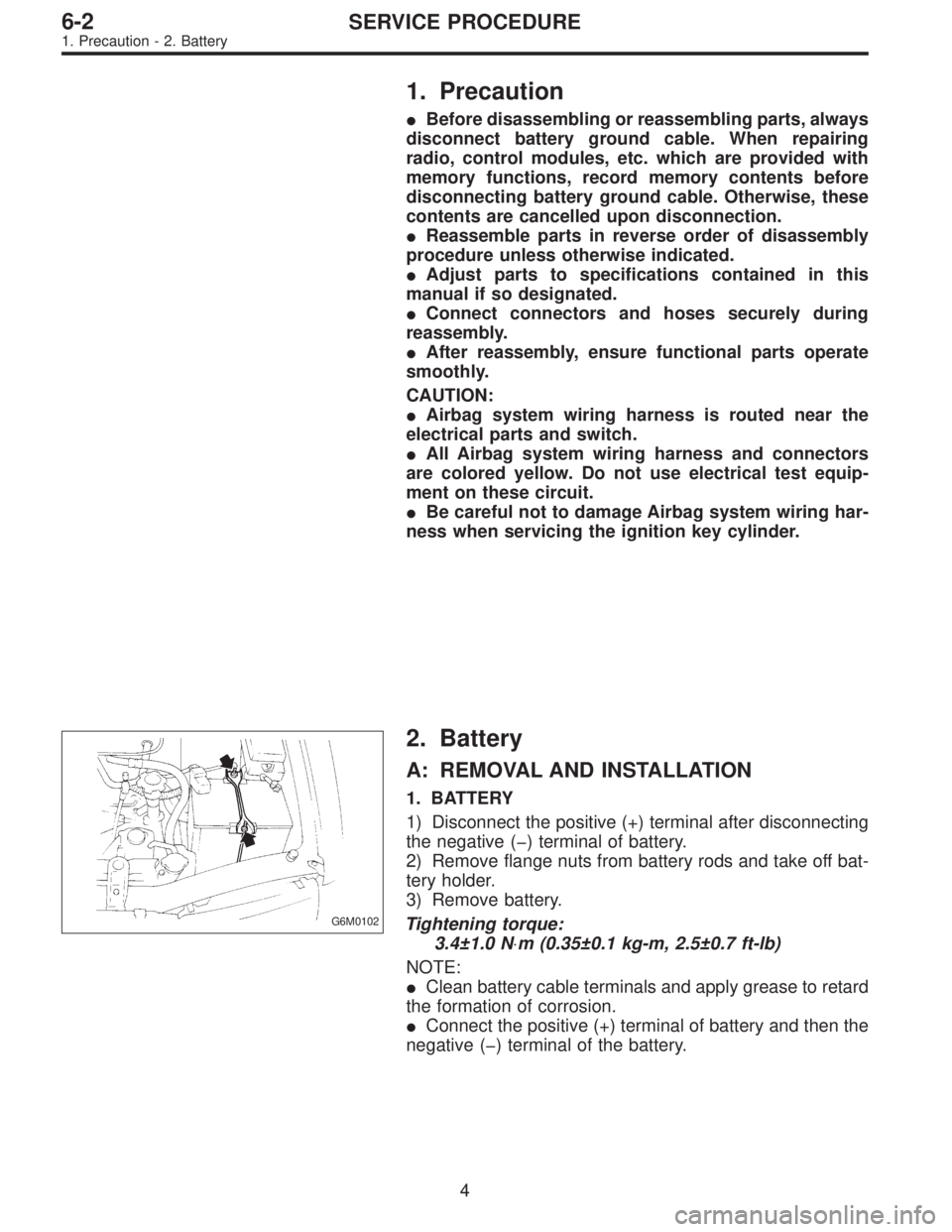
1. BATTERY
1) Disconnect the positive (+) terminal after disconnecting
the negative (�) terminal of battery.
2) Remove flange nuts from battery rods and take off bat-
tery holder.
3) Remove battery.
Tightening torque:
3.4±1.0 N⋅m (0.35±0.1 kg-m, 2.5±0.7 ft-lb)
NOTE:
�Clean battery cable terminals and apply grease to retard
the formation of corrosion.
�Connect the positive (+) terminal of battery and then the
negative (�) terminal of the battery.
4
6-2SERVICE PROCEDURE
1. Precaution - 2. Battery