Page 906 of 3342
�Available retaining platesPart No. Thickness mm (in)
31567AA190
31567AA200
31567AA210
31567AA220
31567AA230
31567AA240
31567AA250
31567AA2603.6 (0.142)
3.8 (0.150)
4.0 (0.157)
4.2 (0.165)
4.4 (0.173)
4.6 (0.181)
4.8 (0.189)
5.0 (0.197)
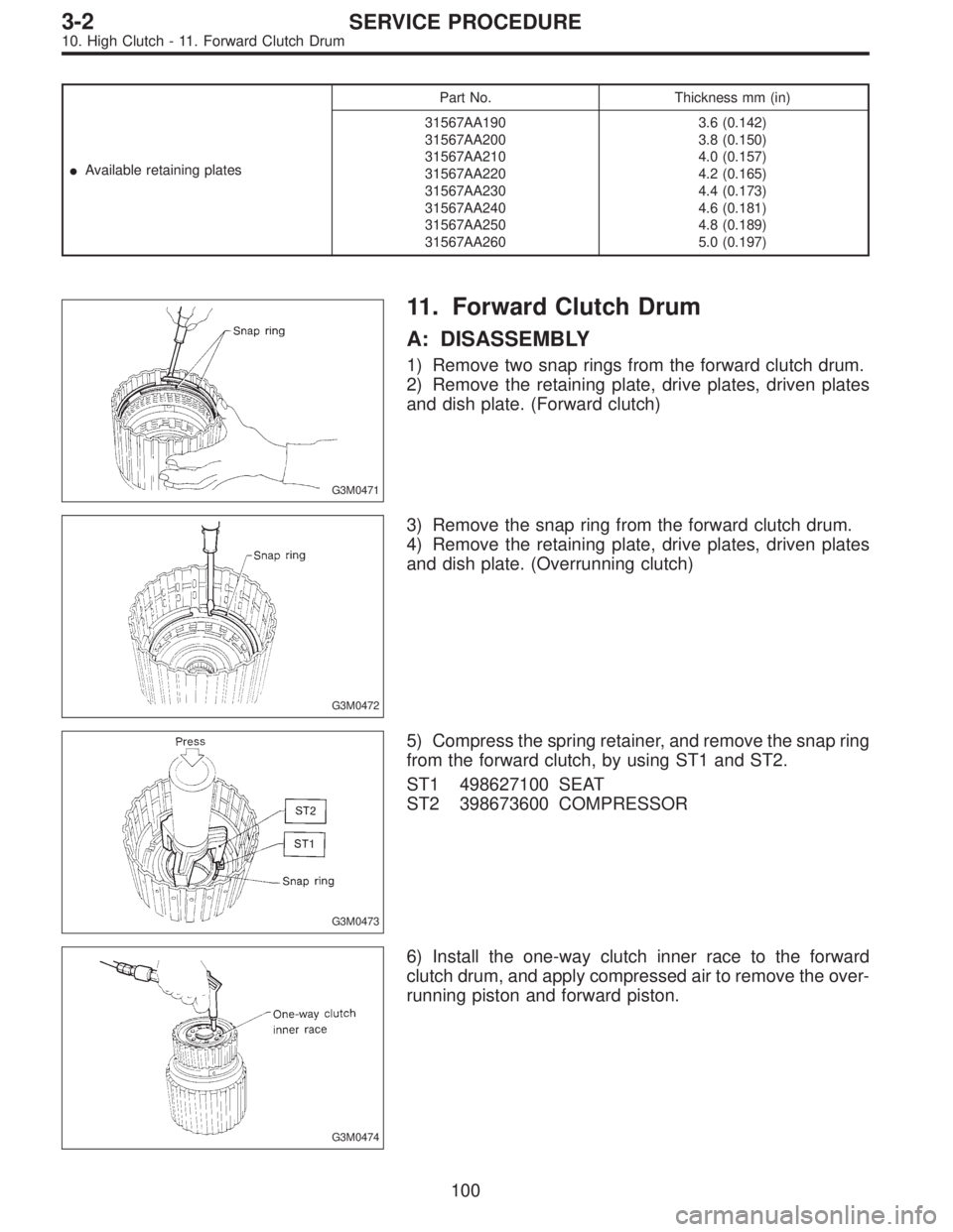
G3M0471
11. Forward Clutch Drum
A: DISASSEMBLY
1) Remove two snap rings from the forward clutch drum.
2) Remove the retaining plate, drive plates, driven plates
and dish plate. (Forward clutch)
G3M0472
3) Remove the snap ring from the forward clutch drum.
4) Remove the retaining plate, drive plates, driven plates
and dish plate. (Overrunning clutch)
G3M0473
5) Compress the spring retainer, and remove the snap ring
from the forward clutch, by using ST1 and ST2.
ST1 498627100 SEAT
ST2 398673600 COMPRESSOR
G3M0474
6) Install the one-way clutch inner race to the forward
clutch drum, and apply compressed air to remove the over-
running piston and forward piston.
100
3-2SERVICE PROCEDURE
10. High Clutch - 11. Forward Clutch Drum
Page 917 of 3342
G3M0501
3) Install the driven plates, drive plates, and pressure
plate, and secure with a snap ring with ST1, ST2 and a
press.
ST1 398673600 COMPRESSOR
ST2 498627000 SEAT
G3M0502
4) Apply compressed air to see if the assembled parts
move smoothly.
G3M0503
5) Check the clearance.
Standard value:
0.2—0.6 mm (0.008—0.024 in)
Allowable limit:
1.6 mm (0.063 in)
If the clearance is not within the specified range, select a
proper pressure plate.
NOTE:
Before measuring clearance, place the same thickness of
shim on both sides to prevent pressure plate from tilting.
�Available pressure platesPart No. Thickness mm (in)
31593AA151
31593AA161
31593AA171
31593AA1813.3 (0.130)
3.7 (0.146)
4.1 (0.161)
4.5 (0.177)
G3M0505
6) Press-fit the ball bearing with ST.
ST 899580100 INSTALLER
111
3-2SERVICE PROCEDURE
15. Transfer Clutch
Page 950 of 3342
4. CHECK FOR THE AWD FUNCTION
If“tight-corner braking”occurs when the steering wheel is
fully turned at low speed:
1) Determine the applicable trouble code and check the
corresponding duty solenoid C (transfer) for improper
operation.
2) If the solenoid is operating properly, check transfer
clutch pressure.
3) If oil pressure is normal but“tight-corner braking”
occurs:
Check the transfer control valve for sticking, and the trans-
fer clutch facing for wear.
44
3-2SERVICE PROCEDURE
3. Performance Test
Page 974 of 3342
 Apply compressed air intermittently to check for
operation.
G3M0406
(3) Check the clearance. (Selection of retaining plate)
Standard value:
1.1—1.7 mm (0.043—0.067 in)
Allowable limit:")
G3M0405
(2) Apply compressed air intermittently to check for
operation.
G3M0406
(3) Check the clearance. (Selection of retaining plate)
Standard value:
1.1—1.7 mm (0.043—0.067 in)
Allowable limit:
2.7 mm (0.106 in)
NOTE:
Before measuring clearance, place the same thickness of
shim on both sides to prevent retaining plate from tilting.
�Available retaining platesPart No. Thickness mm (in)
31667AA180
31667AA190
31667AA200
31667AA210
31667AA220
31667AA230
31667AA240
31667AA2506.5 (0.256)
6.8 (0.268)
7.1 (0.280)
7.4 (0.291)
7.7 (0.303)
8.0 (0.315)
8.2 (0.323)
8.4 (0.331)
B3M0404A
11) Install the forward clutch drum.
(1) Install carefully while rotating the drum slowly pay-
ing special attention not to damage the seal ring.
(2) Installation is complete when the drum recedes 2.5
mm (0.098 in) from the inner race surface.
G3M0408
12) Assemble the overrunning clutch hub.
CAUTION:
Install thrust needle bearing in the correct direction.
NOTE:
�Join the thrust needle bearing and thrust washer with
vaseline, and then install them together.
�Make sure that the splines are engaged correctly.
68
3-2SERVICE PROCEDURE
4. Overall Transmission
Page 1004 of 3342

C: ASSEMBLY
G3M0909
�1Reverse clutch drum
�
2Lip seal
�
3Reverse clutch piston
�
4Lathe cut seal ring�
5Spring
�
6Spring retainer
�
7Snap ring�
8Dish plate
�
9Driven plate
�
10Drive plate�
11Retaining plate
�
12Snap ring
�
13High clutch drum
1) Using the ST1, ST2 and ST3 as those used in
disassembling, assemble piston�
3the springs�5, spring
retainer�
6and snap ring�7.
ST1 398673600 COMPRESSOR
ST2 398177700 INSTALLER
ST3 399893600 PLIERS
2) Assemble the dish plate�
8, driven plates�9, drive
plates�
10and retaining plate�11in that order and attach the
snap ring�
12.
NOTE:
Pay attention to the orientation of the dish plate.
3) Checking operation:
Apply compressed air intermittently to the oil hole, and
check the reverse clutch for smooth operation.
4) Measuring clearance (Retaining plate selection):
Standard value:
0.5—0.8 mm (0.020—0.031 in)
Allowable limit:
1.2 mm (0.047 in)
NOTE:
Before measuring clearance, place the same thickness of
shim on both sides to prevent retaining plate from tilting.
�Available retaining platesPart No. Thickness mm (in)
31567AA350
31567AA360
31567AA370
31567AA380
31567AA390
31567AA4004.6 (0.181)
4.8 (0.189)
5.0 (0.197)
5.2 (0.205)
5.4 (0.213)
5.6 (0.220)
97
3-2SERVICE PROCEDURE
9. Reverse Clutch
Page 1007 of 3342
�Available retaining platesPart No. Thickness mm (in)
31567AA190
31567AA200
31567AA210
31567AA220
31567AA230
31567AA240
31567AA250
31567AA2603.6 (0.142)
3.8 (0.150)
4.0 (0.157)
4.2 (0.165)
4.4 (0.173)
4.6 (0.181)
4.8 (0.189)
5.0 (0.197)
G3M0471
11. Forward Clutch Drum
A: DISASSEMBLY
1) Remove two snap rings from the forward clutch drum.
2) Remove the retaining plate, drive plates, driven plates
and dish plate. (Forward clutch)
G3M0472
3) Remove the snap ring from the forward clutch drum.
4) Remove the retaining plate, drive plates, driven plates
and dish plate. (Overrunning clutch)
G3M0473
5) Compress the spring retainer, and remove the snap ring
from the forward clutch, by using ST1 and ST2.
ST1 498627100 SEAT
ST2 398673600 COMPRESSOR
G3M0474
6) Install the one-way clutch inner race to the forward
clutch drum, and apply compressed air to remove the over-
running piston and forward piston.
100
3-2SERVICE PROCEDURE
10. High Clutch - 11. Forward Clutch Drum
Page 1008 of 3342
�Available retaining platesPart No. Thickness mm (in)
31567AA190
31567AA200
31567AA210
31567AA220
31567AA230
31567AA240
31567AA250
31567AA2603.6 (0.142)
3.8 (0.150)
4.0 (0.157)
4.2 (0.165)
4.4 (0.173)
4.6 (0.181)
4.8 (0.189)
5.0 (0.197)
G3M0471
11. Forward Clutch Drum
A: DISASSEMBLY
1) Remove two snap rings from the forward clutch drum.
2) Remove the retaining plate, drive plates, driven plates
and dish plate. (Forward clutch)
G3M0472
3) Remove the snap ring from the forward clutch drum.
4) Remove the retaining plate, drive plates, driven plates
and dish plate. (Overrunning clutch)
G3M0473
5) Compress the spring retainer, and remove the snap ring
from the forward clutch, by using ST1 and ST2.
ST1 498627100 SEAT
ST2 398673600 COMPRESSOR
G3M0474
6) Install the one-way clutch inner race to the forward
clutch drum, and apply compressed air to remove the over-
running piston and forward piston.
100
3-2SERVICE PROCEDURE
10. High Clutch - 11. Forward Clutch Drum
Page 1020 of 3342
G3M0501
3) Install the driven plates, drive plates, and pressure
plate, and secure with a snap ring with ST1, ST2 and a
press.
ST1 398673600 COMPRESSOR
ST2 498627000 SEAT
G3M0502
4) Apply compressed air to see if the assembled parts
move smoothly.
G3M0503
5) Check the clearance.
Standard value:
0.2—0.6 mm (0.008—0.024 in)
Allowable limit:
1.6 mm (0.063 in)
If the clearance is not within the specified range, select a
proper pressure plate.
NOTE:
Before measuring clearance, place the same thickness of
shim on both sides to prevent pressure plate from tilting.
�Available pressure platesPart No. Thickness mm (in)
31593AA151
31593AA161
31593AA171
31593AA1813.3 (0.130)
3.7 (0.146)
4.1 (0.161)
4.5 (0.177)
G3M0505
6) Press-fit the ball bearing with ST.
ST 899580100 INSTALLER
111
3-2SERVICE PROCEDURE
15. Transfer Clutch

 Install the driven plates, drive plates, and pressure
plate, and secure with a snap ring with ST1, ST2 and a
press.
ST1 398673600 COMPRESSOR
ST2 498627000 SEAT
G3M0502
4) Apply compressed a")
 Determine the applicable trouble code and check the
corresponding duty solenoi")

 Install the driven plates, drive plates, and pressure
plate, and secure with a snap ring with ST1, ST2 and a
press.
ST1 398673600 COMPRESSOR
ST2 498627000 SEAT
G3M0502
4) Apply compressed a")