Page 1896 of 3342
B2M0754
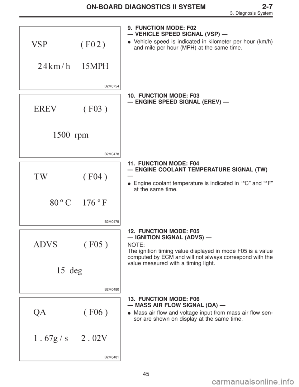
9. FUNCTION MODE: F02
—VEHICLE SPEED SIGNAL (VSP)—
�Vehicle speed is indicated in kilometer per hour (km/h)
and mile per hour (MPH) at the same time.
B2M0478
10. FUNCTION MODE: F03
—ENGINE SPEED SIGNAL (EREV)—
B2M0479
11. FUNCTION MODE: F04
—ENGINE COOLANT TEMPERATURE SIGNAL (TW)
—
�Engine coolant temperature is indicated in“°C”and“°F”
at the same time.
B2M0480
12. FUNCTION MODE: F05
—IGNITION SIGNAL (ADVS)—
NOTE:
The ignition timing value displayed in mode F05 is a value
computed by ECM and will not always correspond with the
value measured with a timing light.
B2M0481
13. FUNCTION MODE: F06
—MASS AIR FLOW SIGNAL (QA)—
�Mass air flow and voltage input from mass air flow sen-
sor are shown on display at the same time.
45
2-7ON-BOARD DIAGNOSTICS II SYSTEM
3. Diagnosis System
Page 1904 of 3342

LED No. Signal name Display
1——
2——
3 Neutral switch NT
4——
5——
6——
7 Test mode connector UD
8 Identification of AT model AT
9 Ignition switch IG
0——
——NT——
—UD AT IG—
1
2345
67890
41. FUNCTION MODE: FA0
—ON↔OFF SIGNAL—
Requirement for LED“ON”.
LED No. 3�On MT model, gear position is in neutral.
�On AT model, shift position is in“P”or“N”.
LED No. 7 Test mode connector is connected.
LED No. 8 Vehicle is AT model.
LED No. 9 Ignition switch is turned ON.
LED No. Signal name Display
1 Radiator fan relay 2 R2
2 Knock signal KS
3Purge control solenoid
valveCN
4 Fuel pump relay FP
5——
6 Radiator fan relay 1 R1
7 A/C relay AR
8 A/C switch AC
9——
0——
R2 KS CN FP—
R1 AR AC——
1
2345
67890
42. FUNCTION MODE: FA1
—ON↔OFF SIGNAL—
Requirement for LED“ON”.
LED No. 1 Radiator fan relay 2 is turned ON.
LED No. 2 Engine is knocking.
LED No. 3 Purge control solenoid valve is in function.
LED No. 4 Fuel pump relay is turned ON.
LED No. 6 Radiator fan relay 1 is turned ON.
LED No. 7 A/C relay is turned ON.
LED No. 8 A/C switch is turned ON.
NOTE:
�When LED No. 1, 3, 4, 6 and 7 blinks with the test mode
connector connected and the ignition switch turned to ON,
the corresponding part is functioning properly.
�When LED No. 4 illuminates for only 2 seconds after the
ignition switch is turned to ON, (and then goes out), the
corresponding part is functioning properly.
�LED No. 3 is applicable only to the models not equipped
with enhanced evaporative emission control system.
53
2-7ON-BOARD DIAGNOSTICS II SYSTEM
3. Diagnosis System
Page 1906 of 3342

LED No. Signal name Display
1 Catalyst CA
2 EGR system E1
3California model
identification signalFC
4——
5——
6——
7——
8 Rear oxygen sensor signal OR
9 Front oxygen sensor signal O2
0——
CA E1 FC——
——OR O2—
1
2345
67890
45. FUNCTION MODE: FA4
—ON↔OFF SIGNAL—
Requirement for LED“ON”.
LED No. 1 Diagnosis of catalyzer is finished.
LED No. 2 Diagnosis of EGR system is finished.
LED No. 3 Vehicle is Federal specifications.
LED No. 8 Rear oxygen sensor mixture ratio is rich.
LED No. 9 Front oxygen sensor mixture ratio is rich.
LED No. Signal name Display
1——
2——
3——
4——
5——
6 Vent control solenoid valve AL
7 EGR solenoid valve ER
8Pressure control solenoid
valvePC
9——
0——
—————
AL ER PC——
1
2345
67890
46. FUNCTION MODE: FA5
—ON↔OFF SIGNAL—
Requirement for LED“ON”.
LED No. 6 Vent control solenoid valve is in function.
LED No. 7 EGR solenoid valve is in function.
LED No. 8 Pressure control solenoid valve is in func-
tion.
NOTE:
When LED No. 6, 7 and 8 blinks with the test mode con-
nector connected and the ignition switch turned to ON, the
corresponding part is functioning properly.
55
2-7ON-BOARD DIAGNOSTICS II SYSTEM
3. Diagnosis System
Page 1980 of 3342
 LIST
DTC
No.Abbreviation
(Subaru Select Monitor)Item Page
P0101 QA
—RLOW Mass air flow sensor circuit range/p")
10. Diagnostic Chart with Trouble Code
for LHD Vehicles
A: DIAGNOSTIC TROUBLE CODE (DTC) LIST
DTC
No.Abbreviation
(Subaru Select Monitor)Item Page
P0101 QA
—RLOW Mass air flow sensor circuit range/performance problem (low input) 132
P0102 QA
—LOW Mass air flow sensor circuit low input 134
P0103 QA
—HI Mass air flow sensor circuit high input 138
P0106 PS
—R2 Pressure sensor circuit range/performance problem 141
P0107 P
—SLOW Pressure sensor circuit low input 145
P0108 P
—SHI Pressure sensor circuit high input 149
P0116 TW
—LOW Engine coolant temperature sensor circuit low input 154
P0117 TW
—HI Engine coolant temperature sensor circuit high input 157
P0121 TH
—RHI Throttle position sensor circuit range/performance problem (high input) 160
P0122 THV
—LOW Throttle position sensor circuit low input 162
P0123 THV
—HI Throttle position sensor circuit high input 167
P0125 TW
—CL Insufficient coolant temperature for closed loop fuel control 170
P0130 FO2
—V Front oxygen sensor circuit malfunction 172
P0133 FO2
—R Front oxygen sensor circuit slow response 175
P0135 FO2H Front oxygen sensor heater circuit malfunction 177
P0136 RO2
—V Rear oxygen sensor circuit malfunction 181
P0139 RO2
—R Rear oxygen sensor circuit slow response 184
P0141 RO2H Rear oxygen sensor heater circuit malfunction 186
P0170 FUEL Fuel trim malfunction 190
P0181 TNKT
—F Fuel temperature sensor A circuit range/performance problem 195
P0182 TNKT
—LOW Fuel temperature sensor A circuit low input 197
P0183 TNKT
—HI Fuel temperature sensor A circuit high input 200
P0261 INJ1 Fuel injector circuit low input - #1 203
P0262 INJ1
—HI Fuel injector circuit high input - #1 207
P0264 INJ2 Fuel injector circuit low input - #2 203
P0265 INJ2
—HI Fuel injector circuit high input - #2 207
P0267 INJ3 Fuel injector circuit low input - #3 203
P0268 INJ3
—HI Fuel injector circuit high input - #3 207
P0270 INJ4 Fuel injector circuit low input - #4 203
P0271 INJ4
—HI Fuel injector circuit high input - #4 207
P0301 MIS
—1 Cylinder 1 misfire detected 211
P0302 MIS
—2 Cylinder 2 misfire detected 211
P0303 MIS
—3 Cylinder 3 misfire detected 211
P0304 MIS
—4 Cylinder 4 misfire detected 211
P0325 KNOCK Knock sensor circuit malfunction 219
P0335 CRANK Crankshaft position sensor circuit malfunction 222
P0336 CRANK
—R Crankshaft position sensor circuit range/performance problem 225
P0340 CAM Camshaft position sensor circuit malfunction 227
129
2-7ON-BOARD DIAGNOSTICS II SYSTEM
10. Diagnostic Chart with Trouble Code for LHD Vehicles
Page 2026 of 3342
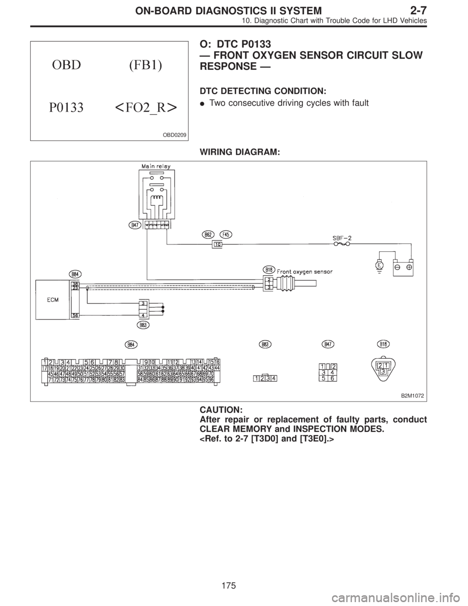
OBD0209
O: DTC P0133
—FRONT OXYGEN SENSOR CIRCUIT SLOW
RESPONSE—
DTC DETECTING CONDITION:
�Two consecutive driving cycles with fault
WIRING DIAGRAM:
B2M1072
CAUTION:
After repair or replacement of faulty parts, conduct
CLEAR MEMORY and INSPECTION MODES.
175
2-7ON-BOARD DIAGNOSTICS II SYSTEM
10. Diagnostic Chart with Trouble Code for LHD Vehicles
Page 2035 of 3342
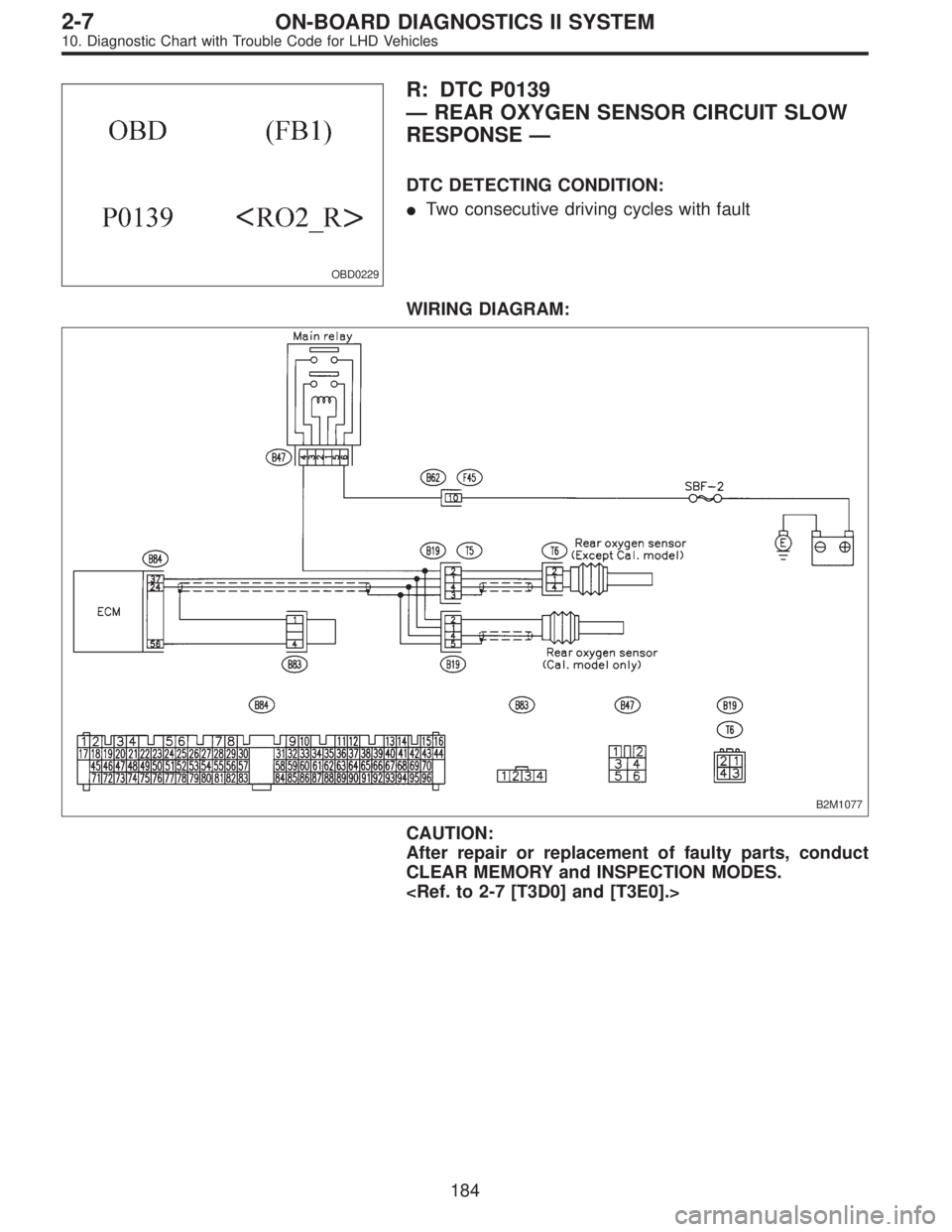
OBD0229
R: DTC P0139
—REAR OXYGEN SENSOR CIRCUIT SLOW
RESPONSE—
DTC DETECTING CONDITION:
�Two consecutive driving cycles with fault
WIRING DIAGRAM:
B2M1077
CAUTION:
After repair or replacement of faulty parts, conduct
CLEAR MEMORY and INSPECTION MODES.
184
2-7ON-BOARD DIAGNOSTICS II SYSTEM
10. Diagnostic Chart with Trouble Code for LHD Vehicles
Page 2274 of 3342
 LIST
DTC
No.Abbreviation
(Subaru Select Monitor)Item Page
P0101 QA
—RLOW Mass air flow sensor circuit range/p")
11. Diagnostic Chart with Trouble Code
for RHD Vehicles
A: DIAGNOSTIC TROUBLE CODE (DTC) LIST
DTC
No.Abbreviation
(Subaru Select Monitor)Item Page
P0101 QA
—RLOW Mass air flow sensor circuit range/performance problem (low input) 426
P0102 QA
—LOW Mass air flow sensor circuit low input 427
P0103 QA
—HI Mass air flow sensor circuit high input 428
P0106 PS
—R2 Pressure sensor circuit range/performance problem 429
P0107 P
—SLOW Pressure sensor circuit low input 430
P0108 P
—SHI Pressure sensor circuit high input 431
P0116 TW
—LOW Engine coolant temperature sensor circuit low input 432
P0117 TW
—HI Engine coolant temperature sensor circuit high input 433
P0121 TH
—RHI Throttle position sensor circuit range/performance problem (high input) 434
P0122 THV
—LOW Throttle position sensor circuit low input 435
P0123 THV
—HI Throttle position sensor circuit high input 436
P0125 TW
—CL Insufficient coolant temperature for closed loop fuel control 437
P0130 FO2
—V Front oxygen sensor circuit malfunction 438
P0133 FO2
—R Front oxygen sensor circuit slow response 439
P0135 FO2H Front oxygen sensor heater circuit malfunction 440
P0136 RO2
—V Rear oxygen sensor circuit malfunction 441
P0139 RO2
—R Rear oxygen sensor circuit slow response 442
P0141 RO2H Rear oxygen sensor heater circuit malfunction 443
P0170 FUEL Fuel trim malfunction 444
P0181 TNKT
—F Fuel temperature sensor A circuit range/performance problem 445
P0182 TNKT
—LOW Fuel temperature sensor A circuit low input 447
P0183 TNKT
—HI Fuel temperature sensor A circuit high input 450
P0261 INJ1 Fuel injector circuit low input - #1 453
P0262 INJ1
—HI Fuel injector circuit high input - #1 455
P0264 INJ2 Fuel injector circuit low input - #2 453
P0265 INJ2
—HI Fuel injector circuit high input - #2 455
P0267 INJ3 Fuel injector circuit low input - #3 453
P0268 INJ3
—HI Fuel injector circuit high input - #3 455
P0270 INJ4 Fuel injector circuit low input - #4 453
P0271 INJ4
—HI Fuel injector circuit high input - #4 455
P0301 MIS
—1 Cylinder 1 misfire detected 457
P0302 MIS
—2 Cylinder 2 misfire detected 457
P0303 MIS
—3 Cylinder 3 misfire detected 457
P0304 MIS
—4 Cylinder 4 misfire detected 457
P0325 KNOCK Knock sensor circuit malfunction 459
P0335 CRANK Crankshaft position sensor circuit malfunction 460
P0336 CRANK
—R Crankshaft position sensor circuit range/performance problem 461
P0340 CAM Camshaft position sensor circuit malfunction 462
423
2-7ON-BOARD DIAGNOSTICS II SYSTEM
11. Diagnostic Chart with Trouble Code for RHD Vehicles
Page 2290 of 3342
OBD0209
O: DTC P0133
—FRONT OXYGEN SENSOR CIRCUIT SLOW
RESPONSE—
WIRING DIAGRAM:
B2M1150
NOTE:
Check front oxygen sensor circuit.
439
2-7ON-BOARD DIAGNOSTICS II SYSTEM
11. Diagnostic Chart with Trouble Code for RHD Vehicles
![SUBARU LEGACY 1997 Service Repair Manual OBD0209
O: DTC P0133
—FRONT OXYGEN SENSOR CIRCUIT SLOW
RESPONSE—
WIRING DIAGRAM:
B2M1150
NOTE:
Check front oxygen sensor circuit.
<Ref. to 2-7 [T10O0].>
439
2-7ON-BOARD DIAGNOSTICS II SYSTEM
11. D](/manual-img/17/57434/w960_57434-2289.png "SUBARU LEGACY 1997 Service Repair Manual OBD0209
O: DTC P0133
—FRONT OXYGEN SENSOR CIRCUIT SLOW
RESPONSE—
WIRING DIAGRAM:
B2M1150
NOTE:
Check front oxygen sensor circuit.
<Ref. to 2-7 [T10O0].>
439
2-7ON-BOARD DIAGNOSTICS II SYSTEM
11. D")