Page 1288 of 3342
Model Sedan Wagon
Engine (cc) 2500
Driving system AWD
GT LSi GT LSi OUTBACK
Hill holder—————
Parking
brakeType Mechanical on rear brakes, drum in disc
Effective drum diameter
mm (in)170 (6.69)
Lining dimensions
(length x width x thickness)
mm (in)162.6 x 30.0 x 3.2 (6.40 x 1.181 x 0.126)
Clearance adjustment Manual adjustment
Master
cylinderType Tandem
Effective diameter
mm (in)26.99 (1-1/16)
Reservoir type Sealed type
Brake fluid reservoir capacity
cm
3(cu in)190 (11.59)
Brake
boosterType Vacuum suspended
Effective diameter
mm (in)205 + 230 (8.07 + 9.06)
Proportioning
valveSplit point
kPa (kg/cm
2, psi)3,678 (37.5, 533)
Reducing ratio 0.3
Brake line Dual circuit system
ABSSTD
8
4-4SPECIFICATIONS AND SERVICE DATA
1. Brakes
Page 1702 of 3342
G6M0095
1. Starter
A: REMOVAL AND INSTALLATION
1) Disconnect battery ground cable.
G2M0309
2) Disconnect connector and terminal from starter.
3) Remove starter from transmission.
4) Installation is in the reverse order of removal.
Tightening torque:
50±4 N⋅m (5.1±0.4 kg-m, 36.9±2.9 ft-lb)
B: TEST
1. MAGNETIC SWITCH
CAUTION:
�The following magnetic switch tests should be per-
formed with specified voltage applied.
�Each test should be conducted within 3 to 5 sec-
onds. Power to be furnished should be one-half the
rated voltage.
B6M0415A
1) Pull-in test
Connect two battery negative leads onto magnetic switch
body and terminal C respectively. Then connect battery
positive lead onto terminal 50. Pinion should extend when
lead connections are made.
B6M0416A
2) Holding-in test
Disconnect lead from terminal C with pinion extended. Pin-
ion should be held in the extended position.
7
6-1SERVICE PROCEDURE
1. Starter
Page 1703 of 3342
 Return test
Connect two battery negative leads onto terminal 50 and
onto switch body respectively. Then connect battery posi-
tive lead onto terminal C. Next, disconnect lead from ter-
min")
B6M0417A
3) Return test
Connect two battery negative leads onto terminal 50 and
onto switch body respectively. Then connect battery posi-
tive lead onto terminal C. Next, disconnect lead from ter-
minal 50. Pinion should return immediately.
2. PERFORMANCE TEST
The starter is required to produce a large torque and high
rotating speed, but these starter characteristics vary with
the capacity of the battery. It is therefore important to use
a battery with the specified capacity whenever testing the
starter.
The starter should be checked for the following three items:
1. No-load test
Measure the maximum rotating speed and current under a
no-load state.
2. Load test
Measure the magnitude of current needed to generate the
specified torque and rotating speed.
3. Stall test
Measure the torque and current when the armature is
locked.
B6M0418A
1) No-load test
Run single starter under no-load state, and measure its
rotating speed, voltage, and current, using the specified
battery. Measured values must meet the following stan-
dards:
No-load test (Standard):
Voltage/Current
11 V/90 A, or more
Rotating speed
TN128000-8311: 3,000 rpm, or more
TN128000-8321: 3,350 rpm, or more
8
6-1SERVICE PROCEDURE
1. Starter
Page 1741 of 3342
 External parts
Check for the existence of dirt or cracks on the battery
case, top cover, vent plugs, and terminal posts. If
necessary, clean with water and wipe with a dry")
B: INSPECTION
1. BATTERY
1) External parts
Check for the existence of dirt or cracks on the battery
case, top cover, vent plugs, and terminal posts. If
necessary, clean with water and wipe with a dry cloth.
Apply a thin coat of grease on the terminal posts to prevent
corrosion.
2) Electrolyte level
Check the electrolyte level in each cell. If the level is below
MIN LEVEL, bring the level to MAX LEVEL by pouring dis-
tilled water into the battery cell. Do not fill beyond MAX
LEVEL.
WARNING:
�Electrolyte has toxicity; be careful handling the
fluid.
�Avoid contact with skin, eyes or clothing. Especially
at contact with eyes, blush with water for 15 minutes
and get prompt medical attention.
�Batteries produce explosive gasses. Keep sparks,
flame, cigarettes away.
�Ventilate when charging or using in enclosed space.
�For safety, in case an explosion does occur, wear
eye protection or shield your eyes when working near
any battery. Never lean over a battery.
�Do not let battery fluid contact eyes, skin, fabrics, or
paint-work because battery fluid is corrosive acid.
�To lessen the risk of sparks, remove rings, metal
watch-bands, and other metal jewelry. Never allow
metal tools to contact the positive battery terminal and
anything connected to it while you are at the same time
in contact with any other metallic portion of the vehicle
because a short circuit will be caused.
5
6-2SERVICE PROCEDURE
2. Battery
Page 1750 of 3342
D: INSPECTION
1. COMBINATION SWITCH (ON-CAR)
1) Remove instrument panel lower cover.
2) Remove lower column cover.
B6M0238
3) Unfasten holddown clip which secures harness, and
disconnect connectors from body harness.
4) Move combination switch to respective positions and
check continuity between terminals as indicated in the fol-
lowing tables:
Lighting switch
Terminal
Switch positionc-1 c-2 c-3
OFF
Tail��
*��
Head���
Parking switch
Terminal
Switch positionc-10 c-11 c-9
OFF��
*XX
ON��
Dimmer and passing switch
Terminal
Switch positiona-3 a-2 a-1 a-4
Flash��
�
*���
Low beam��
*���
HI-beam��
12
6-2SERVICE PROCEDURE
4. Headlight
Page 1758 of 3342
B: DISASSEMBLY AND ASSEMBLY
1. COMBINATION SWITCH
Refer to 6-2 [W4C1] as for disassembly and assembly of
combination switch.
C: INSPECTION
1. COMBINATION SWITCH (ON-CAR)
1) Remove instrument panel lower cover.
2) Remove lower column cover.
B6M0238
3) Unfasten holddown clip which secures harness, and
disconnect connectors from body harness.
4) Move combination switch to respective positions and
check continuity between terminals as indicated in table
below:
Turn signal switch
Terminal
Switch positiona-5 a-7 a-6
TurnL⋅L′��
*xx
N
*xx
R⋅R′��
B6M0344
2. HAZARD SWITCH
Move hazard switch to each position and check continuity
between terminals as indicated in table below:
73910561 2
ON��
�����
OFF����
20
6-2SERVICE PROCEDURE
6. Turn Signal and Hazard Warning Light
Page 1891 of 3342
H2M1149
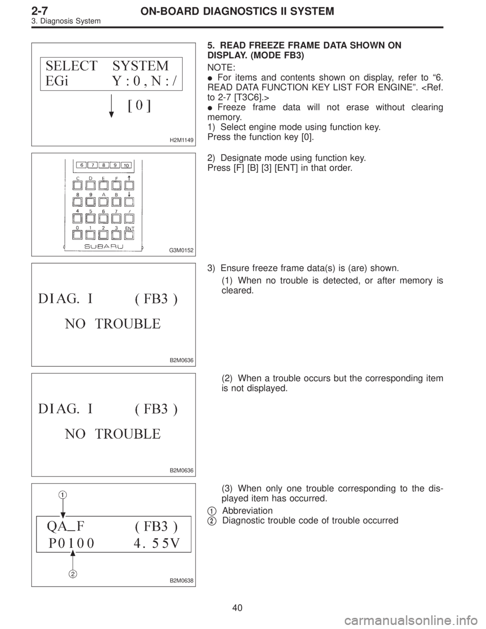
5. READ FREEZE FRAME DATA SHOWN ON
DISPLAY. (MODE FB3)
NOTE:
�For items and contents shown on display, refer to“6.
READ DATA FUNCTION KEY LIST FOR ENGINE”.
to 2-7 [T3C6].>
�Freeze frame data will not erase without clearing
memory.
1) Select engine mode using function key.
Press the function key [0].
G3M0152
2) Designate mode using function key.
Press [F] [B] [3] [ENT] in that order.
B2M0636
3) Ensure freeze frame data(s) is (are) shown.
(1) When no trouble is detected, or after memory is
cleared.
B2M0636
(2) When a trouble occurs but the corresponding item
is not displayed.
B2M0638
(3) When only one trouble corresponding to the dis-
played item has occurred.
�
1Abbreviation
�
2Diagnostic trouble code of trouble occurred
40
2-7ON-BOARD DIAGNOSTICS II SYSTEM
3. Diagnosis System
Page 1892 of 3342
B2M0649
(4) When multiple troubles corresponding to the dis-
played item are detected.
NOTE:
Freeze frame data is shown on display for 2 seconds at a
time.
41
2-7ON-BOARD DIAGNOSTICS II SYSTEM
3. Diagnosis System
 2500
Driving system AWD
GT LSi GT LSi OUTBACK
Hill holder—————
Parking
brakeType Mechanical on rear brakes, drum in disc
Effective drum diameter
mm (in)170 (6.6")
 Disconnect battery ground cable.
G2M0309
2) Disconnect connector and terminal from starter.
3) Remove starter from transmission.
4) Installation is in")

1) Remove instrument panel lower cover.
2) Remove lower column cover.
B6M0238
3) Unfasten holddown clip which secures harness, and
disconnect connectors fr")
![SUBARU LEGACY 1997 Service Repair Manual B: DISASSEMBLY AND ASSEMBLY
1. COMBINATION SWITCH
Refer to 6-2 [W4C1] as for disassembly and assembly of
combination switch.
C: INSPECTION
1. COMBINATION SWITCH (ON-CAR)
1) Remove instrument panel low](/manual-img/17/57434/w960_57434-1757.png "SUBARU LEGACY 1997 Service Repair Manual B: DISASSEMBLY AND ASSEMBLY
1. COMBINATION SWITCH
Refer to 6-2 [W4C1] as for disassembly and assembly of
combination switch.
C: INSPECTION
1. COMBINATION SWITCH (ON-CAR)
1) Remove instrument panel low")
 When multiple troubles corresponding to the dis-
played item are detected.
NOTE:
Freeze frame data is shown on display for 2 seconds at a
time.
41
2-7ON-BOARD DIAGNOSTICS II SYSTEM
3. Diag")