1997 SSANGYONG KORANDO light
[x] Cancel search: lightPage 1238 of 2053
AUTOMATIC TRANSMISSION 5A-143
SSANGYONG MY2002
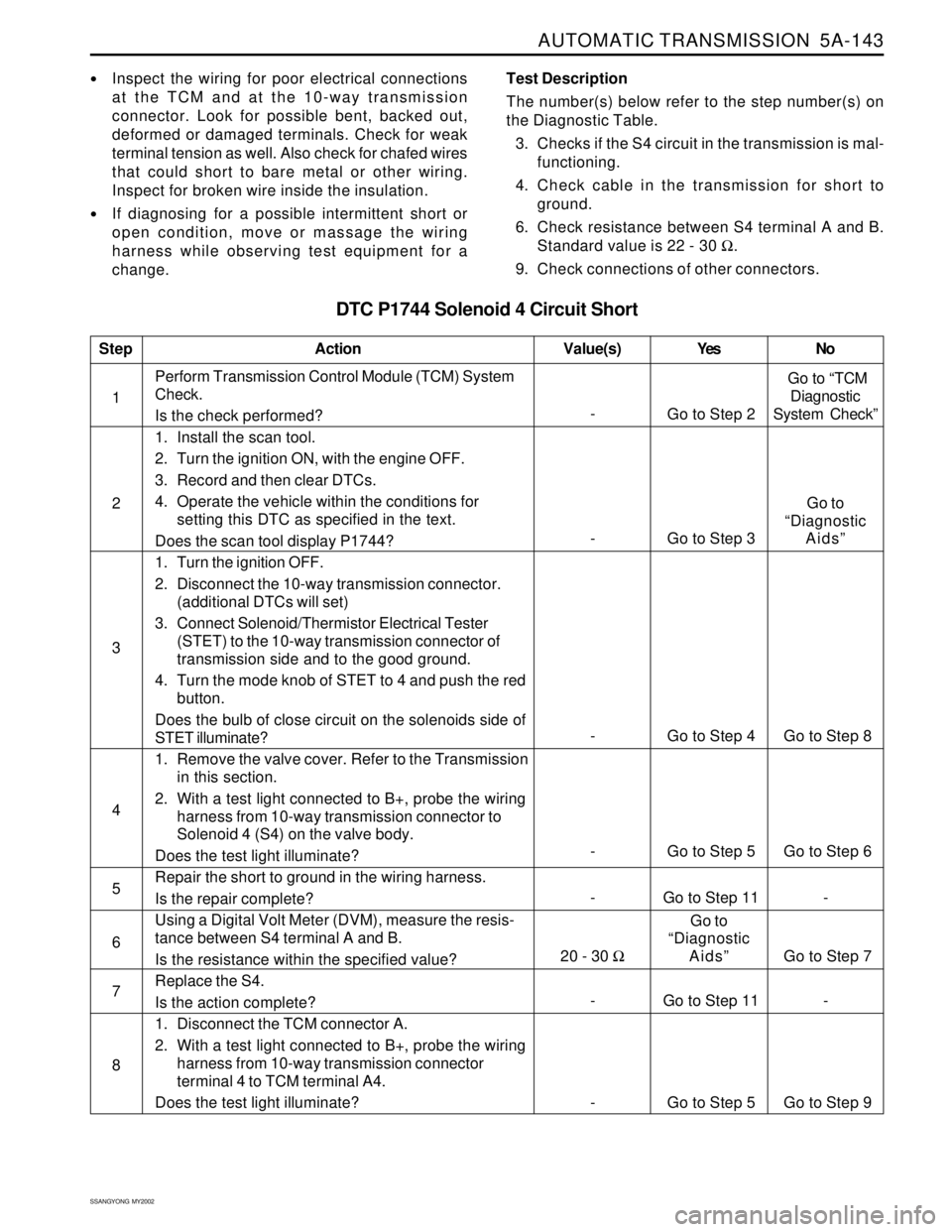
DTC P1744 Solenoid 4 Circuit Short
Inspect the wiring for poor electrical connections
at the TCM and at the 10-way transmission
connector. Look for possible bent, backed out,
deformed or damaged terminals. Check for weak
terminal tension as well. Also check for chafed wires
that could short to bare metal or other wiring.
Inspect for broken wire inside the insulation.
If diagnosing for a possible intermittent short or
open condition, move or massage the wiring
harness while observing test equipment for a
change.Test Description
The number(s) below refer to the step number(s) on
the Diagnostic Table.
3. Checks if the S4 circuit in the transmission is mal-
functioning.
4. Check cable in the transmission for short to
ground.
6. Check resistance between S4 terminal A and B.
Standard value is 22 - 30 Ω.
9. Check connections of other connectors.
- Go to Step 11 - 1Perform Transmission Control Module (TCM) System
Check.
Is the check performed?
1. Install the scan tool.
2. Turn the ignition ON, with the engine OFF.
3. Record and then clear DTCs.
4. Operate the vehicle within the conditions for
setting this DTC as specified in the text.
Does the scan tool display P1744?
1. Turn the ignition OFF.
2. Disconnect the 10-way transmission connector.
(additional DTCs will set)
3. Connect Solenoid/Thermistor Electrical Tester
(STET) to the 10-way transmission connector of
transmission side and to the good ground.
4. Turn the mode knob of STET to 4 and push the red
button.
Does the bulb of close circuit on the solenoids side of
STET illuminate?
1. Remove the valve cover. Refer to the Transmission
in this section.
2. With a test light connected to B+, probe the wiring
harness from 10-way transmission connector to
Solenoid 4 (S4) on the valve body.
Does the test light illuminate?
Repair the short to ground in the wiring harness.
Is the repair complete?
Using a Digital Volt Meter (DVM), measure the resis-
tance between S4 terminal A and B.
Is the resistance within the specified value?
Replace the S4.
Is the action complete?
1. Disconnect the TCM connector A.
2. With a test light connected to B+, probe the wiring
harness from 10-way transmission connector
terminal 4 to TCM terminal A4.
Does the test light illuminate?
StepAction Value(s) Yes No
2
3
-
Go to Step 2 Go to “TCM
Diagnostic
System Check”
- Go to Step 4 Go to Step 8
5
6 4
- Go to Step 5 Go to Step 6
- Go to Step 11 -
7
8
- Go to Step 5 Go to Step 9
- Go to Step 3Go to
“Diagnostic
Aids”
20 - 30 ΩGo to
“Diagnostic
Aids” Go to Step 7
Page 1242 of 2053
AUTOMATIC TRANSMISSION 5A-147
SSANGYONG MY2002
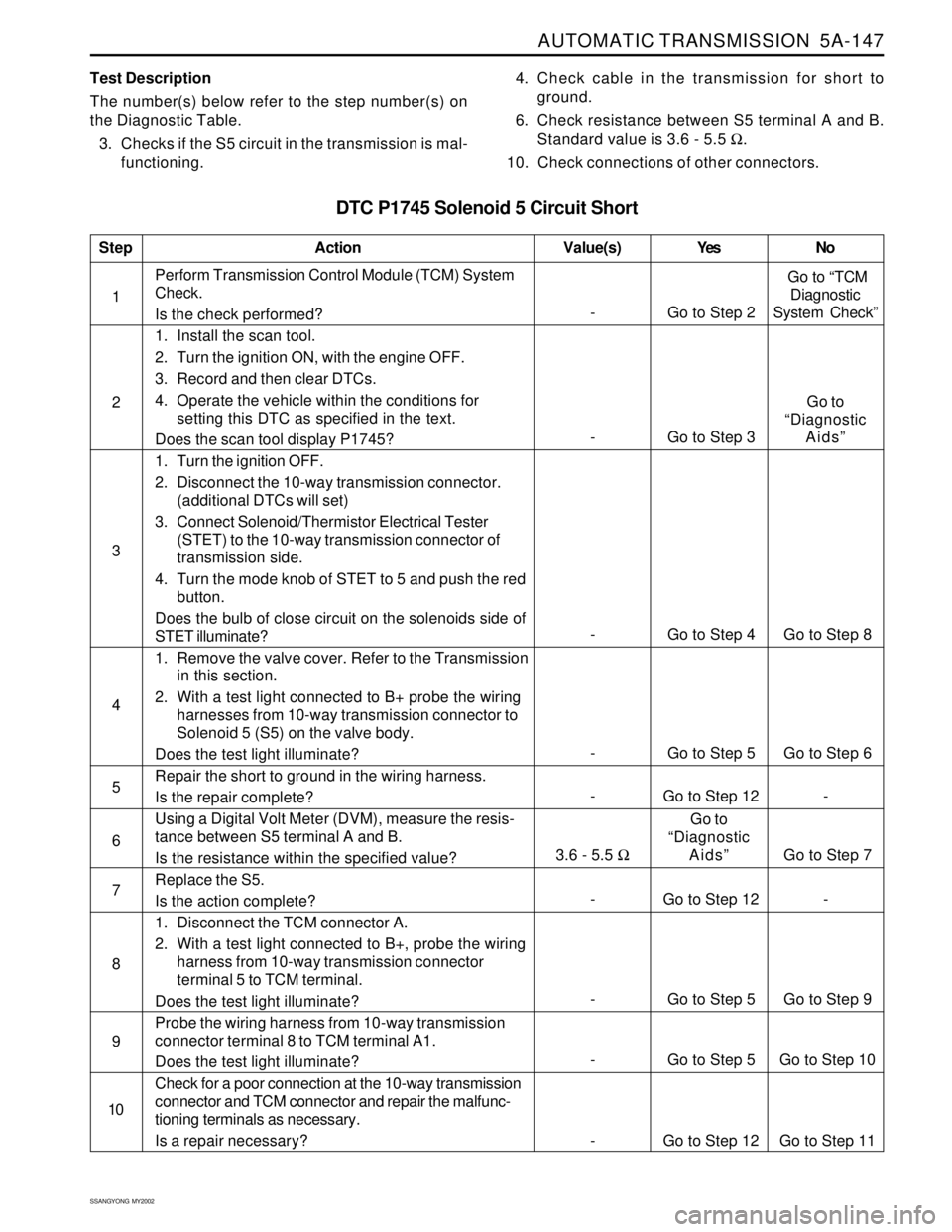
DTC P1745 Solenoid 5 Circuit Short
Test Description
The number(s) below refer to the step number(s) on
the Diagnostic Table.
3. Checks if the S5 circuit in the transmission is mal-
functioning.4. Check cable in the transmission for short to
ground.
6. Check resistance between S5 terminal A and B.
Standard value is 3.6 - 5.5 Ω.
10. Check connections of other connectors.
- Go to Step 12 - 1Perform Transmission Control Module (TCM) System
Check.
Is the check performed?
1. Install the scan tool.
2. Turn the ignition ON, with the engine OFF.
3. Record and then clear DTCs.
4. Operate the vehicle within the conditions for
setting this DTC as specified in the text.
Does the scan tool display P1745?
1. Turn the ignition OFF.
2. Disconnect the 10-way transmission connector.
(additional DTCs will set)
3. Connect Solenoid/Thermistor Electrical Tester
(STET) to the 10-way transmission connector of
transmission side.
4. Turn the mode knob of STET to 5 and push the red
button.
Does the bulb of close circuit on the solenoids side of
STET illuminate?
1. Remove the valve cover. Refer to the Transmission
in this section.
2. With a test light connected to B+ probe the wiring
harnesses from 10-way transmission connector to
Solenoid 5 (S5) on the valve body.
Does the test light illuminate?
Repair the short to ground in the wiring harness.
Is the repair complete?
Using a Digital Volt Meter (DVM), measure the resis-
tance between S5 terminal A and B.
Is the resistance within the specified value?
Replace the S5.
Is the action complete?
1. Disconnect the TCM connector A.
2. With a test light connected to B+, probe the wiring
harness from 10-way transmission connector
terminal 5 to TCM terminal.
Does the test light illuminate?
Probe the wiring harness from 10-way transmission
connector terminal 8 to TCM terminal A1.
Does the test light illuminate?
Check for a poor connection at the 10-way transmission
connector and TCM connector and repair the malfunc-
tioning terminals as necessary.
Is a repair necessary?
StepAction Value(s) Yes No
2
3
-
Go to Step 2 Go to “TCM
Diagnostic
System Check”
- Go to Step 4 Go to Step 8
5
6 4
- Go to Step 5 Go to Step 6
- Go to Step 12 -
7
8
9
- Go to Step 5 Go to Step 9
10
- Go to Step 5 Go to Step 10
- Go to Step 12 Go to Step 11
- Go to Step 3Go to
“Diagnostic
Aids”
3.6 - 5.5 ΩGo to
“Diagnostic
Aids” Go to Step 7
Page 1249 of 2053
AUTOMATIC TRANSMISSION 5A-151
SSANGYONG MY2002
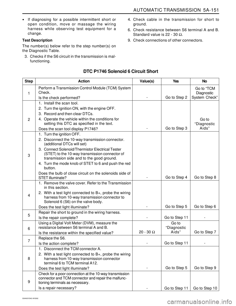
DTC P1746 Solenoid 6 Circuit Short
If diagnosing for a possible intermittent short or
open condition, move or massage the wiring
harness while observing test equipment for a
change.
Test Description
The number(s) below refer to the step number(s) on
the Diagnostic Table.
3. Checks if the S6 circuit in the transmission is mal-
functioning.4. Check cable in the transmission for short to
ground.
6. Check resistance between S6 terminal A and B.
Standard value is 22 - 30 Ω.
9. Check connections of other connectors.
- Go to Step 11 - 1Perform a Transmission Control Module (TCM) System
Check.
Is the check performed?
1. Install the scan tool.
2. Turn the ignition ON, with the engine OFF.
3. Record and then clear DTCs.
4. Operate the vehicle within the conditions for
setting this DTC as specified in the text.
Does the scan tool display P1746?
1. Turn the ignition OFF.
2. Disconnect the 10-way transmission connector.
(additional DTCs will set)
3. Connect Solenoid/Thermistor Electrical Tester
(STET) to the 10-way transmission connector of
transmission side and to the good ground.
4. Turn the mode knob of STET to 6 and push the red
button.
Does the bulb of close circuit on the solenoids side of
STET illuminate?
1. Remove the valve cover. Refer to the Transmission
in this section.
2. With a test light connected to B+, probe the wiring
harness from 10-way transmission connector to
Solenoid 6 (S6) on the valve body.
Does the test light illuminate?
Repair the short to ground in the wiring harness.
Is the repair complete?
Using a Digital Volt Meter (DVM), measure the
resistance between S6 terminal A and B.
Is the resistance within the specified value?
Replace the S6.
Is the action complete?
1. Disconnect the TCM connector A.
2. With a test light connected to B+, probe the wiring
harness from 10-way transmission connector
terminal 6 to TCM terminal A12.
Does the test light illuminate?
Check for a poor connection at the 10-way transmission
connector and TCM connector and repair the malfunc-
tioning terminals as necessary.
Is a repair necessary?
StepAction Value(s) Yes No
2
3
-
Go to Step 2 Go to “TCM
Diagnostic
System Check”
- Go to Step 4 Go to Step 8
5
6 4
- Go to Step 5 Go to Step 6
- Go to Step 11 -
7
8
9
- Go to Step 5 Go to Step 9
- Go to Step 11 Go to Step 10
- Go to Step 3Go to
“Diagnostic
Aids”
20 - 30 ΩGo to
“Diagnostic
Aids” Go to Step 7
Page 1253 of 2053
AUTOMATIC TRANSMISSION 5A-155
SSANGYONG MY2002
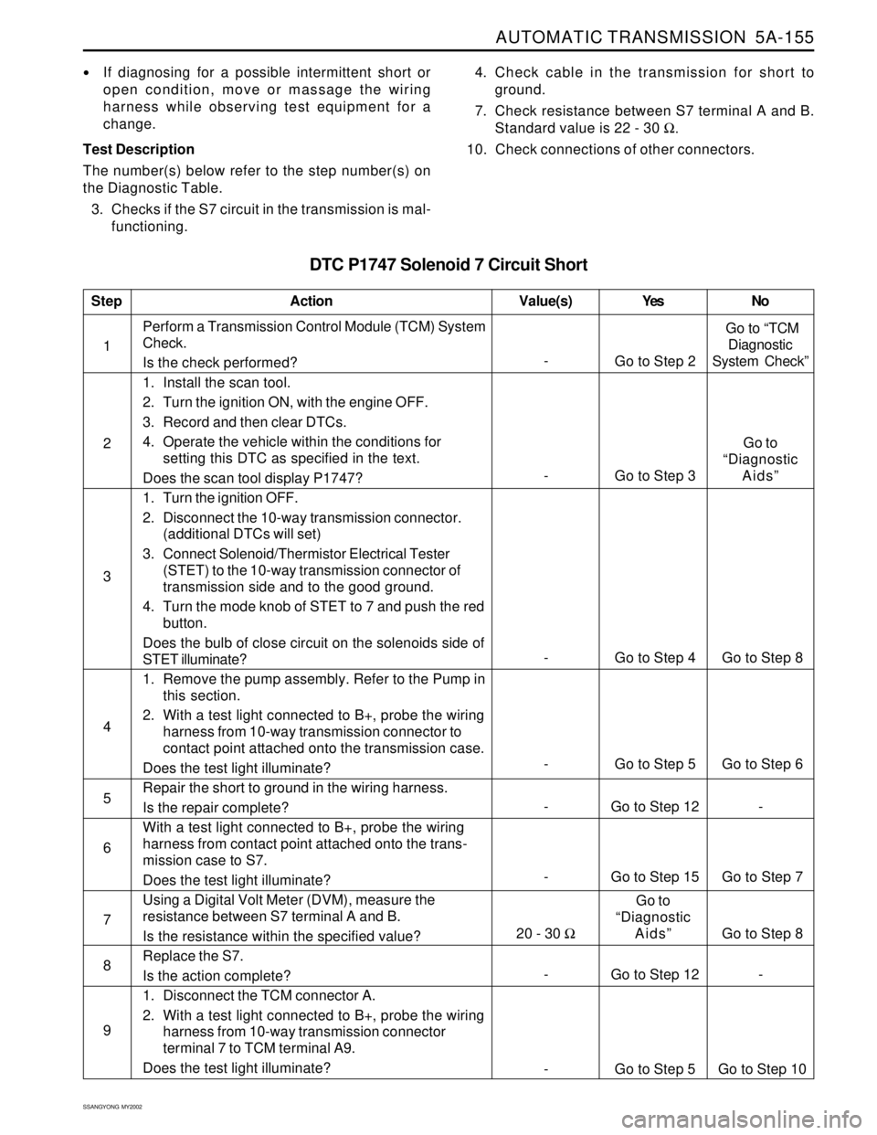
DTC P1747 Solenoid 7 Circuit Short
If diagnosing for a possible intermittent short or
open condition, move or massage the wiring
harness while observing test equipment for a
change.
Test Description
The number(s) below refer to the step number(s) on
the Diagnostic Table.
3. Checks if the S7 circuit in the transmission is mal-
functioning.4. Check cable in the transmission for short to
ground.
7. Check resistance between S7 terminal A and B.
Standard value is 22 - 30 Ω.
10. Check connections of other connectors.
- Go to Step 15 Go to Step 7 1Perform a Transmission Control Module (TCM) System
Check.
Is the check performed?
1. Install the scan tool.
2. Turn the ignition ON, with the engine OFF.
3. Record and then clear DTCs.
4. Operate the vehicle within the conditions for
setting this DTC as specified in the text.
Does the scan tool display P1747?
1. Turn the ignition OFF.
2. Disconnect the 10-way transmission connector.
(additional DTCs will set)
3. Connect Solenoid/Thermistor Electrical Tester
(STET) to the 10-way transmission connector of
transmission side and to the good ground.
4. Turn the mode knob of STET to 7 and push the red
button.
Does the bulb of close circuit on the solenoids side of
STET illuminate?
1. Remove the pump assembly. Refer to the Pump in
this section.
2. With a test light connected to B+, probe the wiring
harness from 10-way transmission connector to
contact point attached onto the transmission case.
Does the test light illuminate?
Repair the short to ground in the wiring harness.
Is the repair complete?
With a test light connected to B+, probe the wiring
harness from contact point attached onto the trans-
mission case to S7.
Does the test light illuminate?
Using a Digital Volt Meter (DVM), measure the
resistance between S7 terminal A and B.
Is the resistance within the specified value?
Replace the S7.
Is the action complete?
1. Disconnect the TCM connector A.
2. With a test light connected to B+, probe the wiring
harness from 10-way transmission connector
terminal 7 to TCM terminal A9.
Does the test light illuminate?
StepAction Value(s) Yes No
2
3
-
Go to Step 2 Go to “TCM
Diagnostic
System Check”
- Go to Step 4 Go to Step 8
5
6 4
- Go to Step 5 Go to Step 6
- Go to Step 12 -
7
8
9
- Go to Step 12 -
- Go to Step 5 Go to Step 10
- Go to Step 3Go to
“Diagnostic
Aids”
20 - 30 ΩGo to
“Diagnostic
Aids”
Go to Step 8
Page 1348 of 2053

SSANGYONG MY2002
5B-40 MANUAL TRANSMISSION
COUNTER SHAFT
Disassembly Procedure
1. Using a hydraulic press and special tool, remove
the front bearing assembly from the counter shaft.
2. Check and clean all removed parts and replace if
necessary.
YAD5B0J0
YAD5B0K0
YAD5B0M0
YAD5B0L0
Assembly Procedure
1. Using a hydraulic press and installer, press the
front bearing assembly onto the counter shaft.
2. Install is as follows :
Install a new O-ring on the counter shaft outer
race and lubricate it.
Using a installer, lightly tap the race into its
bore until the O-ring is compressed.
Install the race to be fully seated on the inside
of the case.
EXTENSION HOUSING
Disassembly Procedure
1. Remove the vent from the extension housing.
2. Remove the O-ring and steel ring from the rear of
the extension housing.
3. Check and clean all removed parts and replace if
necessary.
Assembly Procedure
1. Install the O-ring and steel ring to the rear of the
extension housing.
2. Install the vent to the extension housing.
Page 1408 of 2053
SSANGYONG MY2002
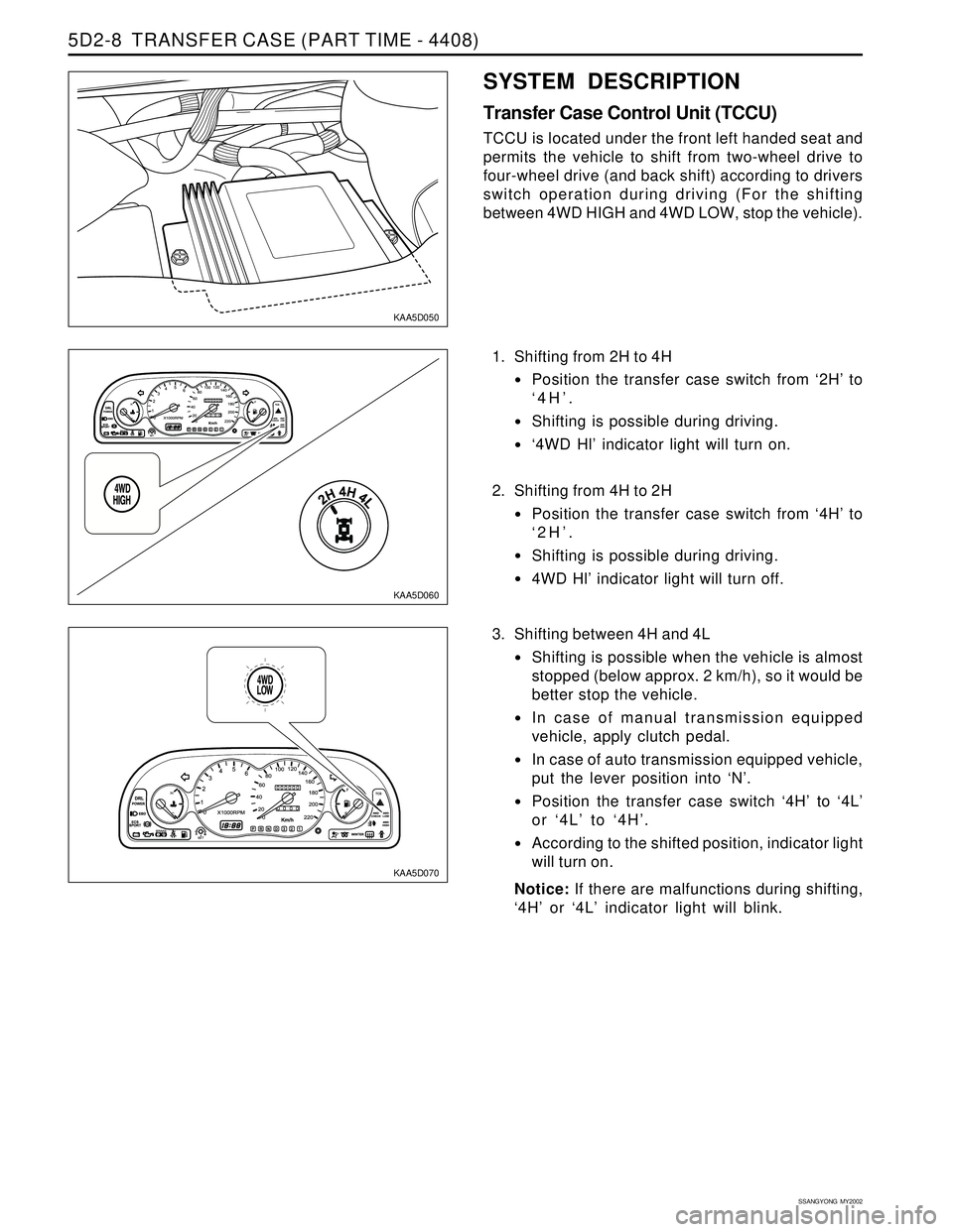
5D2-8 TRANSFER CASE (PART TIME - 4408)
KAA5D050
KAA5D060
KAA5D070
1. Shifting from 2H to 4H
Position the transfer case switch from ‘2H’ to
‘4H’.
Shifting is possible during driving.
‘4WD Hl’ indicator light will turn on.
2. Shifting from 4H to 2H
Position the transfer case switch from ‘4H’ to
‘2H’.
Shifting is possible during driving.
4WD Hl’ indicator light will turn off.
SYSTEM DESCRIPTION
Transfer Case Control Unit (TCCU)
TCCU is located under the front left handed seat and
permits the vehicle to shift from two-wheel drive to
four-wheel drive (and back shift) according to drivers
switch operation during driving (For the shifting
between 4WD HIGH and 4WD LOW, stop the vehicle).
3. Shifting between 4H and 4L
Shifting is possible when the vehicle is almost
stopped (below approx. 2 km/h), so it would be
better stop the vehicle.
In case of manual transmission equipped
vehicle, apply clutch pedal.
In case of auto transmission equipped vehicle,
put the lever position into ‘N’.
Position the transfer case switch ‘4H’ to ‘4L’
or ‘4L’ to ‘4H’.
According to the shifted position, indicator light
will turn on.
Notice: If there are malfunctions during shifting,
‘4H’ or ‘4L’ indicator light will blink.
Page 1411 of 2053
TRANSFER CASE (PART TIME - 4408) 5D2-11
SSANGYONG MY2002
KAA5D080
KAA5D090
KAA5D100
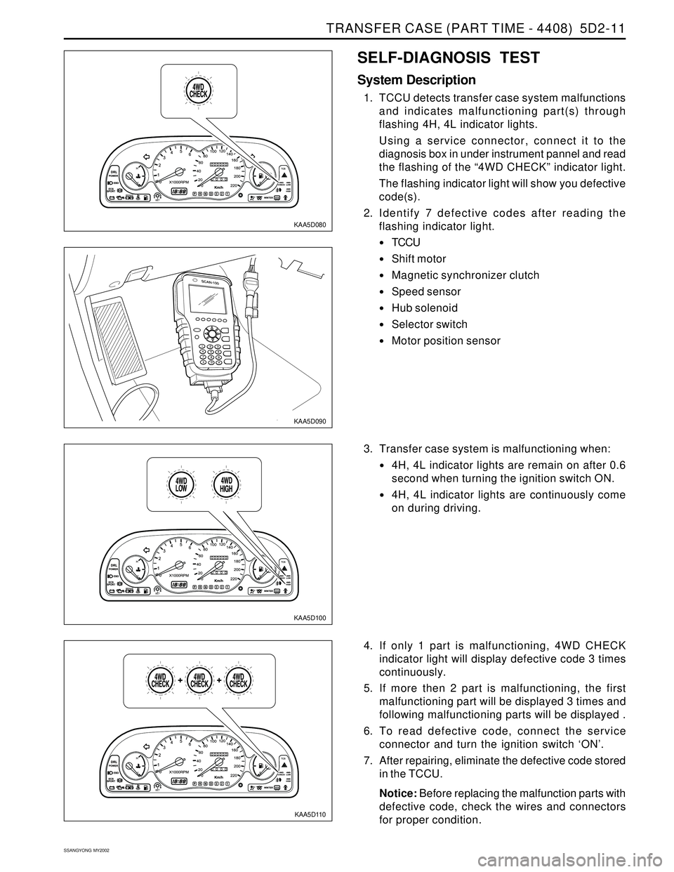
SELF-DIAGNOSIS TEST
System Description
1. TCCU detects transfer case system malfunctions
and indicates malfunctioning part(s) through
flashing 4H, 4L indicator lights.
Using a service connector, connect it to the
diagnosis box in under instrument pannel and read
the flashing of the “4WD CHECK” indicator light.
The flashing indicator light will show you defective
code(s).
2. Identify 7 defective codes after reading the
flashing indicator light.
TCCU
Shift motor
Magnetic synchronizer clutch
Speed sensor
Hub solenoid
Selector switch
Motor position sensor
KAA5D110
3. Transfer case system is malfunctioning when:
4H, 4L indicator lights are remain on after 0.6
second when turning the ignition switch ON.
4H, 4L indicator lights are continuously come
on during driving.
4. If only 1 part is malfunctioning, 4WD CHECK
indicator light will display defective code 3 times
continuously.
5. If more then 2 part is malfunctioning, the first
malfunctioning part will be displayed 3 times and
following malfunctioning parts will be displayed .
6. To read defective code, connect the service
connector and turn the ignition switch ‘ON’.
7. After repairing, eliminate the defective code stored
in the TCCU.
Notice: Before replacing the malfunction parts with
defective code, check the wires and connectors
for proper condition.
Page 1412 of 2053
SSANGYONG MY2002
5D2-12 TRANSFER CASE (PART TIME - 4408)
KAA5D120
KAA5D130
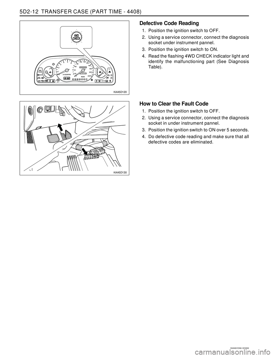
Defective Code Reading
1. Position the ignition switch to OFF.
2. Using a service connector, connect the diagnosis
socket under instrument pannel.
3. Position the ignition switch to ON.
4. Read the flashing 4WD CHECK indicator light and
identify the malfunctioning part (See Diagnosis
Table).
How to Clear the Fault Code
1. Position the ignition switch to OFF.
2. Using a service connector, connect the diagnosis
socket in under instrument pannel.
3. Position the ignition switch to ON over 5 seconds.
4. Do defective code reading and make sure that all
defective codes are eliminated.