Page 1413 of 2053
TRANSFER CASE (PART TIME - 4408) 5D2-13
SSANGYONG MY2002
Diagnostic Table
Connect a service connector. If turn the ignition switch
“ON” “4WD CHECK” indicator light will come on for
0.6 second and turn off for 3 seconds and then display
a defective code 3 times continuously.
4WD CHECK
Light
ON
OFF
4WD CHECK
Light
ON
OFF
4WD CHECK
Light
ON
OFF
4WD CHECK
Light
ON
OFF
4WD CHECK
Light
ON
OFFTCCU
Shift Motor
Synchronizer Clutch
Speed Sensor
Locking Hub Solenoid Defective Code No.
1
2
3
4
5
Malfunctioning Part
KAA5D140
KAA5D150
KAA5D160
KAA5D170
KAA5D180
Page 1414 of 2053
SSANGYONG MY2002
5D2-14 TRANSFER CASE (PART TIME - 4408)
4WD CHECK
Light
ON
OFF
4WD CHECK
Light
ON
OFFSelector Switch
Motor Position Sensor Defective Code No.
6
7
Malfunctioning Part
KAA5D190
KAA5D200
Page 1420 of 2053

TRANSFER CASE (PART TIME - 4408) 5D2-21
SSANGYONG MY2002
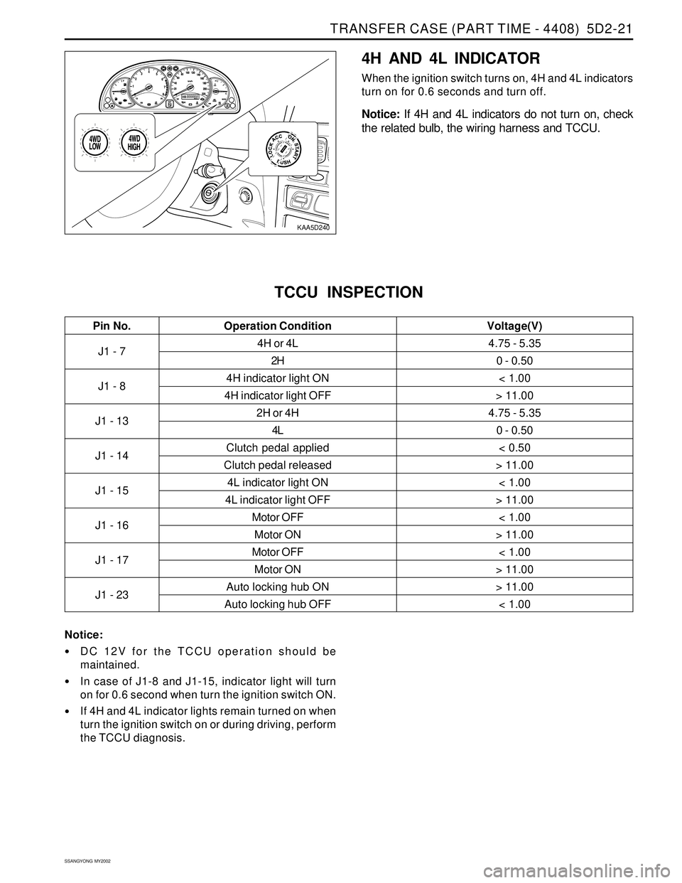
KAA5D240
4H AND 4L INDICATOR
When the ignition switch turns on, 4H and 4L indicators
turn on for 0.6 seconds and turn off.
Notice: If 4H and 4L indicators do not turn on, check
the related bulb, the wiring harness and TCCU.
J1 - 7
J1 - 8
J1 - 13
J1 - 14
J1 - 15
J1 - 16
J1 - 17
J1 - 234H or 4L
2H
4H indicator light ON
4H indicator light OFF
2H or 4H
4L
Clutch pedal applied
Clutch pedal released
4L indicator light ON
4L indicator light OFF
Motor OFF
Motor ON
Motor OFF
Motor ON
Auto locking hub ON
Auto locking hub OFF
TCCU INSPECTION
4.75 - 5.35
0 - 0.50
< 1.00
> 11.00
4.75 - 5.35
0 - 0.50
< 0.50
> 11.00
< 1.00
> 11.00
< 1.00
> 11.00
< 1.00
> 11.00
> 11.00
< 1.00
Pin No. Voltage(V)Operation Condition
Notice:
DC 12V for the TCCU operation should be
maintained.
In case of J1-8 and J1-15, indicator light will turn
on for 0.6 second when turn the ignition switch ON.
If 4H and 4L indicator lights remain turned on when
turn the ignition switch on or during driving, perform
the TCCU diagnosis.
Page 1438 of 2053

TRANSFER CASE (PART TIME - 4408) 5D2-39
SSANGYONG MY2002
KAA5D860
KAA5D870
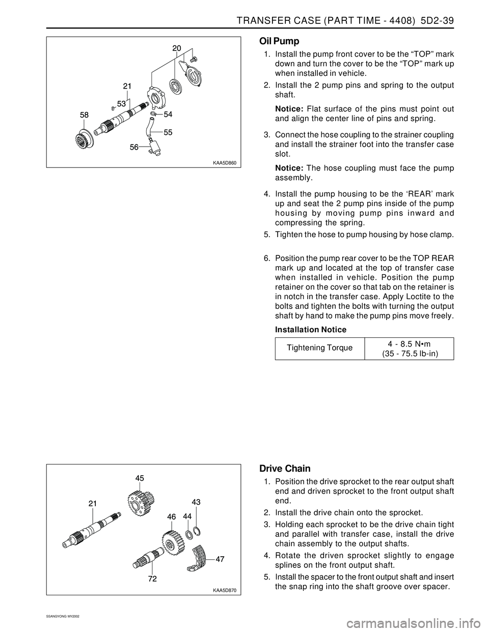
Oil Pump
1. Install the pump front cover to be the “TOP” mark
down and turn the cover to be the “TOP” mark up
when installed in vehicle.
2. Install the 2 pump pins and spring to the output
shaft.
Notice: Flat surface of the pins must point out
and align the center line of pins and spring.
3. Connect the hose coupling to the strainer coupling
and install the strainer foot into the transfer case
slot.
Notice: The hose coupling must face the pump
assembly.
4. Install the pump housing to be the ‘REAR’ mark
up and seat the 2 pump pins inside of the pump
housing by moving pump pins inward and
compressing the spring.
5. Tighten the hose to pump housing by hose clamp.
6. Position the pump rear cover to be the TOP REAR
mark up and located at the top of transfer case
when installed in vehicle. Position the pump
retainer on the cover so that tab on the retainer is
in notch in the transfer case. Apply Loctite to the
bolts and tighten the bolts with turning the output
shaft by hand to make the pump pins move freely.
Installation Notice
Tightening Torque4 - 8.5 Nm
(35 - 75.5 lb-in)
Drive Chain
1. Position the drive sprocket to the rear output shaft
end and driven sprocket to the front output shaft
end.
2. Install the drive chain onto the sprocket.
3. Holding each sprocket to be the drive chain tight
and parallel with transfer case, install the drive
chain assembly to the output shafts.
4. Rotate the driven sprocket slightly to engage
splines on the front output shaft.
5. Install the spacer to the front output shaft and insert
the snap ring into the shaft groove over spacer.
Page 1439 of 2053
SSANGYONG MY2002
5D2-40 TRANSFER CASE (PART TIME - 4408)
KAA5D880
KAA5D890
Lockup Shift
1. Install the lockup hub and return spring to the
lockup collar and insert the snap ring.
2. Install the rail shaft through reduction shift fork
assembly previously installed and into the blind
hole in case.
3. Engage the lockup fork into the 2WD/4WD groove
and check operation.
4. Install the shift collar hub to the output shaft spline.
5. Install the previously assembled electric shift cam
and assemble the clutch housing as follows.
Rotate the shift cam assembly to right so that
the end of the torsion spring contacts with
reduction shift fork side.
Holding the rail shaft, lift up the fork assembly
slightly.
Adjust electric shift cam assembly so that the
roller on reduction shift fork assembly is in
groove in shift cam and button on lockup fork
is on cam end.
Install the clutch housing over shift collar hub
and insert the retaining ring into the clutch collar
hub groove.
Page 1488 of 2053

SSANGYONG MY2002
6E-2 POWER STEERING AND COLUMN
GENERAL DESCRIPTION
Caution: To ensure the energy-absorbing action of
the steering column, it is important to use only the
specified screws, bolts, and nuts, tightened to the
specified torque.
In addition to the steering function, the steering column
provides safety and security.
The energy-absorbing column is designed to compress
in a front-end collision to lessen the chance of driver
injury.
The ignition switch and the lock are mounted on the
column, allowing the ignition and steering operations
to be locked to inhibit theft of the car.
The column levers trigger the turn signals, the headlight
beams, and the windshield washer and wipers.
A tilt steering column uses a spherical joint to allow
the steering wheel to tilt up and down. This enables
the driver to adjust the steering wheel to a comfortable
position.
Notice: Apply a thin coat of lithium grease to all friction
points when reassembling.
The column may be disassembled and reassembled
easily.
DESCRIPTION AND OPERATION
IGNITION SWITCH KEYHOLE LAMP
For description and lamp replacement information, Re-
fer to Section 9B, Lighting Systems.
IGNITION KEY REMINDER
The ignition key reminder alerts the driver that the key
is still in the ignition when the driver attempts to exit
the vehicle.
An internal switch in the ignition lock cylinder supplies
battery voltage to the reminder chime module when all
of the following conditions are true:
•The key is in the ignition switch.
The ignition is OFF.
The driver’s door is open.
For information on removal and installation of the re-
minder chime module, Refer to Section 9E, Instrumen-
tation/Driver Information.
Page 1490 of 2053
SSANGYONG MY2002
6E-4 POWER STEERING AND COLUMN
DIAGNOSTIC INFORMATION AND PROCEDURES
STEERING WHEEL FREEPLAY
INSPECTION
KAA6E020
Inspection Procedure
1. Start the engine and set the wheels in straight
ahead position.
2. Slightly move the steering wheel to the left and
right and measure steering wheel free play when
the front wheel is start to move.
Notice: If exceeds specification, the steering
column shaft connections and steering linkage
clearance. Replace or repair if necessary.
StandardMax. 30 mm
STEERING EFFORT INSPECTION
KAA6E030
Inspection Procedure
1. Place a vehicle on the paved flat ground with front
wheels in a straight ahead position.
2. Start the engine and run it at 1,000 rpm.
3. Using a scale, measure the steering effort in both
directions.
Notice : The difference in steering effort of left
and right should be within 0.6 kg.
StandardMax. 3.0 kg
Page 1493 of 2053

POWER STEERING AND COLUMN 6E-7
SSANGYONG MY2002
Check the turn signal/dimmer switch and turn signal/
dimmer switch lever for improper installation.
Check the signal/dimmer switch housing for foreign
material.ChecksActionRemove and inspect the turn signal/dimmer switch
and signal/dimmer switch lever. Reinstall the signal/
dimmer switch and signal/dimmer switch lever.
Remove any foreign material.
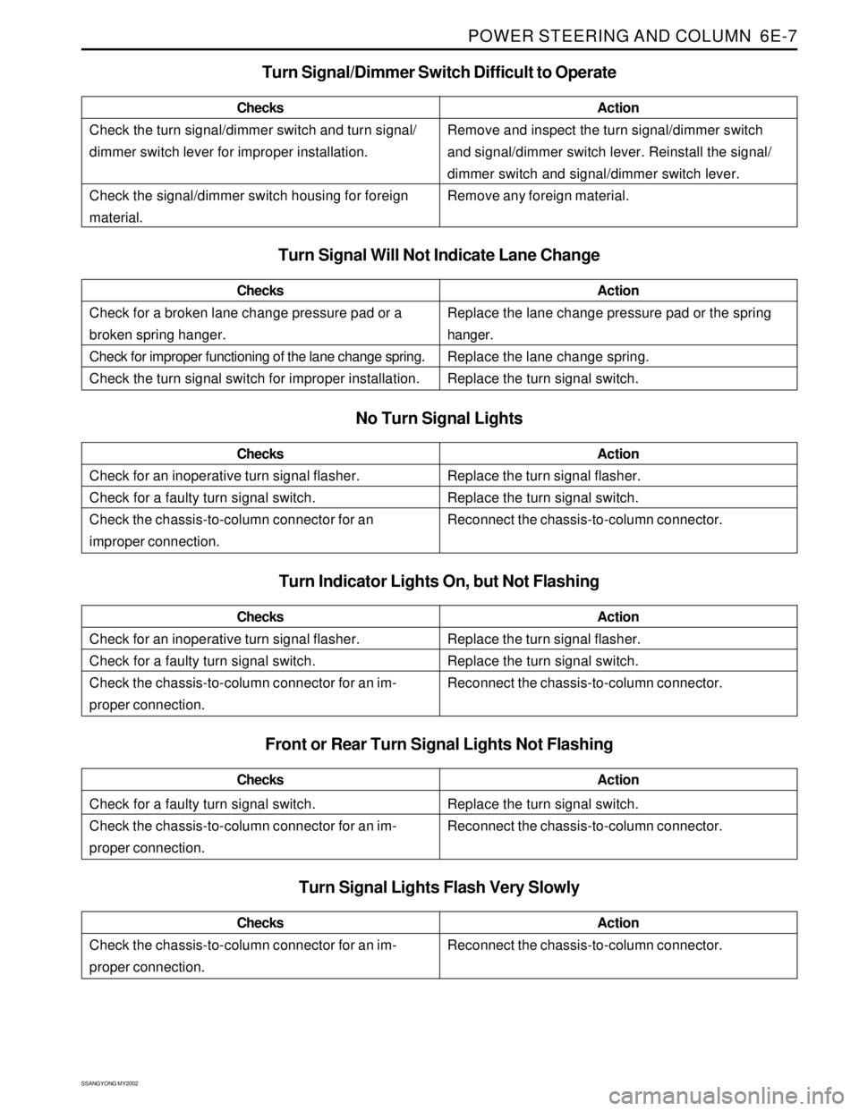
Turn Signal Will Not Indicate Lane Change
No Turn Signal Lights
Check for an inoperative turn signal flasher.
Check for a faulty turn signal switch.
Check the chassis-to-column connector for an
improper connection.ChecksActionReplace the turn signal flasher.
Replace the turn signal switch.
Reconnect the chassis-to-column connector.
Turn Signal/Dimmer Switch Difficult to Operate
Check for a broken lane change pressure pad or a
broken spring hanger.
Check for improper functioning of the lane change spring.
Check the turn signal switch for improper installation.ChecksActionReplace the lane change pressure pad or the spring
hanger.
Replace the lane change spring.
Replace the turn signal switch.
Turn Indicator Lights On, but Not Flashing
Check for a faulty turn signal switch.
Check the chassis-to-column connector for an im-
proper connection.ChecksActionReplace the turn signal switch.
Reconnect the chassis-to-column connector.
Front or Rear Turn Signal Lights Not Flashing
Turn Signal Lights Flash Very Slowly
Check the chassis-to-column connector for an im-
proper connection.ChecksActionReconnect the chassis-to-column connector.
Check for an inoperative turn signal flasher.
Check for a faulty turn signal switch.
Check the chassis-to-column connector for an im-
proper connection.ChecksActionReplace the turn signal flasher.
Replace the turn signal switch.
Reconnect the chassis-to-column connector.