1997 SSANGYONG KORANDO light
[x] Cancel search: lightPage 1502 of 2053
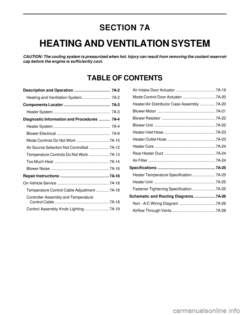
SECTION 7A
HEATING AND VENTILATION SYSTEM
CAUTION: The cooling system is pressurized when hot. Injury can result from removing the coolant reservoir
cap before the engine is sufficiently cool.
TABLE OF CONTENTS
Description and Operation ................................7A-2
Heating and Ventilation System .........................7A-2
Components Locator ..........................................7A-3
Heater System ...................................................7A-3
Diagnostic Information and Procedures ..........7A-4
Heater System ...................................................7A-4
Blower Electrical ................................................7A-8
Mode Controls Do Not Work .............................7A-10
Air Source Selection Not Controlled ..................7A-12
Temperature Controls Do Not Work ..................7A-13
Too Much Heat .................................................7A-14
Blower Noise ....................................................7A-16
Repair Instructions ............................................7A-18
On-Vehicle Service..............................................7A-18
Temperature Control Cable Adjustment ............7A-18
Controller Assembly and Temperature
Control Cable .................................................7A-18
Control Assembly Knob Lighting ......................7A-19Air Intake Door Actuator ...................................7A-19
Mode Control Door Actuator .............................7A-20
Heater/Air Distributor Case Assembly ..............7A-20
Blower Motor ....................................................7A-21
Blower Resistor ................................................7A-22
Blower Unit .......................................................7A-22
Heater Inlet Hose ..............................................7A-23
Heater Outlet Hose ...........................................7A-23
Heater Core......................................................7A-24
Rear Heater Duct ..............................................7A-24
Air Filter ............................................................7A-24
Specifications .................................................... 7A-25
Heater Temperature Specification .....................7A-25
Heater Unit .......................................................7A-25
Fastener Tightening Specification .....................7A-25
Schematic and Routing Diagrams ................... 7A-26
Non - A/C Wiring Diagram ................................7A-26
Airflow Through Vents .......................................7A-28
Page 1509 of 2053
SSANGYONG MY2002
7A-8 HEATING AND VENTILATION SYSTEM
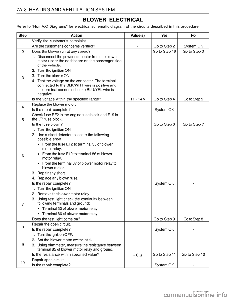
BLOWER ELECTRICAL
Refer to “Non A/C Diagrams” for electrical schematic diagram of the circuits described in this procedure.
Step
1
2
3
4
5
6
7
8
9
10
Action
Verify the customer’s complaint.
Are the customer’s concerns verified?
Does the blower run at any speed?
1. Disconnect the power connector from the blower
motor under the dashboard on the passenger side
of the vehicle.
2. Turn the ignition ON.
3. Turn the blower ON.
4. Test the voltage on the connector. The terminal
connected to the BLK/WHT wire is positive and
the terminal connected to the BLU/YEL wire is
negative.
Is the voltage within the specified range?
Replace the blower motor.
Is the repair complete?
Check fuse EF2 in the engine fuse block and F19 in
the I/P fuse block.
Is the fuse blown?
1. Turn the ignition ON.
2. Use a short detector to locate the following
possible short:
From the fuse EF2 to terminal 30 of blower
motor relay.
From the fuse F19 to terminal 86 of blower
motor relay.
From the terminal 87 of blower motor relay to
blower motor.
3. Repair any short.
4. Replace any blown fuse.
Is the repair complete?
1. Turn the ignition ON.
2. Remove the blower motor relay.
3. Using test light check the continuity between
following terminals and ground:
Terminal 30 of blower motor relay.
Terminal 86 of blower motor relay.
Does the test light come on?
Repair the open circuit.
Is the repair complete?
1. Turn the ignition OFF.
2. Set the blower motor switch at 4.
3. Using ohmmeter, measure the resistance between
terminal 85 of blower motor relay and ground.
Is the resistance within specified value?
Repair open circuit.
Is the repair complete?Yes
Go to Step 2
Go to Step 16
Go to Step 4
System OK
Go to Step 6
System OK
Go to Step 9
System OK
Go to Step 11
System OKNo
System OK
Go to Step 3
Go to Step 5
-
Go to Step 7
-
Go to Step 8
-
Go to Step 10
-
Value(s)
-
11 - 14 v
≈ 0 Ω
Page 1510 of 2053
HEATING AND VENTILATION SYSTEM 7A-9
SSANGYONG MY2002
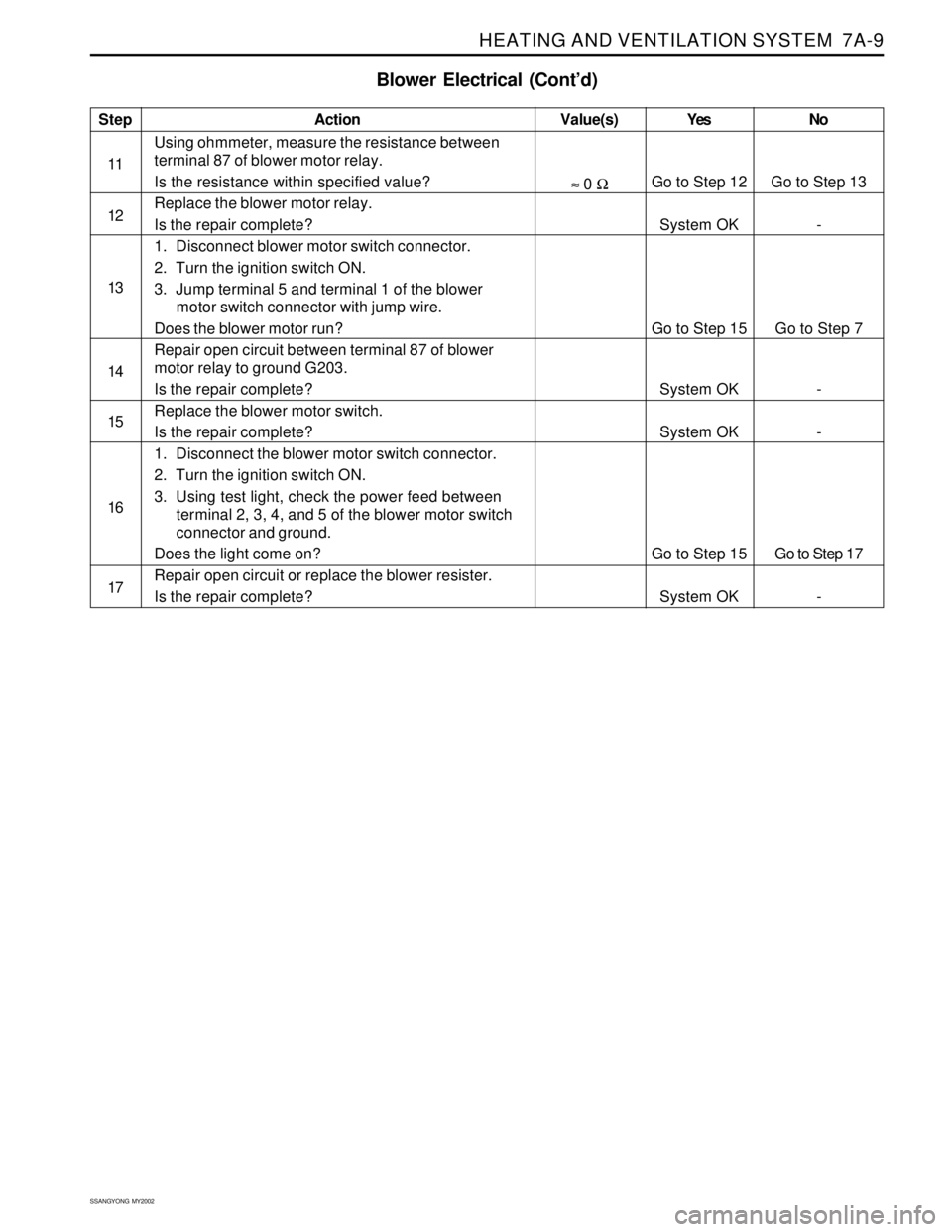
Blower Electrical (Cont’d)
Step
11
12
13
14
15
16
17Action
Using ohmmeter, measure the resistance between
terminal 87 of blower motor relay.
Is the resistance within specified value?
Replace the blower motor relay.
Is the repair complete?
1. Disconnect blower motor switch connector.
2. Turn the ignition switch ON.
3. Jump terminal 5 and terminal 1 of the blower
motor switch connector with jump wire.
Does the blower motor run?
Repair open circuit between terminal 87 of blower
motor relay to ground G203.
Is the repair complete?
Replace the blower motor switch.
Is the repair complete?
1. Disconnect the blower motor switch connector.
2. Turn the ignition switch ON.
3. Using test light, check the power feed between
terminal 2, 3, 4, and 5 of the blower motor switch
connector and ground.
Does the light come on?
Repair open circuit or replace the blower resister.
Is the repair complete?Yes
Go to Step 12
System OK
Go to Step 15
System OK
System OK
Go to Step 15
System OKNo
Go to Step 13
-
Go to Step 7
-
-
Go to Step 17
-Value(s)
≈ 0 Ω
Page 1520 of 2053
HEATING AND VENTILATION SYSTEM 7A-19
SSANGYONG MY2002
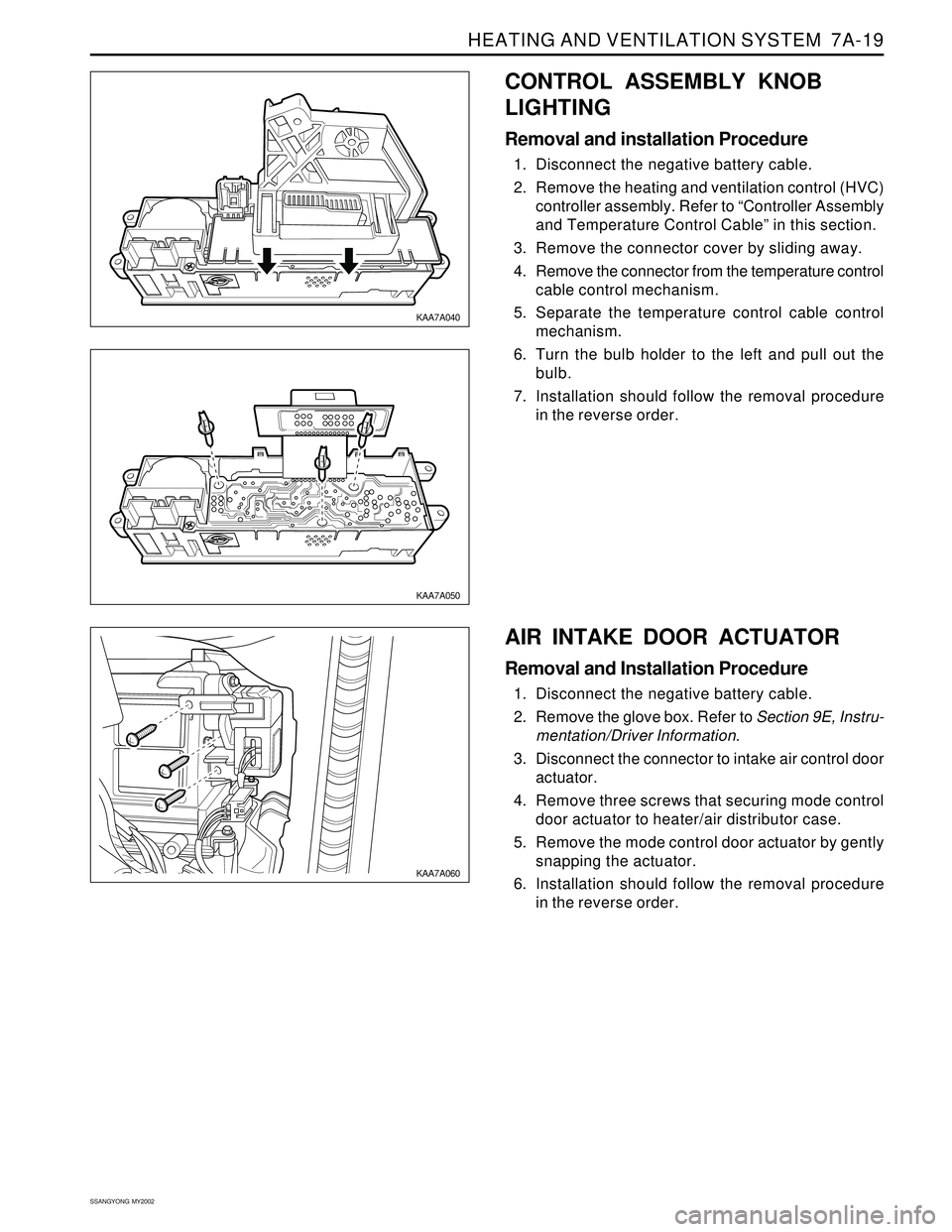
CONTROL ASSEMBLY KNOB
LIGHTING
Removal and installation Procedure
1. Disconnect the negative battery cable.
2. Remove the heating and ventilation control (HVC)
controller assembly. Refer to “Controller Assembly
and Temperature Control Cable” in this section.
3. Remove the connector cover by sliding away.
4. Remove the connector from the temperature control
cable control mechanism.
5. Separate the temperature control cable control
mechanism.
6. Turn the bulb holder to the left and pull out the
bulb.
7. Installation should follow the removal procedure
in the reverse order.
KAA7A040
KAA7A050
KAA7A060
AIR INTAKE DOOR ACTUATOR
Removal and Installation Procedure
1. Disconnect the negative battery cable.
2. Remove the glove box. Refer to Section 9E, Instru-
mentation/Driver Information.
3. Disconnect the connector to intake air control door
actuator.
4. Remove three screws that securing mode control
door actuator to heater/air distributor case.
5. Remove the mode control door actuator by gently
snapping the actuator.
6. Installation should follow the removal procedure
in the reverse order.
Page 1562 of 2053
SSANGYONG MY2002
7D-8 FATC-HAVC
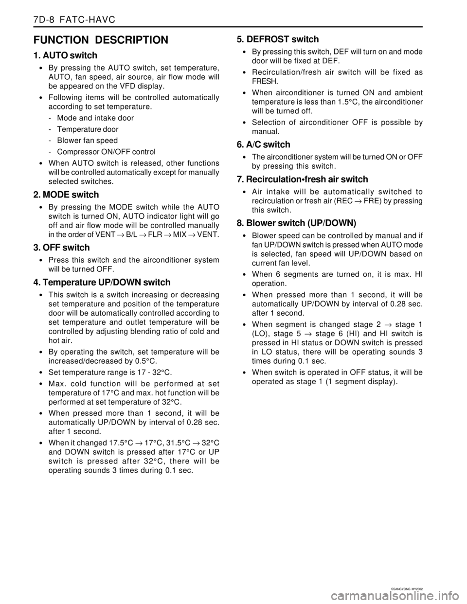
FUNCTION DESCRIPTION
1. AUTO switch
By pressing the AUTO switch, set temperature,
AUTO, fan speed, air source, air flow mode will
be appeared on the VFD display.
Following items will be controlled automatically
according to set temperature.
- Mode and intake door
- Temperature door
- Blower fan speed
- Compressor ON/OFF control
When AUTO switch is released, other functions
will be controlled automatically except for manually
selected switches.
2. MODE switch
By pressing the MODE switch while the AUTO
switch is turned ON, AUTO indicator light will go
off and air flow mode will be controlled manually
in the order of VENT → B/L → FLR → MIX → VENT.
3. OFF switch
Press this switch and the airconditioner system
will be turned OFF.
4. Temperature UP/DOWN switch
This switch is a switch increasing or decreasing
set temperature and position of the temperature
door will be automatically controlled according to
set temperature and outlet temperature will be
controlled by adjusting blending ratio of cold and
hot air.
By operating the switch, set temperature will be
increased/decreased by 0.5°C.
Set temperature range is 17 - 32°C.
Max. cold function will be performed at set
temperature of 17°C and max. hot function will be
performed at set temperature of 32°C.
When pressed more than 1 second, it will be
automatically UP/DOWN by interval of 0.28 sec.
after 1 second.
When it changed 17.5°C → 17°C, 31.5°C → 32°C
and DOWN switch is pressed after 17°C or UP
switch is pressed after 32°C, there will be
operating sounds 3 times during 0.1 sec.
5. DEFROST switch
By pressing this switch, DEF will turn on and mode
door will be fixed at DEF.
Recirculation/fresh air switch will be fixed as
FRESH.
When airconditioner is turned ON and ambient
temperature is less than 1.5°C, the airconditioner
will be turned off.
Selection of airconditioner OFF is possible by
manual.
6. A/C switch
The airconditioner system will be turned ON or OFF
by pressing this switch.
7. Recirculationfresh air switch
Air intake will be automatically switched to
recirculation or fresh air (REC → FRE) by pressing
this switch.
8. Blower switch (UP/DOWN)
Blower speed can be controlled by manual and if
fan UP/DOWN switch is pressed when AUTO mode
is selected, fan speed will UP/DOWN based on
current fan level.
When 6 segments are turned on, it is max. HI
operation.
When pressed more than 1 second, it will be
automatically UP/DOWN by interval of 0.28 sec.
after 1 second.
When segment is changed stage 2 → stage 1
(LO), stage 5 → stage 6 (HI) and HI switch is
pressed in HI status or DOWN switch is pressed
in LO status, there will be operating sounds 3
times during 0.1 sec.
When switch is operated in OFF status, it will be
operated as stage 1 (1 segment display).
Page 1574 of 2053
SSANGYONG MY2002
7D-20 FATC-HAVC
KAA7D270
KAA7D280
KAA7D290
KAA7D300
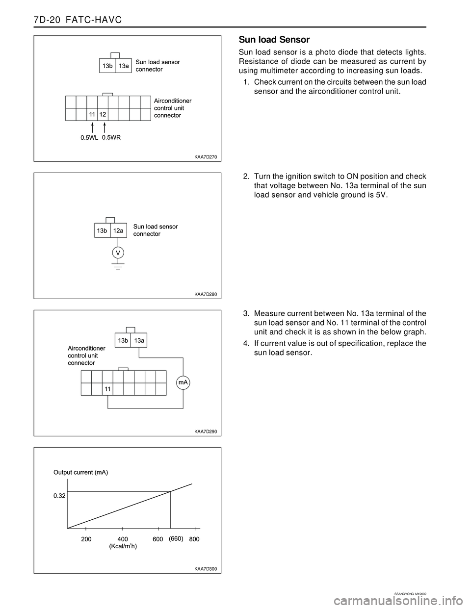
Sun load Sensor
Sun load sensor is a photo diode that detects lights.
Resistance of diode can be measured as current by
using multimeter according to increasing sun loads.
1. Check current on the circuits between the sun load
sensor and the airconditioner control unit.
2. Turn the ignition switch to ON position and check
that voltage between No. 13a terminal of the sun
load sensor and vehicle ground is 5V.
3. Measure current between No. 13a terminal of the
sun load sensor and No. 11 terminal of the control
unit and check it is as shown in the below graph.
4. If current value is out of specification, replace the
sun load sensor.
Page 1653 of 2053
SSANGYONG MY2002
9A-2 BODY WIRING SYSTEM
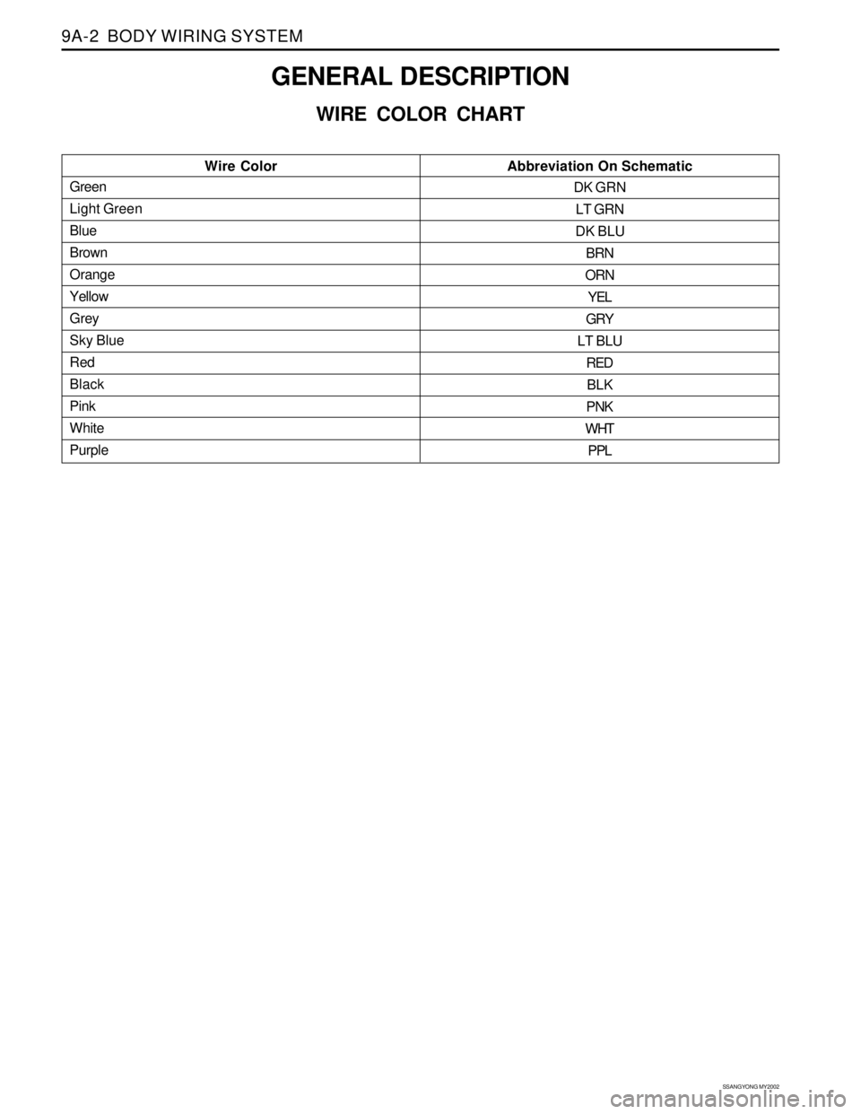
GENERAL DESCRIPTION
WIRE COLOR CHART
Green
Light Green
Blue
Brown
Orange
Yellow
Grey
Sky Blue
Red
Black
Pink
White
PurpleWire Color Abbreviation On SchematicDK GRN
LT GRN
DK BLU
BRN
ORN
YEL
GRY
LT BLU
RED
BLK
PNK
WHT
PPL
Page 1658 of 2053
BODY WIRING SYSTEM 9A-7
SSANGYONG MY2002
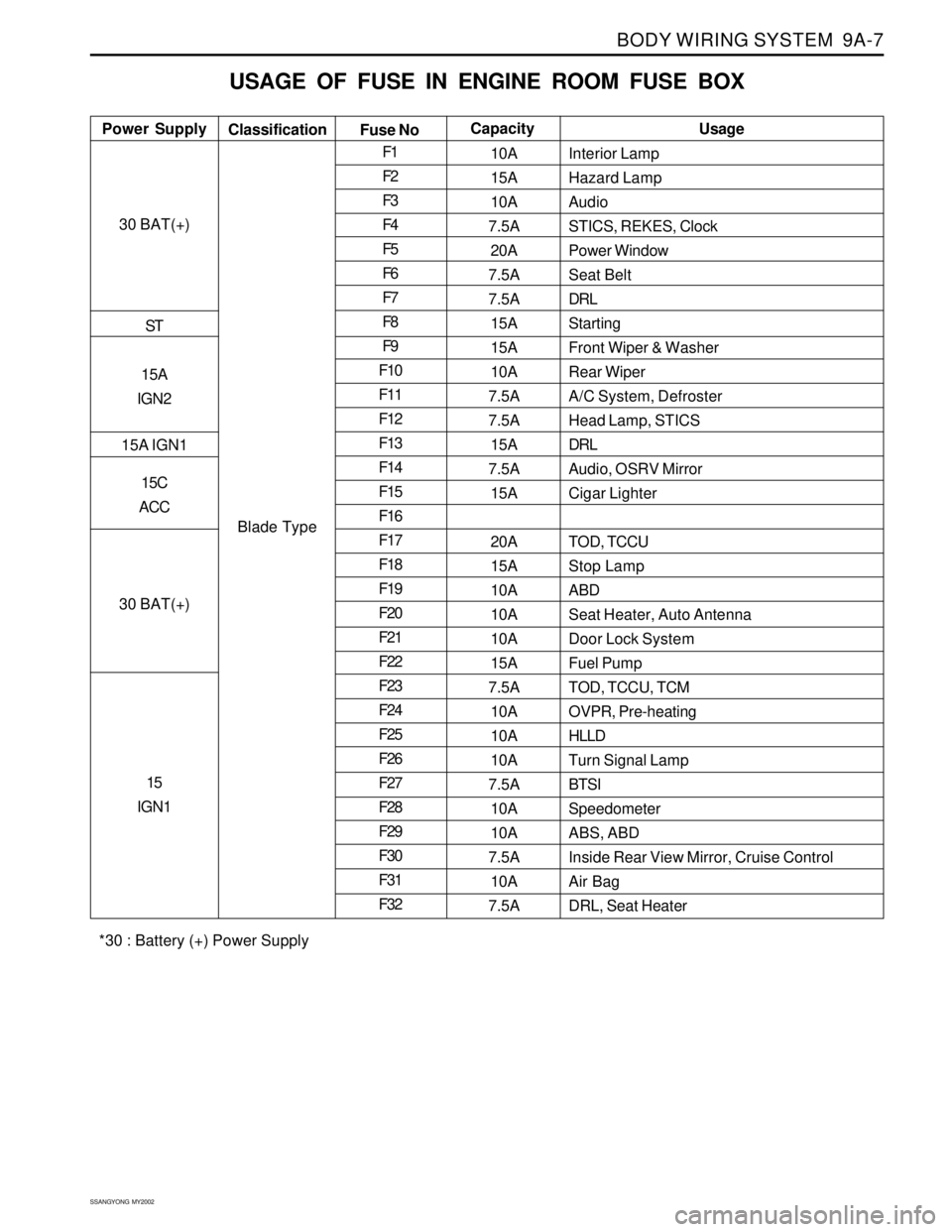
USAGE OF FUSE IN ENGINE ROOM FUSE BOX
Interior Lamp
Hazard Lamp
Audio
STICS, REKES, Clock
Power Window
Seat Belt
DRL
Starting
Front Wiper & Washer
Rear Wiper
A/C System, Defroster
Head Lamp, STICS
DRL
Audio, OSRV Mirror
Cigar Lighter
TOD, TCCU
Stop Lamp
ABD
Seat Heater, Auto Antenna
Door Lock System
Fuel Pump
TOD, TCCU, TCM
OVPR, Pre-heating
HLLD
Turn Signal Lamp
BTSI
Speedometer
ABS, ABD
Inside Rear View Mirror, Cruise Control
Air Bag
DRL, Seat Heater Power SupplyUsage
Classification
Fuse NoCapacity
30 BAT(+)
ST
15A
IGN2
15A IGN1
15C
ACC
30 BAT(+)
15
IGN1
Blade TypeF1
F2
F3
F4
F5
F6
F7
F8
F9
F10
F11
F12
F13
F14
F15
F16
F17
F18
F19
F20
F21
F22
F23
F24
F25
F26
F27
F28
F29
F30
F31
F3210A
15A
10A
7.5A
20A
7.5A
7.5A
15A
15A
10A
7.5A
7.5A
15A
7.5A
15A
20A
15A
10A
10A
10A
15A
7.5A
10A
10A
10A
7.5A
10A
10A
7.5A
10A
7.5A
*30 : Battery (+) Power Supply