1997 SSANGYONG KORANDO light
[x] Cancel search: lightPage 1107 of 2053
AUTOMATIC TRANSMISSION 5A-13
SSANGYONG MY2002
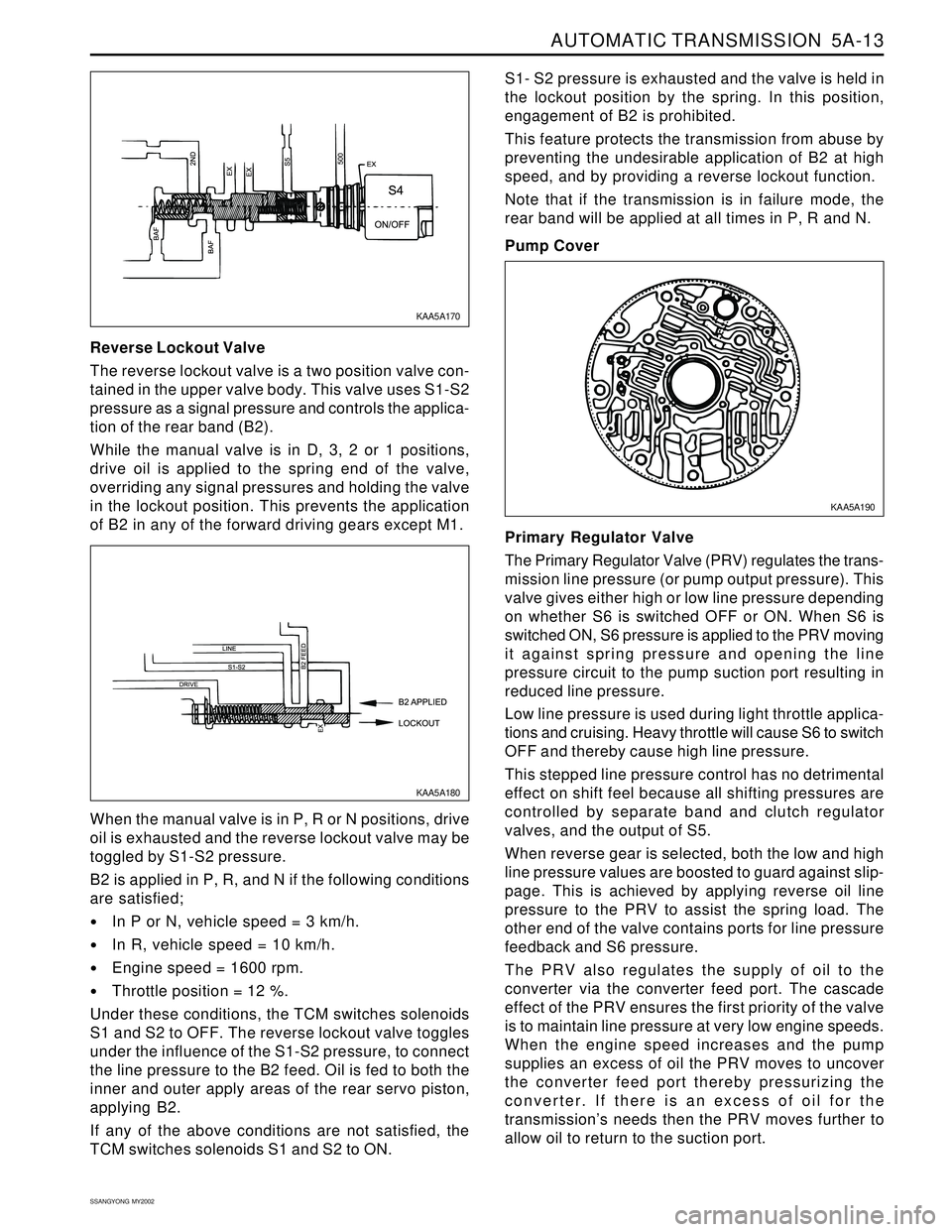
Reverse Lockout Valve
The reverse lockout valve is a two position valve con-
tained in the upper valve body. This valve uses S1-S2
pressure as a signal pressure and controls the applica-
tion of the rear band (B2).
While the manual valve is in D, 3, 2 or 1 positions,
drive oil is applied to the spring end of the valve,
overriding any signal pressures and holding the valve
in the lockout position. This prevents the application
of B2 in any of the forward driving gears except M1.S1- S2 pressure is exhausted and the valve is held in
the lockout position by the spring. In this position,
engagement of B2 is prohibited.
This feature protects the transmission from abuse by
preventing the undesirable application of B2 at high
speed, and by providing a reverse lockout function.
Note that if the transmission is in failure mode, the
rear band will be applied at all times in P, R and N.
Pump Cover
When the manual valve is in P, R or N positions, drive
oil is exhausted and the reverse lockout valve may be
toggled by S1-S2 pressure.
B2 is applied in P, R, and N if the following conditions
are satisfied;
In P or N, vehicle speed = 3 km/h.
In R, vehicle speed = 10 km/h.
Engine speed = 1600 rpm.
Throttle position = 12 %.
Under these conditions, the TCM switches solenoids
S1 and S2 to OFF. The reverse lockout valve toggles
under the influence of the S1-S2 pressure, to connect
the line pressure to the B2 feed. Oil is fed to both the
inner and outer apply areas of the rear servo piston,
applying B2.
If any of the above conditions are not satisfied, the
TCM switches solenoids S1 and S2 to ON.Primary Regulator Valve
The Primary Regulator Valve (PRV) regulates the trans-
mission line pressure (or pump output pressure). This
valve gives either high or low line pressure depending
on whether S6 is switched OFF or ON. When S6 is
switched ON, S6 pressure is applied to the PRV moving
it against spring pressure and opening the line
pressure circuit to the pump suction port resulting in
reduced line pressure.
Low line pressure is used during light throttle applica-
tions and cruising. Heavy throttle will cause S6 to switch
OFF and thereby cause high line pressure.
This stepped line pressure control has no detrimental
effect on shift feel because all shifting pressures are
controlled by separate band and clutch regulator
valves, and the output of S5.
When reverse gear is selected, both the low and high
line pressure values are boosted to guard against slip-
page. This is achieved by applying reverse oil line
pressure to the PRV to assist the spring load. The
other end of the valve contains ports for line pressure
feedback and S6 pressure.
The PRV also regulates the supply of oil to the
converter via the converter feed port. The cascade
effect of the PRV ensures the first priority of the valve
is to maintain line pressure at very low engine speeds.
When the engine speed increases and the pump
supplies an excess of oil the PRV moves to uncover
the converter feed port thereby pressurizing the
converter. If there is an excess of oil for the
transmission’s needs then the PRV moves further to
allow oil to return to the suction port.
KAA5A170
KAA5A180KAA5A190
Page 1133 of 2053
AUTOMATIC TRANSMISSION 5A-39
SSANGYONG MY2002
4. Place a fluid container below the fluid filler plug.
5. Clean all dirt from around the fluid filler plug.
Remove the fluid filler plug. Clean the filler plug
and check that there is no damage to the ‘O’ ring.
If fluid drains through the filler hole the transmis-
sion may have been overfilled. When the fluid
stops draining the fluid level is correct. Install
the fluid filler plug and tighten it to 33 Nm (24
lb-ft).
If fluid does not drain through the filler hole, the
transmission fluid level may be low. Install the
filler pump into the filler hole. Lower the vehicle
with the filler pump still connected and partially
fill the fluid through the filler hole.
Start the vehicle in P (Park) with the parking
brake and the brake applied. With the engine
idling, move the gear shift. control lever through
the gear ranges, pausing a few seconds in each
range and adding the fluid until gear application
is felt.
Return the gear shift lever to P (Park).
Turn the engine OFF and raise the vehicle. When
the three minutes passed after the engine
stopped, remove the filler pump.
Check if the fluid level is aligned with the bottom
of the filler hole. If not, add a small quantity of
fluid to the correct level. Install the fluid filler
plug and tighten it to 33 Nm (24 lb-ft).
If fluid does not drain through the filler hole al-
though adding a total of 1.5 liters, the transmission
should be inspected for fluid leaks and any leaks
should be fixed before setting the transmission
fluid level.
6. When the fluid level checking procedure is com-
pleted, wipe any fluid around the filler plug with a
rag or shop towel.
Fluid Level Set After Service
1. Depending on the service procedure performed,
add the following amounts of fluid through the filler
plug hole prior to adjusting the fluid level:
Converter empty 8.0 liters (8.5 quarts)
Converter full 3.8 liters (4.0 quarts)
2. Follow steps 1 through 4 of the Fluid Level Diagnosis
Procedure.
3. Clean all dirt from around the fluid filler plug.
Remove the fluid filler plug. Clean the filler plug
and check that there is no damage to the ‘O’ ring.
4. Lower the vehicle with the filler pump still connected
and start the vehicle in P (Park) with the parking
brake and the brake applied. With the engine idling,
move the gear shift control lever through the gear
ranges, pausing a few seconds in each range and
adding the fluid until gear application is felt.Then add an additional 0.5 litres of fluid. Return
the gear shift lever to P (Park). Turn the engine OFF
and raise the vehicle. Install the fluid filler plug and
tighten it to 33 Nm (24 lb-ft).
5. Drive the vehicle at 3.5 to 4.5 kilometers with light
throttle so that the engine does not exceed 2500
rpm.
This should result in the transmission temperature
being in the range 50 - 60 °C (82 - 140 °F). With the
brake applied, move the shift lever through the gear
ranges, pausing a few seconds in each range at
the engine idling.
6. Return the gear shift lever to P (Park).
Turn the en-gine OFF and raise the vehicle on the
hoist, if applicable, ensuring the vehicle is level.
When the three minutes passed after the engine
stopped, remove the filler plug.
Check if the fluid level is aligned with the bottom of
the filler hole. If not, add a small quantity of fluid to
the correct level. Install the fluid filler plug and
tighten it to 33 Nm (24 lb-ft).
7. Wipe any fluid around the filler plug with a rag or
shop towel.
FLUID LEAK DIAGNOSIS AND
REPAIR
The cause of most external leaks can generally be lo-
cated and repaired with the transmission in the vehicle.
Methods for Locating Leaks
General Method
1. Verify that the leak is transmission fluid.
2. Thoroughly clean the suspected leak area.
3. Drive the vehicle for approximately 25 km (15 miles)
or until the transmission reaches normal operating
temperature (88 °C, 190 °F).
4. Park the vehicle over clean paper or cardboard.
5. Turn the engine OFF and look for fluid spots on the
paper.
6. Make the necessary repairs to correct the leak.
Powder Method
1. Thoroughly clean the suspected leak area.
2. Apply an aerosol type powder (foot powder) to the
suspected leak area.
3. Drive the vehicle for approximately 25 km (15 miles)
or until the transmission reaches normal operating
temperature (88 °C, 190 °F).
4. Turn the engine OFF.
5. Inspect the suspected leak area and trace the leak
path through the powder to find the source of the
leak.
6. Make the necessary repairs.
Page 1134 of 2053
5A-40 AUTOMATIC TRANSMISSION
SSANGYONG MY2002
Dye and Black Light Method
1. Add dye to the transmission through the transmission
fluid filler plug. Follow the manufacturer’s recommen-
dation for the amount of dye to be used.
2. Use the black light to find the fluid leak.
3. Make the necessary repairs.
Repairing the Fluid Leak
Once the leak point is found the source of the leak
must be determined. The following list describes the
potential causes for the leak:
Fasteners are not torqued to specification.
Fastener threads and fastener holes are dirty or
corroded.
Gaskets, seals or sleeves are misaligned, damaged
or worn.
Damaged, warped or scratched seal bore or gasket
surface.
Loose or worn bearing causing excess seal or sleeve
wear.
Case or component porosity.
Fluid level is too high.
Plugged vent or damaged vent tube.
Water or coolant in fluid.
Fluid drain back holes plugged.
ELECTRICAL / GARAGE SHIFT
TEST
This preliminary test should be performed before a hoist
or road test to make sure electronic control inputs are
connected and operating. If the inputs are not checked
before operating the transmission, a simple electrical
condition could be misdiagnosed as a major
transmission condition.
A scan tool provides valuable information and must
be used on the automatic transmission for accurate
diagnosis.
1. Move gear shift control lever to P (Park) and set
the parking brake.
2. Connect scan tool to Data Link Connector (DLC)
terminal.
3. Start engine.
4. Turn the scan tool ON.
5. Verify that the appropriate signals are present.
These signals may include:
ENGINE SPEED
VEHICLE SPEED
THROTTLE POSITION
ACCEL. PEDAL POSITION
TRANSMISSION GEAR STATE
GEAR SHIFT LEVER POSITION
TRANSMISSION FLUID TEMPERATURE
CLOSED THROTTLE POSITION LEARN
OPEN THROTTLE POSITION LEARNT
CLOSED ACCEL. PEDAL POSITION LEARNT
OPEN ACCEL. PEDAL POSITION LEARNT
A/C COMPRESSOR STATUS
KICKDOWN SWITCH STATUS
4WD STATUS
MODE SWITCH
THROTTLE POSITION VOLTAGE
GEAR SHIFT LEVER POSITION VOLTAGE
TRANS. FLUID TEMPERATURE VOLTAGE
A/C SWITCH
KICKDOWN SWITCH VOLTAGE
4WD LAMP LOW VOLTAGE
4WD LAMP HIGH VOLTAGE
MODE SWITCH VOLTAGE
BATTERY VOLTAGE
6. Monitor the A/C COMPRESSOR STATUS signal
while pushing the A/C switch.
The A/C COMPRESSOR STATUS should come
ON when the A/C switch is pressed, and turn
OFF when the A/C switch is repushed.
7. Monitor the GEAR SHIFT LEVER POSITION signal
and move the gear shift control lever through all
the ranges.
Verify that the GEAR SHIFT LEVER POSITION
value matches the gear range indicated on the
instrument panel or console.
Gear selections should be immediate and not
harsh.
8. Move gear shift control lever to neutral and monitor
the THROTTLE POSITION signal while increasing
and decreasing engine speed with the accelerator
pedal.
THROTTLE POSITION should increase with en-
gine speed.
ROAD TEST PROCEDURE
Perform the road test using a scan tool.
This test should be performed when traffic and road
conditions permit.
Observe all traffic regulations.
ELECTRONIC ADJUSTMENTS
Idle Speed Adjustments
Carry out the adjustments to the idle speed as detailed
in the workshop manual.
Vehicle Coding
The vehicle coding is integrated as part of the
diagnostic software. A scan tool has the function to
code the ve-hicle through the K-line.
Page 1135 of 2053
5A-40 AUTOMATIC TRANSMISSION
SSANGYONG MY2002
Dye and Black Light Method
1. Add dye to the transmission through the transmission
fluid filler plug. Follow the manufacturer’s recommen-
dation for the amount of dye to be used.
2. Use the black light to find the fluid leak.
3. Make the necessary repairs.
Repairing the Fluid Leak
Once the leak point is found the source of the leak
must be determined. The following list describes the
potential causes for the leak:
Fasteners are not torqued to specification.
Fastener threads and fastener holes are dirty or
corroded.
Gaskets, seals or sleeves are misaligned, damaged
or worn.
Damaged, warped or scratched seal bore or gasket
surface.
Loose or worn bearing causing excess seal or sleeve
wear.
Case or component porosity.
Fluid level is too high.
Plugged vent or damaged vent tube.
Water or coolant in fluid.
Fluid drain back holes plugged.
ELECTRICAL / GARAGE SHIFT
TEST
This preliminary test should be performed before a hoist
or road test to make sure electronic control inputs are
connected and operating. If the inputs are not checked
before operating the transmission, a simple electrical
condition could be misdiagnosed as a major
transmission condition.
A scan tool provides valuable information and must
be used on the automatic transmission for accurate
diagnosis.
1. Move gear shift control lever to P (Park) and set
the parking brake.
2. Connect scan tool to Data Link Connector (DLC)
terminal.
3. Start engine.
4. Turn the scan tool ON.
5. Verify that the appropriate signals are present.
These signals may include:
ENGINE SPEED
VEHICLE SPEED
THROTTLE POSITION
ACCEL. PEDAL POSITION
TRANSMISSION GEAR STATE
GEAR SHIFT LEVER POSITION
TRANSMISSION FLUID TEMPERATURE
CLOSED THROTTLE POSITION LEARN
OPEN THROTTLE POSITION LEARNT
CLOSED ACCEL. PEDAL POSITION LEARNT
OPEN ACCEL. PEDAL POSITION LEARNT
A/C COMPRESSOR STATUS
KICKDOWN SWITCH STATUS
4WD STATUS
MODE SWITCH
THROTTLE POSITION VOLTAGE
GEAR SHIFT LEVER POSITION VOLTAGE
TRANS. FLUID TEMPERATURE VOLTAGE
A/C SWITCH
KICKDOWN SWITCH VOLTAGE
4WD LAMP LOW VOLTAGE
4WD LAMP HIGH VOLTAGE
MODE SWITCH VOLTAGE
BATTERY VOLTAGE
6. Monitor the A/C COMPRESSOR STATUS signal
while pushing the A/C switch.
The A/C COMPRESSOR STATUS should come
ON when the A/C switch is pressed, and turn
OFF when the A/C switch is repushed.
7. Monitor the GEAR SHIFT LEVER POSITION signal
and move the gear shift control lever through all
the ranges.
Verify that the GEAR SHIFT LEVER POSITION
value matches the gear range indicated on the
instrument panel or console.
Gear selections should be immediate and not
harsh.
8. Move gear shift control lever to neutral and monitor
the THROTTLE POSITION signal while increasing
and decreasing engine speed with the accelerator
pedal.
THROTTLE POSITION should increase with en-
gine speed.
ROAD TEST PROCEDURE
Perform the road test using a scan tool.
This test should be performed when traffic and road
conditions permit.
Observe all traffic regulations.
ELECTRONIC ADJUSTMENTS
Idle Speed Adjustments
Carry out the adjustments to the idle speed as detailed
in the workshop manual.
Vehicle Coding
The vehicle coding is integrated as part of the
diagnostic software. A scan tool has the function to
code the ve-hicle through the K-line.
Page 1142 of 2053
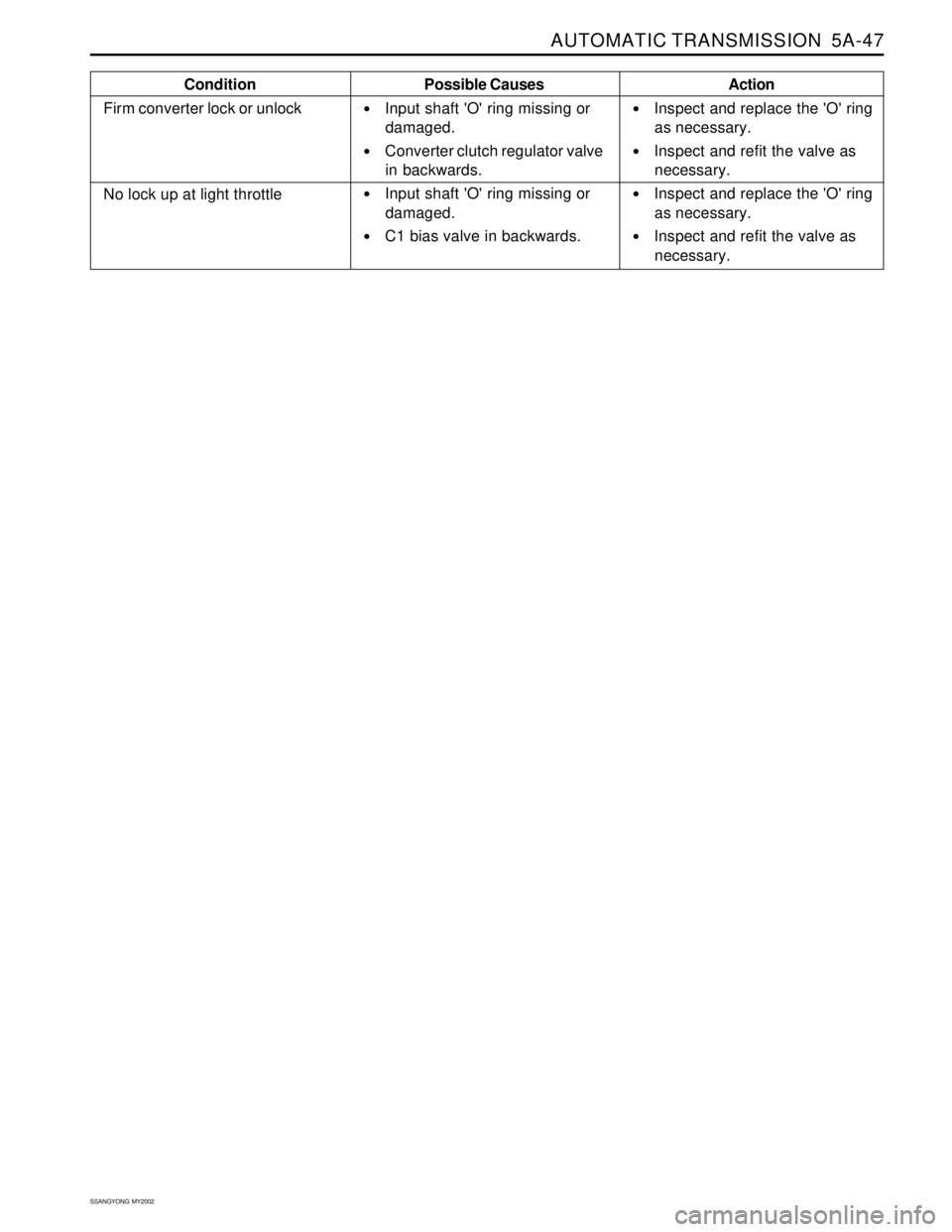
AUTOMATIC TRANSMISSION 5A-47
SSANGYONG MY2002
Condition
Firm converter lock or unlockPossible Causes
Input shaft 'O' ring missing or
damaged.
Converter clutch regulator valve
in backwards.
Input shaft 'O' ring missing or
damaged.
C1 bias valve in backwards.Action
Inspect and replace the 'O' ring
as necessary.
Inspect and refit the valve as
necessary.
Inspect and replace the 'O' ring
as necessary.
Inspect and refit the valve as
necessary.
No lock up at light throttle
Page 1152 of 2053
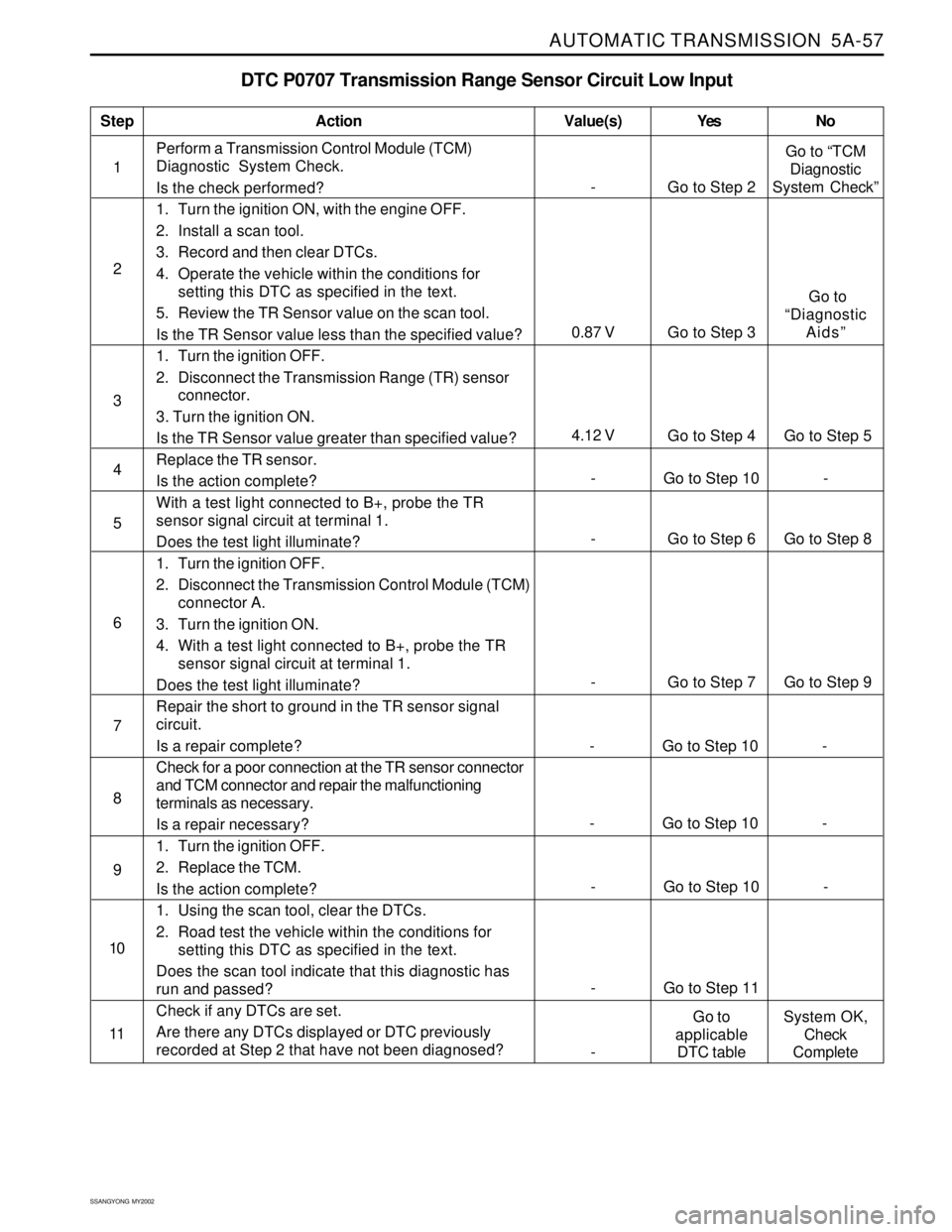
AUTOMATIC TRANSMISSION 5A-57
SSANGYONG MY2002
DTC P0707 Transmission Range Sensor Circuit Low Input
1Perform a Transmission Control Module (TCM)
Diagnostic System Check.
Is the check performed?
1. Turn the ignition ON, with the engine OFF.
2. Install a scan tool.
3. Record and then clear DTCs.
4. Operate the vehicle within the conditions for
setting this DTC as specified in the text.
5. Review the TR Sensor value on the scan tool.
Is the TR Sensor value less than the specified value?
1. Turn the ignition OFF.
2. Disconnect the Transmission Range (TR) sensor
connector.
3. Turn the ignition ON.
Is the TR Sensor value greater than specified value?
Replace the TR sensor.
Is the action complete?
With a test light connected to B+, probe the TR
sensor signal circuit at terminal 1.
Does the test light illuminate?
1. Turn the ignition OFF.
2. Disconnect the Transmission Control Module (TCM)
connector A.
3. Turn the ignition ON.
4. With a test light connected to B+, probe the TR
sensor signal circuit at terminal 1.
Does the test light illuminate?
Repair the short to ground in the TR sensor signal
circuit.
Is a repair complete?
Check for a poor connection at the TR sensor connector
and TCM connector and repair the malfunctioning
terminals as necessary.
Is a repair necessary?
1. Turn the ignition OFF.
2. Replace the TCM.
Is the action complete?
1. Using the scan tool, clear the DTCs.
2. Road test the vehicle within the conditions for
setting this DTC as specified in the text.
Does the scan tool indicate that this diagnostic has
run and passed?
Check if any DTCs are set.
Are there any DTCs displayed or DTC previously
recorded at Step 2 that have not been diagnosed?
StepAction Value(s) Yes No
2
3
- Go to Step 6 Go to Step 8 5
- Go to Step 7 Go to Step 9 6
- Go to Step 10 - 4
7
- Go to Step 10 - 8
- Go to Step 10 - 9
- Go to Step 11 10
11
- Go to Step 2Go to “TCM
Diagnostic
System Check”
4.12 V
Go to Step 4 Go to Step 5
0.87 V Go to Step 3 Go to
“Diagnostic
Aids”
-Go to
applicable
DTC tableSystem OK,
Check
Complete
- Go to Step 10 -
Page 1154 of 2053
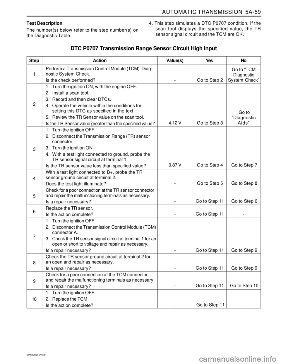
AUTOMATIC TRANSMISSION 5A-59
SSANGYONG MY2002
Test Description
The number(s) below refer to the step number(s) on
the Diagnostic Table.4. This step simulates a DTC P0707 condition. If the
scan tool displays the specified value, the TR
sensor signal circuit and the TCM are OK.
DTC P0707 Transmission Range Sensor Circuit High Input
1Perform a Transmission Control Module (TCM) Diag-
nostic System Check.
Is the check performed?
1. Turn the ignition ON, with the engine OFF.
2. Install a scan tool.
3. Record and then clear DTCs.
4. Operate the vehicle within the conditions for
setting this DTC as specified in the text.
5. Review the TR Sensor value on the scan tool.
Is the TR Sensor value greater than the specified value?
1. Turn the ignition OFF.
2. Disconnect the Transmission Range (TR) sensor
connector.
3. Turn the ignition ON.
4. With a test light connected to ground, probe the
TR sensor signal circuit at terminal 1.
Is the TR sensor value less than specified value?
With a test light connected to B+, probe the TR
sensor ground circuit at terminal 2.
Does the test light illuminate?
Check for a poor connection at the TR sensor connector
and repair the malfunctioning terminals as necessary.
Is a repair necessary?
Replace the TR sensor.
Is the action complete?
1. Turn the ignition OFF.
2. Disconnect the Transmission Control Module (TCM)
connector A.
3. Check the TR sensor signal circuit at terminal 1 for an
open or short to voltage and repair as necessary.
Is a repair necessary?
Check the TR sensor ground circuit at terminal 2 for
an open and repair as necessary.
Is a repair necessary?
Check for a poor connection at the TCM connector
and repair the malfunctioning terminals as necessary.
Is a repair necessary?
1. Turn the ignition OFF.
2. Replace the TCM.
Is the action complete?
StepAction Value(s) Yes No
2
3
- Go to Step 11 Go to Step 6 5
- Go to Step 11 - 6
- Go to Step 5 Go to Step 8 4
- Go to Step 11 Go to Step 9 7
- Go to Step 11 Go to Step 9 8
- Go to Step 11 Go to Step 10 9
10
- Go to Step 2Go to “TCM
Diagnostic
System Check”
0.87 V Go to Step 4 Go to Step 7
4.12 V Go to Step 3 Go to
“Diagnostic
Aids”
- Go to Step 11 -
Page 1158 of 2053
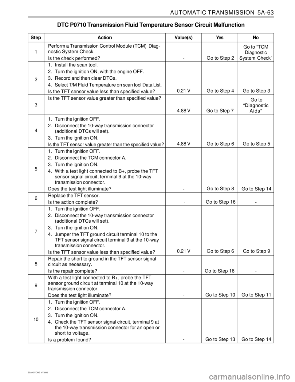
AUTOMATIC TRANSMISSION 5A-63
SSANGYONG MY2002
DTC P0710 Transmission Fluid Temperature Sensor Circuit Malfunction
1Perform a Transmission Control Module (TCM) Diag-
nostic System Check.
Is the check performed?
1. Install the scan tool.
2. Turn the ignition ON, with the engine OFF.
3. Record and then clear DTCs.
4. Select T/M Fluid Temperature on scan tool Data List.
Is the TFT sensor value less than specified value?
Is the TFT sensor value greater than specified value?
1. Turn the ignition OFF.
2. Disconnect the 10-way transmission connector
(additional DTCs will set).
3. Turn the ignition ON.
Is the TFT sensor value greater than the specified value?
1. Turn the ignition OFF.
2. Disconnect the TCM connector A.
3. Turn the ignition ON.
4. With a test light connected to B+, probe the TFT
sensor signal circuit, terminal 9 at the 10-way
transmission connector.
Does the test light illuminate?
Replace the TFT sensor.
Is the action complete?
1. Turn the ignition OFF.
2. Disconnect the 10-way transmission connector
(additional DTCs will set).
3. Turn the ignition ON.
4. Jumper the TFT ground circuit terminal 10 to the
TFT sensor signal circuit terminal 9 at the 10-way
transmission connector.
Is the TFT sensor value less than specified value?
Repair the short to ground in the TFT sensor signal
circuit as necessary.
Is the repair complete?
With a test light connected to B+, probe the TFT
sensor ground circuit at terminal 10 at the 10-way
transmission connector.
Does the test light illuminate?
1. Turn the ignition OFF.
2. Disconnect the TCM connector A.
3. Turn the ignition ON.
4. Check the TFT sensor signal circuit, terminal 9 at
the 10-way transmission connector for an open or
short to voltage.
Is a problem found?
StepAction Value(s) Yes No
2
3
- Go to Step 8
Go to Step 14 5
- Go to Step 16
- 6 4
7
0.21 V Go to Step 6 Go to Step 9
8
9
- Go to Step 2Go to “TCM
Diagnostic
System Check”
0.21 V Go to Step 4 Go to Step 3
4.88 V Go to Step 7 Go to
“Diagnostic
Aids”
10
- Go to Step 13 Go to Step 14
- Go to Step 10 Go to Step 11
- Go to Step 16 -
4.88 V Go to Step 6 Go to Step 5