1997 SSANGYONG KORANDO turn signal
[x] Cancel search: turn signalPage 1194 of 2053
AUTOMATIC TRANSMISSION 5A-99
SSANGYONG MY2002
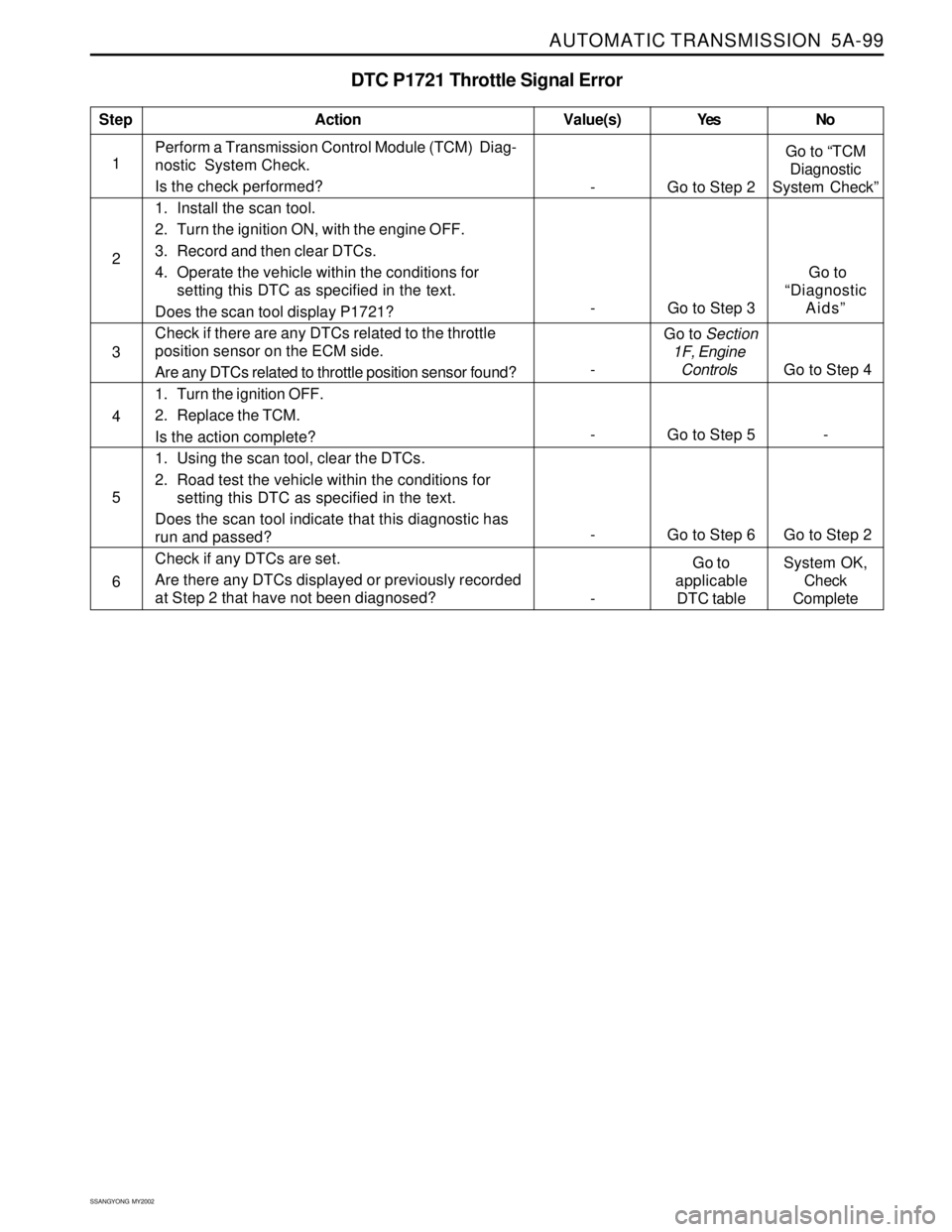
DTC P1721 Throttle Signal Error
1Perform a Transmission Control Module (TCM) Diag-
nostic System Check.
Is the check performed?
1. Install the scan tool.
2. Turn the ignition ON, with the engine OFF.
3. Record and then clear DTCs.
4. Operate the vehicle within the conditions for
setting this DTC as specified in the text.
Does the scan tool display P1721?
Check if there are any DTCs related to the throttle
position sensor on the ECM side.
Are any DTCs related to throttle position sensor found?
1. Turn the ignition OFF.
2. Replace the TCM.
Is the action complete?
1. Using the scan tool, clear the DTCs.
2. Road test the vehicle within the conditions for
setting this DTC as specified in the text.
Does the scan tool indicate that this diagnostic has
run and passed?
Check if any DTCs are set.
Are there any DTCs displayed or previously recorded
at Step 2 that have not been diagnosed?
StepAction Value(s) Yes No
2
3
- Go to Step 5 - 4
- Go to Step 6 Go to Step 2 5
6
- Go to Step 2Go to “TCM
Diagnostic
System Check”
- Go to Step 3 Go to
“Diagnostic
Aids”
- Go to Section
1F, Engine
Controls Go to Step 4
-Go to
applicable
DTC tableSystem OK,
Check
Complete
Page 1373 of 2053
TRANSFER CASE 5D1-3
SSANGYONG MY2002
A1
A2
A3
A4
A5
A6
A7
A8
A9
A10
A11
A12
B1
B2
B3
B4
B5
B6
B7
B8
B9
B10
B11
B12
B13
B14
B15
B16
B17
B18Shift motor output (- High to low: Battery voltage/ - Low to high or motor brake : Ground)
Shift motor output (- Low to high: Battery voltage/ - High to Low or motor brake : Ground)
TOD output: Electromagnetic clutch control
B (+) : Fuse F17
Ignition Voltage: Fuse F23
Shift motor output (- High to low: Battery voltage/ - Low to high or motor brake : Ground)
Shift motor output (- Low to high: Battery voltage/ - High to Low or motor brake : Ground)
Reference voltage (5V) supply to Throttle Position (TP) sensor and speed sensor
Ground
Ground
B (+) : Fuse F17
Diagnosis (K-line)
Position encoder ground
Illuminate 4WD CHECK lamp
Not in used
Mode (4H/4L) input
Position encoder 2 input
Front propeller shaft speed sensor input
Not in used
Speed sensor ground. Throttle position (TP) sensor return
Illuminate 4WD LOW indicator
CAN bus high line
CAN bus low line
Neutral position sensor signal input (A/T only)
ABS operation signal (ON/OFF)
Brake switch signal input
Position encoder 1 input
Position encoder 3 input
Rear propeller shaft speed sensor signal input
Position encoder 4 input
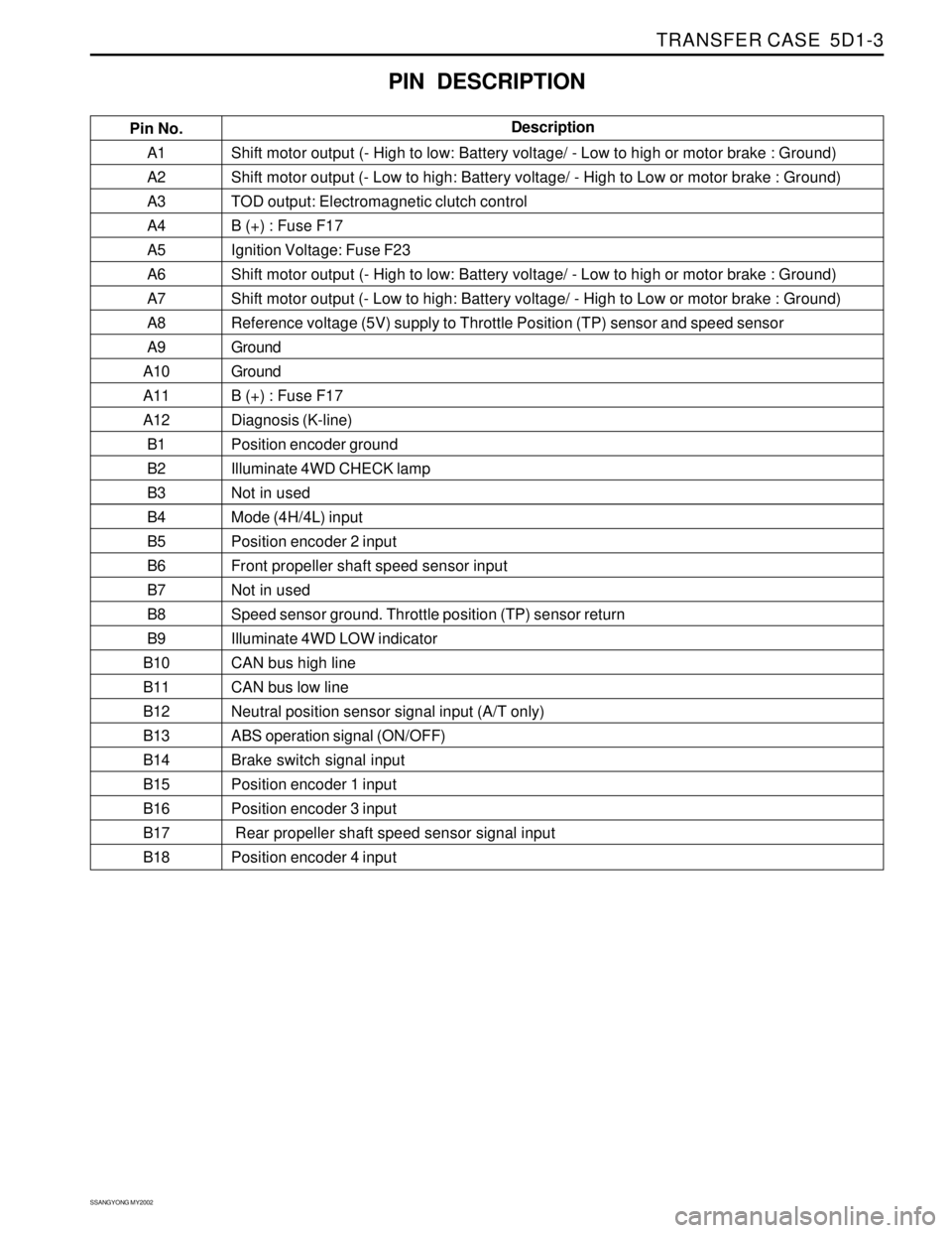
PIN DESCRIPTION
Pin No.Description
Page 1374 of 2053
SSANGYONG MY2002
5D1-4 TRANSFER CASE
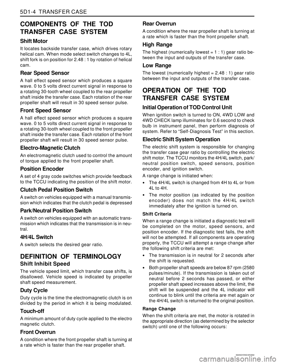
COMPONENTS OF THE TOD
TRANSFER CASE SYSTEM
Shift Motor
It locates backside transfer case, which drives rotary
helical cam. When mode select switch changes to 4L,
shift fork is on position for 2.48 : 1 by rotation of helical
cam.
Rear Speed Sensor
A hall effect speed sensor which produces a square
wave. 0 to 5 volts direct current signal in response to
a rotating 30-tooth wheel coupled to the rear propeller
shaft inside the transfer case. Each rotation of the rear
propeller shaft will result in 30 speed sensor pulse.
Front Speed Sensor
A hall effect speed sensor which produces a square
wave. 0 to 5 volts direct current signal in response to
a rotating 30-tooth wheel coupled to the front propeller
shaft inside the transfer case. Each rotation of the front
propeller shaft will result in 30 speed sensor pulse.
Electro-Magnetic Clutch
An electromagnetic clutch used to control the amount
of torque applied to the front propeller shaft.
Position Encoder
A set of 4 gray code switches which provide feedback
to the TCCU indicating the position of the shift motor.
Clutch Pedal Position Switch
A switch on vehicles equipped with a manual transmis-
sion which indicates that the clutch pedal is depressed
Park/Neutral Position Switch
A switch on vehicles equipped with an automatic trans-
mission which indicates that the transmission is in neu-
tral.
4H/4L Switch
A switch selects the desired gear ratio.
DEFINITION OF TERMINOLOGY
Shift Inhibit Speed
The vehicle speed limit, which transfer case shifts, is
disallowed. Vehicle speed is indicated by propeller
shaft speed measurement.
Duty Cycle
Duty cycle is the time the electromagnetic clutch is on
divided by the period in which it is being modulated.
Touch-off
A minimum amount of duty cycle applied to the electro
magnetic clutch.
Front Overrun
A condition where the front propeller shaft is turning at
a rate which is faster than the rear propeller shaft.
Rear Overrun
A condition where the rear propeller shaft is turning at
a rate which is faster than the front propeller shaft.
High Range
The highest (numerically lowest = 1 : 1) gear ratio be-
tween the input and outputs of the transfer case.
Low Range
The lowest (numerically highest = 2.48 : 1) gear ratio
between the input and outputs of the transfer case.
OPERATION OF THE TOD
TRANSFER CASE SYSTEM
Initial Operation of TOD Control Unit
When ignition switch is turned to ON, 4WD LOW and
4WD CHECK lamp illuminates for 0.6 second to check
bulb in instrument panel, then perform diagnosis of
system. Refer to “Self-Diagnosis Test” in this section.
Electric Shift System Operation
The electric shift system is responsible for changing
the transfer case gear ratio by controlling the electric
shift motor. The TCCU monitors the 4H/4L switch, park/
neutral position switch, speed sensors, position
encoder, and ignition switch.
A range change is initiated when:
The 4H/4L switch is changed from 4H to 4L or from
4L to 4H.
The motor position (as indicated by the position
encoder) does not match the 4H/4L switch
immediately after the ignition is turned on.
Shift Criteria
When a range change is initiated a diagnostic test will
be completed on the motor, speed sensors, and
position encoder. If the diagnostic test fails, the shift
will not be attempted. If all components are operating
properly, the TCCU will attempt a range change after
the following shift criteria are met:
The transmission is in neutral for 2 seconds after
the shift is requested.
Both propeller shaft speeds are below 87 rpm (2580
pulses/minute). If the transmission is taken out of
neutral before 2 seconds has passed, or either
propeller shaft speed increases above the limit, the
shift will be suspended and the 4L indicator will
continue to blink until the criteria are met again or
the 4H/4L switch is returned to the original position.
Range Change
When the shift criteria are met, the motor is rotated in
the appropriate direction (as determined by the selector
switch) until one of the following occurs:
Page 1375 of 2053
TRANSFER CASE 5D1-5
SSANGYONG MY2002
The motor reaches its destination.
The motor is on for 5 seconds without reaching its
destination. The shift has failed and the TCCU will
respond as default mode.
A fault occurs with either the motor or position
encoder. Refer to the diagnosis requirement.
When the motor is energized, the Ignition, 4H/4L
switch, propeller shaft speeds, and transmission
neutral inputs are ignored.
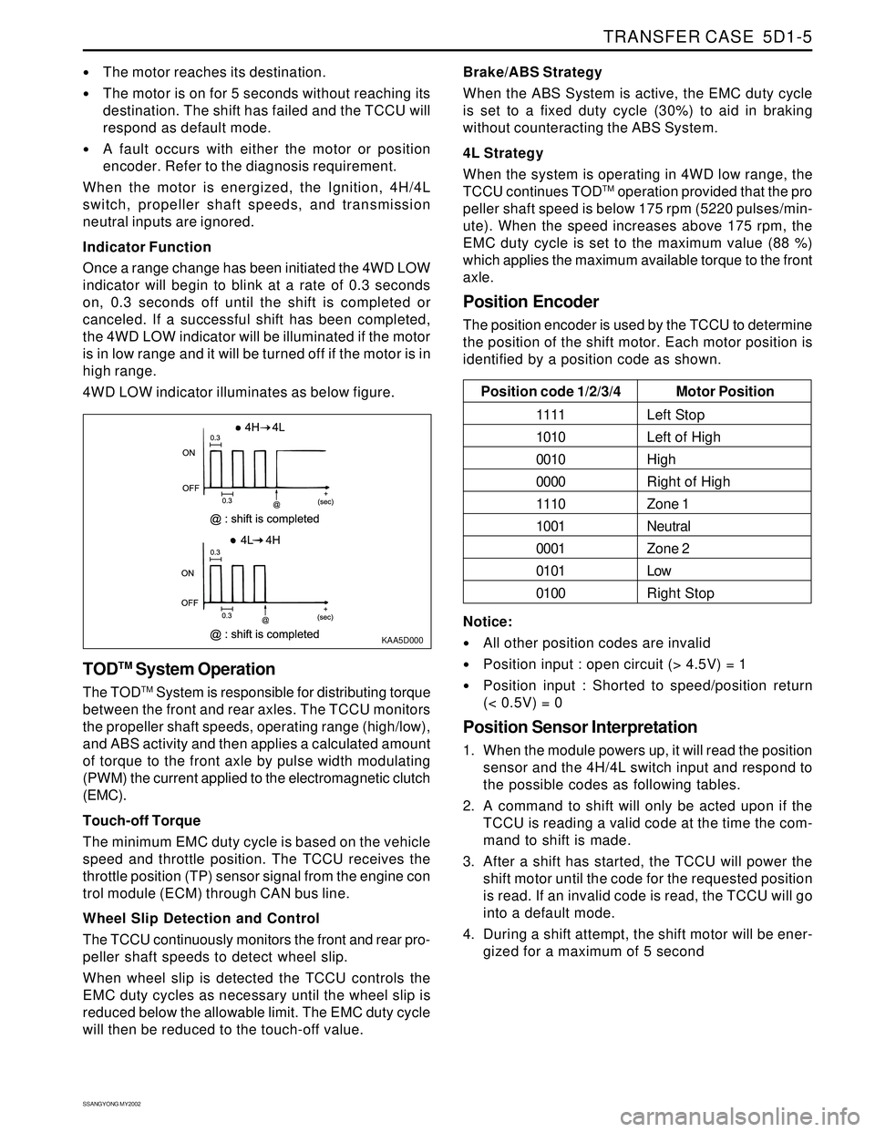
Indicator Function
Once a range change has been initiated the 4WD LOW
indicator will begin to blink at a rate of 0.3 seconds
on, 0.3 seconds off until the shift is completed or
canceled. If a successful shift has been completed,
the 4WD LOW indicator will be illuminated if the motor
is in low range and it will be turned off if the motor is in
high range.
4WD LOW indicator illuminates as below figure.
KAA5D000
TODTM System Operation
The TODTM System is responsible for distributing torque
between the front and rear axles. The TCCU monitors
the propeller shaft speeds, operating range (high/low),
and ABS activity and then applies a calculated amount
of torque to the front axle by pulse width modulating
(PWM) the current applied to the electromagnetic clutch
(EMC).
Touch-off Torque
The minimum EMC duty cycle is based on the vehicle
speed and throttle position. The TCCU receives the
throttle position (TP) sensor signal from the engine con
trol module (ECM) through CAN bus line.
Wheel Slip Detection and Control
The TCCU continuously monitors the front and rear pro-
peller shaft speeds to detect wheel slip.
When wheel slip is detected the TCCU controls the
EMC duty cycles as necessary until the wheel slip is
reduced below the allowable limit. The EMC duty cycle
will then be reduced to the touch-off value.Brake/ABS Strategy
When the ABS System is active, the EMC duty cycle
is set to a fixed duty cycle (30%) to aid in braking
without counteracting the ABS System.
4L Strategy
When the system is operating in 4WD low range, the
TCCU continues TOD
TM operation provided that the pro
peller shaft speed is below 175 rpm (5220 pulses/min-
ute). When the speed increases above 175 rpm, the
EMC duty cycle is set to the maximum value (88 %)
which applies the maximum available torque to the front
axle.
Position Encoder
The position encoder is used by the TCCU to determine
the position of the shift motor. Each motor position is
identified by a position code as shown.
Motor Position
Left Stop
Left of High
High
Right of High
Zone 1
Neutral
Zone 2
Low
Right Stop Position code 1/2/3/4
1111
1010
0010
0000
1110
1001
0001
0101
0100
Notice:
All other position codes are invalid
Position input : open circuit (> 4.5V) = 1
Position input : Shorted to speed/position return
(< 0.5V) = 0
Position Sensor Interpretation
1. When the module powers up, it will read the position
sensor and the 4H/4L switch input and respond to
the possible codes as following tables.
2. A command to shift will only be acted upon if the
TCCU is reading a valid code at the time the com-
mand to shift is made.
3. After a shift has started, the TCCU will power the
shift motor until the code for the requested position
is read. If an invalid code is read, the TCCU will go
into a default mode.
4. During a shift attempt, the shift motor will be ener-
gized for a maximum of 5 second
Page 1382 of 2053
SSANGYONG MY2002
5D1-12 TRANSFER CASE
Both Speed Sensor Faulty
If both the front and rear speed sensors are faulty con
tinuously for 0.5 seconds the 4WD CHECK lamp is
illuminated. The TCCU then responds as follows:
1. If the system is in high range the TCCU sets the
EMC touch off level based on a vehicle speed of
0 and wheel slip control is suspended.
2. If the system is in low range, the EMC duty cycle
is set to maximum until the system is shifted out
of low range.
3. All electric shift activity is halted until the Ignition
is cycled. If a shift is in progress it will be
completed.
If both speed sensors recover continuously for 0.5 sec-
ond the TCCU will function normally. The 4WD CHECK
lamp is turned off but the fault code will remain in
memory.
Electro-Magnetic Clutch Test
The electromagnetic clutch (EMC) is tested for open
circuit or short circuit to ground. If a fault is detected
continuously for 0.8 second the 4WD CHECK lamp is
turned on and all TODTM activity is halted.
If the EMC recovers continuously for 0.8 second the
TCCU will function normally. The 4WD CHECK lamp is
turned off but the fault code will remain in memory.
DIAGNOSTIC TROUBLE CODES
(DTCS)
When a fault is detected a diagnostic trouble code
(DTC) is stored in the TCCU and illuminates the 4WD
CHECK indicator. This DTC will remain in memory until
the TCCU is instructed to erase DTCs by scan tool.
Notice: DTCs can not be erased by disconnecting of
power supply to the TCCU.
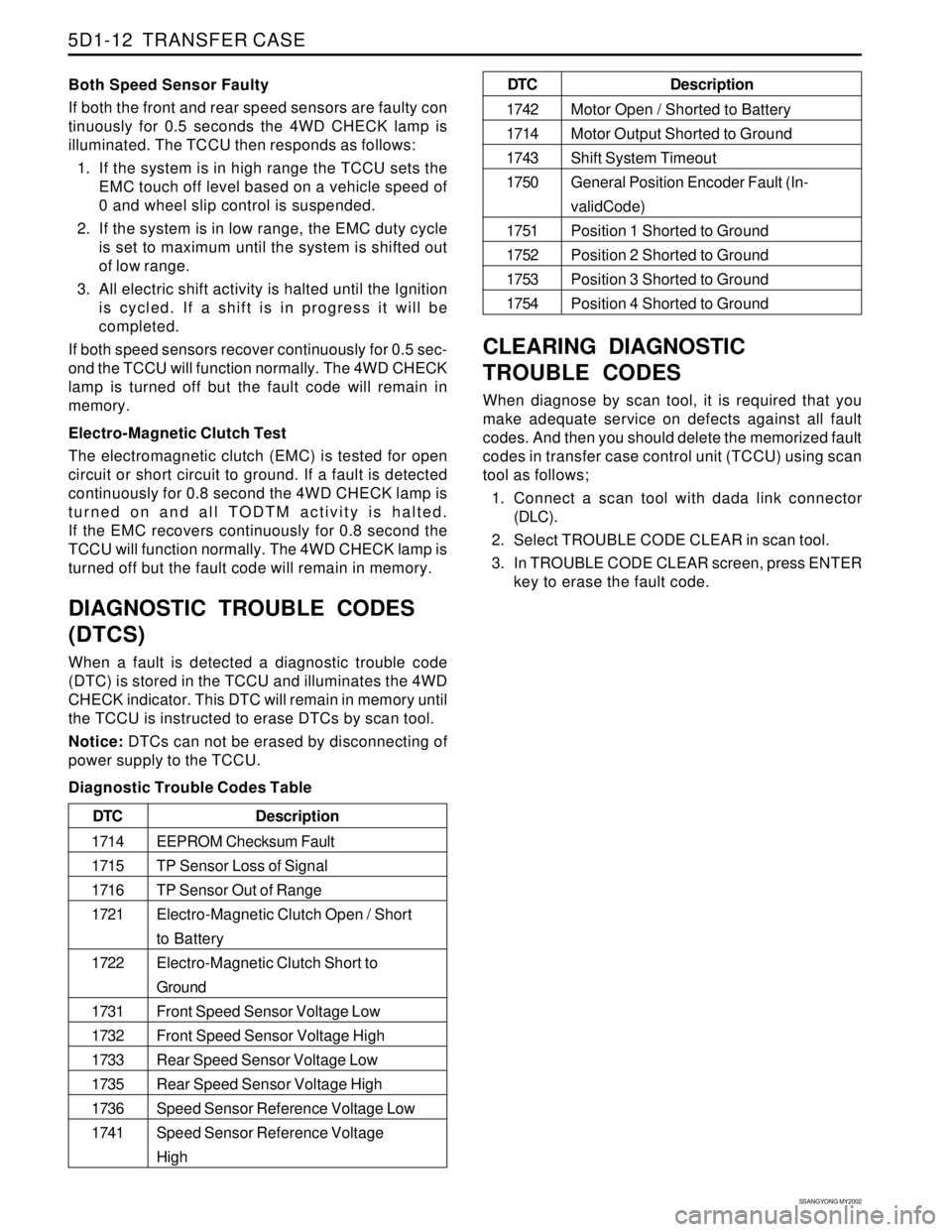
Diagnostic Trouble Codes Table
CLEARING DIAGNOSTIC
TROUBLE CODES
When diagnose by scan tool, it is required that you
make adequate service on defects against all fault
codes. And then you should delete the memorized fault
codes in transfer case control unit (TCCU) using scan
tool as follows;
1. Connect a scan tool with dada link connector
(DLC).
2. Select TROUBLE CODE CLEAR in scan tool.
3. In TROUBLE CODE CLEAR screen, press ENTER
key to erase the fault code.
Description
EEPROM Checksum Fault
TP Sensor Loss of Signal
TP Sensor Out of Range
Electro-Magnetic Clutch Open / Short
to Battery
Electro-Magnetic Clutch Short to
Ground
Front Speed Sensor Voltage Low
Front Speed Sensor Voltage High
Rear Speed Sensor Voltage Low
Rear Speed Sensor Voltage High
Speed Sensor Reference Voltage Low
Speed Sensor Reference Voltage
High DTC
1714
1715
1716
1721
1722
1731
1732
1733
1735
1736
1741
Description
Motor Open / Shorted to Battery
Motor Output Shorted to Ground
Shift System Timeout
General Position Encoder Fault (In-
validCode)
Position 1 Shorted to Ground
Position 2 Shorted to Ground
Position 3 Shorted to Ground
Position 4 Shorted to Ground DTC
1742
1714
1743
1750
1751
1752
1753
1754
Page 1472 of 2053
SSANGYONG MY2002
6C-4 POWER STEERING GEAR
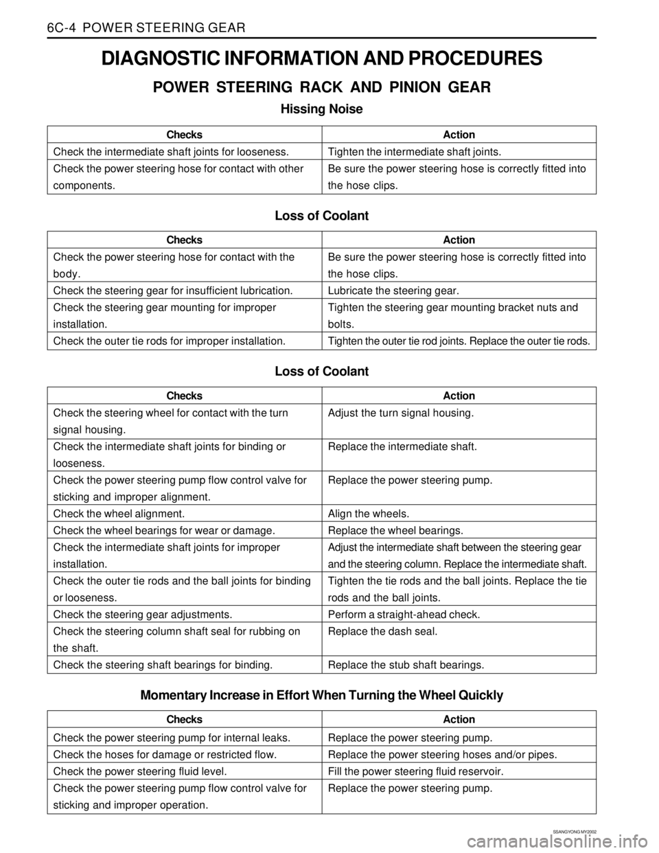
DIAGNOSTIC INFORMATION AND PROCEDURES
POWER STEERING RACK AND PINION GEAR
Hissing Noise
Check the intermediate shaft joints for looseness.
Check the power steering hose for contact with other
components.ChecksActionTighten the intermediate shaft joints.
Be sure the power steering hose is correctly fitted into
the hose clips.
Loss of Coolant
Check the power steering hose for contact with the
body.
Check the steering gear for insufficient lubrication.
Check the steering gear mounting for improper
installation.
Check the outer tie rods for improper installation.ChecksActionBe sure the power steering hose is correctly fitted into
the hose clips.
Lubricate the steering gear.
Tighten the steering gear mounting bracket nuts and
bolts.
Tighten the outer tie rod joints. Replace the outer tie rods.
Loss of Coolant
Check the steering wheel for contact with the turn
signal housing.
Check the intermediate shaft joints for binding or
looseness.
Check the power steering pump flow control valve for
sticking and improper alignment.
Check the wheel alignment.
Check the wheel bearings for wear or damage.
Check the intermediate shaft joints for improper
installation.
Check the outer tie rods and the ball joints for binding
or looseness.
Check the steering gear adjustments.
Check the steering column shaft seal for rubbing on
the shaft.
Check the steering shaft bearings for binding.ChecksActionAdjust the turn signal housing.
Replace the intermediate shaft.
Replace the power steering pump.
Align the wheels.
Replace the wheel bearings.
Adjust the intermediate shaft between the steering gear
and the steering column. Replace the intermediate shaft.
Tighten the tie rods and the ball joints. Replace the tie
rods and the ball joints.
Perform a straight-ahead check.
Replace the dash seal.
Replace the stub shaft bearings.
Check the power steering pump for internal leaks.
Check the hoses for damage or restricted flow.
Check the power steering fluid level.
Check the power steering pump flow control valve for
sticking and improper operation.ChecksActionReplace the power steering pump.
Replace the power steering hoses and/or pipes.
Fill the power steering fluid reservoir.
Replace the power steering pump.
Momentary Increase in Effort When Turning the Wheel Quickly
Page 1487 of 2053
SECTION 6E
POWER STEERING AND COLUMN
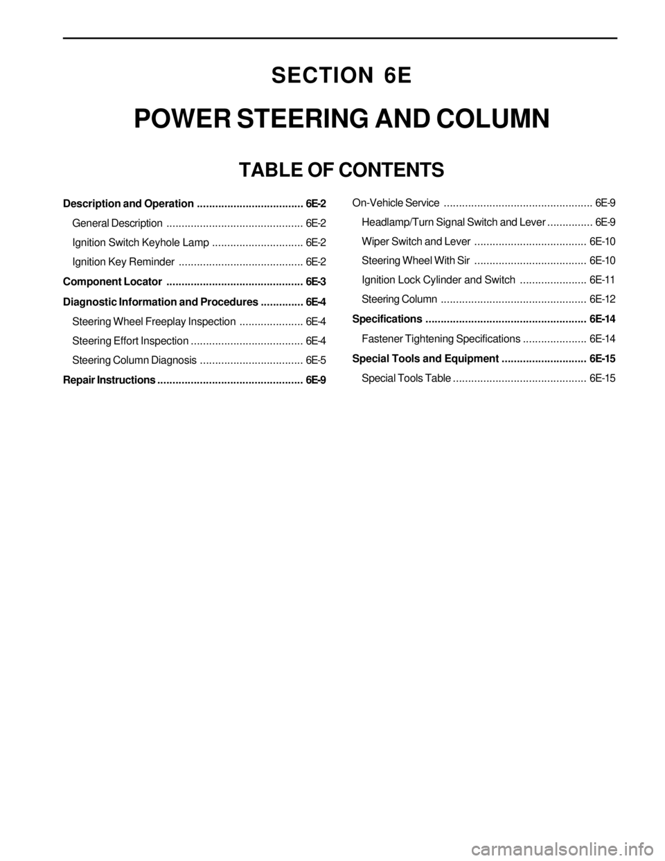
TABLE OF CONTENTS
Description and Operation...................................6E-2
General Description.............................................6E-2
Ignition Switch Keyhole Lamp..............................6E-2
Ignition Key Reminder .........................................6E-2
Component Locator.............................................6E-3
Diagnostic Information and Procedures..............6E-4
Steering Wheel Freeplay Inspection.....................6E-4
Steering Effort Inspection.....................................6E-4
Steering Column Diagnosis..................................6E-5
Repair Instructions................................................6E-9On-Vehicle Service.................................................6E-9
Headlamp/Turn Signal Switch and Lever...............6E-9
Wiper Switch and Lever.....................................6E-10
Steering Wheel With Sir.....................................6E-10
Ignition Lock Cylinder and Switch......................6E-11
Steering Column................................................6E-12
Specifications.....................................................6E-14
Fastener Tightening Specifications.....................6E-14
Special Tools and Equipment............................6E-15
Special Tools Table............................................6E-15
Page 1488 of 2053
SSANGYONG MY2002
6E-2 POWER STEERING AND COLUMN
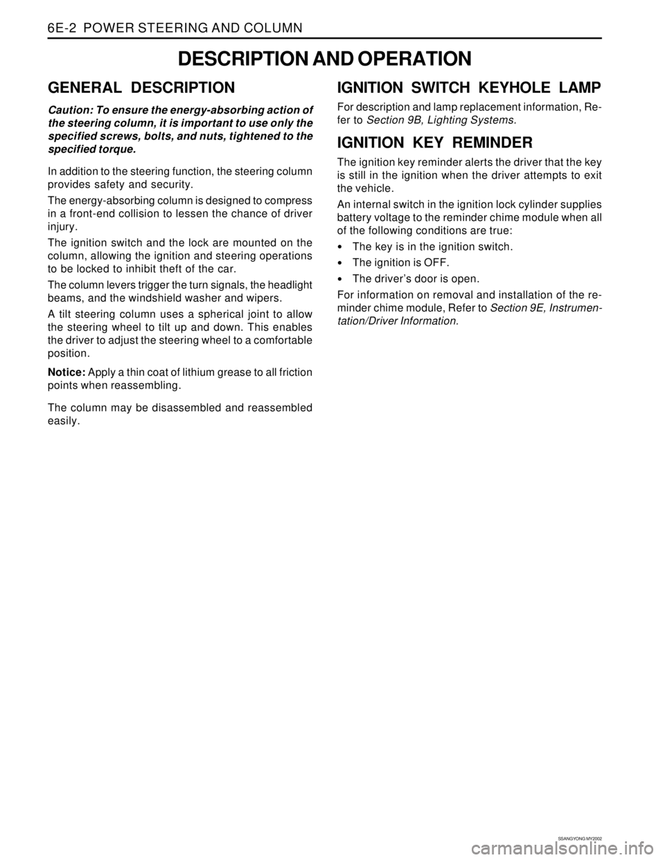
GENERAL DESCRIPTION
Caution: To ensure the energy-absorbing action of
the steering column, it is important to use only the
specified screws, bolts, and nuts, tightened to the
specified torque.
In addition to the steering function, the steering column
provides safety and security.
The energy-absorbing column is designed to compress
in a front-end collision to lessen the chance of driver
injury.
The ignition switch and the lock are mounted on the
column, allowing the ignition and steering operations
to be locked to inhibit theft of the car.
The column levers trigger the turn signals, the headlight
beams, and the windshield washer and wipers.
A tilt steering column uses a spherical joint to allow
the steering wheel to tilt up and down. This enables
the driver to adjust the steering wheel to a comfortable
position.
Notice: Apply a thin coat of lithium grease to all friction
points when reassembling.
The column may be disassembled and reassembled
easily.
DESCRIPTION AND OPERATION
IGNITION SWITCH KEYHOLE LAMP
For description and lamp replacement information, Re-
fer to Section 9B, Lighting Systems.
IGNITION KEY REMINDER
The ignition key reminder alerts the driver that the key
is still in the ignition when the driver attempts to exit
the vehicle.
An internal switch in the ignition lock cylinder supplies
battery voltage to the reminder chime module when all
of the following conditions are true:
•The key is in the ignition switch.
The ignition is OFF.
The driver’s door is open.
For information on removal and installation of the re-
minder chime module, Refer to Section 9E, Instrumen-
tation/Driver Information.