1997 SSANGYONG KORANDO turn signal
[x] Cancel search: turn signalPage 1676 of 2053
SSANGYONG MY2002
9B-2 LIGHTING SYSTEM
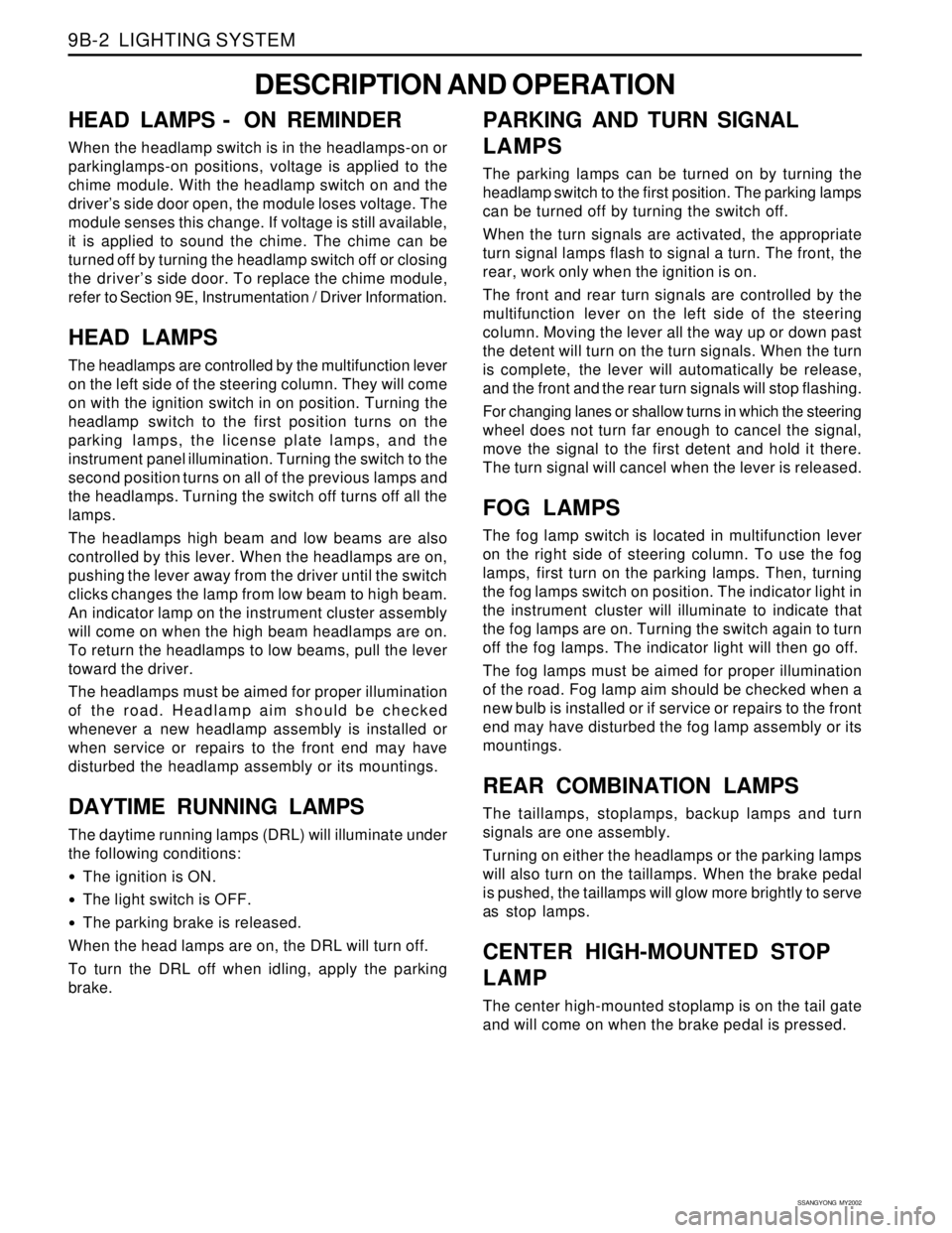
DESCRIPTION AND OPERATION
HEAD LAMPS - ON REMINDER
When the headlamp switch is in the headlamps-on or
parkinglamps-on positions, voltage is applied to the
chime module. With the headlamp switch on and the
driver’s side door open, the module loses voltage. The
module senses this change. If voltage is still available,
it is applied to sound the chime. The chime can be
turned off by turning the headlamp switch off or closing
the driver’s side door. To replace the chime module,
refer to Section 9E, Instrumentation / Driver Information.
HEAD LAMPS
The headlamps are controlled by the multifunction lever
on the left side of the steering column. They will come
on with the ignition switch in on position. Turning the
headlamp switch to the first position turns on the
parking lamps, the license plate lamps, and the
instrument panel illumination. Turning the switch to the
second position turns on all of the previous lamps and
the headlamps. Turning the switch off turns off all the
lamps.
The headlamps high beam and low beams are also
controlled by this lever. When the headlamps are on,
pushing the lever away from the driver until the switch
clicks changes the lamp from low beam to high beam.
An indicator lamp on the instrument cluster assembly
will come on when the high beam headlamps are on.
To return the headlamps to low beams, pull the lever
toward the driver.
The headlamps must be aimed for proper illumination
of the road. Headlamp aim should be checked
whenever a new headlamp assembly is installed or
when service or repairs to the front end may have
disturbed the headlamp assembly or its mountings.
DAYTIME RUNNING LAMPS
The daytime running lamps (DRL) will illuminate under
the following conditions:
The ignition is ON.
The light switch is OFF.
The parking brake is released.
When the head lamps are on, the DRL will turn off.
To turn the DRL off when idling, apply the parking
brake.
PARKING AND TURN SIGNAL
LAMPS
The parking lamps can be turned on by turning the
headlamp switch to the first position. The parking lamps
can be turned off by turning the switch off.
When the turn signals are activated, the appropriate
turn signal lamps flash to signal a turn. The front, the
rear, work only when the ignition is on.
The front and rear turn signals are controlled by the
multifunction lever on the left side of the steering
column. Moving the lever all the way up or down past
the detent will turn on the turn signals. When the turn
is complete, the lever will automatically be release,
and the front and the rear turn signals will stop flashing.
For changing lanes or shallow turns in which the steering
wheel does not turn far enough to cancel the signal,
move the signal to the first detent and hold it there.
The turn signal will cancel when the lever is released.
FOG LAMPS
The fog lamp switch is located in multifunction lever
on the right side of steering column. To use the fog
lamps, first turn on the parking lamps. Then, turning
the fog lamps switch on position. The indicator light in
the instrument cluster will illuminate to indicate that
the fog lamps are on. Turning the switch again to turn
off the fog lamps. The indicator light will then go off.
The fog lamps must be aimed for proper illumination
of the road. Fog lamp aim should be checked when a
new bulb is installed or if service or repairs to the front
end may have disturbed the fog lamp assembly or its
mountings.
REAR COMBINATION LAMPS
The taillamps, stoplamps, backup lamps and turn
signals are one assembly.
Turning on either the headlamps or the parking lamps
will also turn on the taillamps. When the brake pedal
is pushed, the taillamps will glow more brightly to serve
as stop lamps.
CENTER HIGH-MOUNTED STOP
LAMP
The center high-mounted stoplamp is on the tail gate
and will come on when the brake pedal is pressed.
Page 1682 of 2053
SSANGYONG MY2002
9B-8 LIGHTING SYSTEM
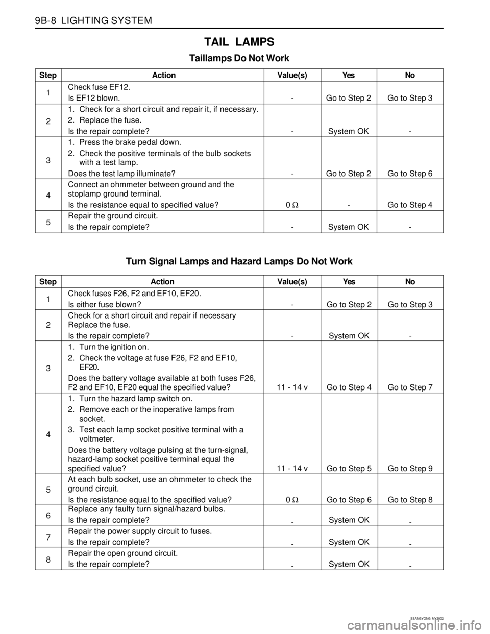
Turn Signal Lamps and Hazard Lamps Do Not Work
Step
1
2
3
4
5
6
7
8Action
Check fuses F26, F2 and EF10, EF20.
Is either fuse blown?
Check for a short circuit and repair if necessary
Replace the fuse.
Is the repair complete?
1. Turn the ignition on.
2. Check the voltage at fuse F26, F2 and EF10,
EF20.
Does the battery voltage available at both fuses F26,
F2 and EF10, EF20 equal the specified value?
1. Turn the hazard lamp switch on.
2. Remove each or the inoperative lamps from
socket.
3. Test each lamp socket positive terminal with a
voltmeter.
Does the battery voltage pulsing at the turn-signal,
hazard-lamp socket positive terminal equal the
specified value?
At each bulb socket, use an ohmmeter to check the
ground circuit.
Is the resistance equal to the specified value?
Replace any faulty turn signal/hazard bulbs.
Is the repair complete?
Repair the power supply circuit to fuses.
Is the repair complete?
Repair the open ground circuit.
Is the repair complete?Yes
Go to Step 2
System OK
Go to Step 4
Go to Step 5
Go to Step 6
System OK
System OK
System OKNo
Go to Step 3
-
Go to Step 7
Go to Step 9
Go to Step 8
-
-
- Value(s)
-
-
11 - 14 v
11 - 14 v
0 Ω
-
-
-
TAIL LAMPS
Taillamps Do Not Work
Step
1
2
3
4
5Action
Check fuse EF12.
Is EF12 blown.
1. Check for a short circuit and repair it, if necessary.
2. Replace the fuse.
Is the repair complete?
1. Press the brake pedal down.
2. Check the positive terminals of the bulb sockets
with a test lamp.
Does the test lamp illuminate?
Connect an ohmmeter between ground and the
stoplamp ground terminal.
Is the resistance equal to specified value?
Repair the ground circuit.
Is the repair complete?Yes
Go to Step 2
System OK
Go to Step 2
-
System OKNo
Go to Step 3
-
Go to Step 6
Go to Step 4
- Value(s)
-
-
-
0 Ω
-
Page 1683 of 2053
LIGHTING SYSTEM 9B-9
SSANGYONG MY2002
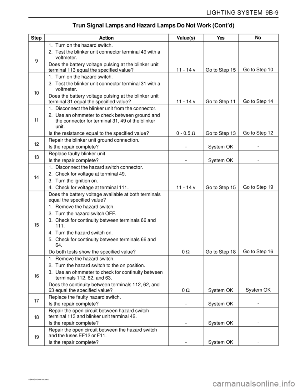
Trun Signal Lamps and Hazard Lamps Do Not Work (Cont’d)
Step
9
10
11
12
13
14
15
16
17
18
19Action
1. Turn on the hazard switch.
2. Test the blinker unit connector terminal 49 with a
voltmeter.
Does the battery voltage pulsing at the blinker unit
terminal 113 equal the specified value?
1. Turn on the hazard switch.
2. Test the blinker unit connector terminal 31 with a
voltmeter.
Does the battery voltage pulsing at the blinker unit
terminal 31 equal the specified value?
1. Disconnect the blinker unit from the connector.
2. Use an ohmmeter to check between ground and
the connector for terminal 31, 49 of the blinker
unit.
Is the resistance equal to the specified value?
Repair the blinker unit ground connection.
Is the repair complete?
Replace faulty blinker unit.
Is the repair complete?
1. Disconnect the hazard switch connector.
2. Check for voltage at terminal 49.
3. Turn the ignition on.
4. Check for voltage at terminal 111.
Does the battery voltage available at both terminals
equal the specified value?
1. Remove the hazard switch.
2. Turn the hazard switch OFF.
3. Check for continuity between terminals 66 and
111.
4. Turn the hazard switch on.
5. Check for continuity between terminals 66 and
64.
Do both tests show the specified value?
1. Remove the hazard switch.
2. Turn the hazard switch to the on position.
3. Use an ohmmeter to check for continuity between
terminals 112, 62, and 63.
Does the continuity between terminals 112, 62, and
63 equal the specified value?
Replace the faulty hazard switch.
Is the repair complete?
Repair the open circuit between hazard switch
terminal 113 and blinker unit terminal 42.
Is the repair complete?
Repair the open circuit between the hazard switch
and the fuses EF12 or F11.
Is the repair complete?Yes
Go to Step 15
Go to Step 11
Go to Step 13
System OK
System OK
Go to Step 15
Go to Step 18
System OK
System OK
System OK
System OKNo
Go to Step 10
Go to Step 14
Go to Step 12
-
-
Go to Step 19
Go to Step 16
System OK
-
-
- Value(s)
11 - 14 v
11 - 14 v
0 - 0.5 Ω
-
-
11 - 14 v
0 Ω
0 Ω
-
-
-
Page 1684 of 2053
SSANGYONG MY2002
9B-10 LIGHTING SYSTEM
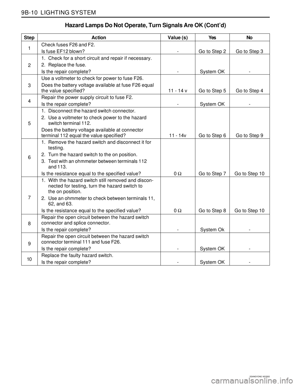
Hazard Lamps Do Not Operate, Turn Signals Are OK (Cont’d)
Step
1
2
3
4
5
6
7
8
9
10Action
Check fuses F26 and F2.
Is fuse EF12 blown?
1. Check for a short circuit and repair if necessary.
2. Replace the fuse.
Is the repair complete?
Use a voltmeter to check for power to fuse F26.
Does the battery voltage available at fuse F26 equal
the value specified?
Repair the power supply circuit to fuse F2.
Is the repair complete?
1. Disconnect the hazard switch connector.
2. Use a voltmeter to check power to the hazard
switch terminal 112.
Does the battery voltage available at connector
terminal 112 equal the value specified?
1. Remove the hazard switch and disconnect it for
testing.
2. Turn the hazard switch to the on position.
3. Test with an ohmmeter between terminals 112
and 113.
Is the resistance equal to the specified value?
1. With the hazard switch still removed and discon-
nected for testing, turn the hazard switch to
the on position.
2. Use an ohmmeter to check between terminals 11,
62, and 63.
Is the resistance equal to the specified value?
Repair the open circuit between the hazard switch
connector and splice connector.
Is the repair complete?
Repair the open circuit between the hazard switch
connector terminal 111 and fuse F26.
Is the repair complete?
Replace the faulty hazard switch.
Is the repair complete?Yes
Go to Step 2
System OK
Go to Step 5
System OK
Go to Step 6
Go to Step 7
Go to Step 8
System Ok
System OK
System OKNo
Go to Step 3
-
Go to Step 4
-
Go to Step 9
Go to Step 10
Go to Step 10
-
-
- Value (s)
-
-
11 - 14 v
-
11 - 14v
0 Ω
0 Ω
-
-
-
Page 1694 of 2053
SSANGYONG MY2002
9B-20 LIGHTING SYSTEM
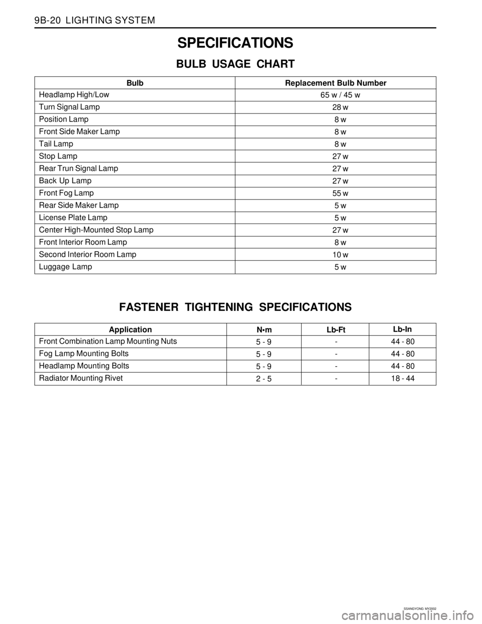
SPECIFICATIONS
BULB USAGE CHART
FASTENER TIGHTENING SPECIFICATIONS
Headlamp High/Low
Turn Signal Lamp
Position Lamp
Front Side Maker Lamp
Tail Lamp
Stop Lamp
Rear Trun Signal Lamp
Back Up Lamp
Front Fog Lamp
Rear Side Maker Lamp
License Plate Lamp
Center High-Mounted Stop Lamp
Front Interior Room Lamp
Second Interior Room Lamp
Luggage LampBulbReplacement Bulb Number65 w / 45 w
28 w
8 w
8 w
8 w
27 w
27 w
27 w
55 w
5 w
5 w
27 w
8 w
10 w
5 w
Front Combination Lamp Mounting Nuts
Fog Lamp Mounting Bolts
Headlamp Mounting Bolts
Radiator Mounting RivetApplication
Nm
5 - 9
5 - 9
5 - 9
2 - 5-
-
-
-44 - 80
44 - 80
44 - 80
18 - 44 Lb-FtLb-In
Page 1699 of 2053
LIGHTING SYSTEM 9B-25
SSANGYONG MY2002
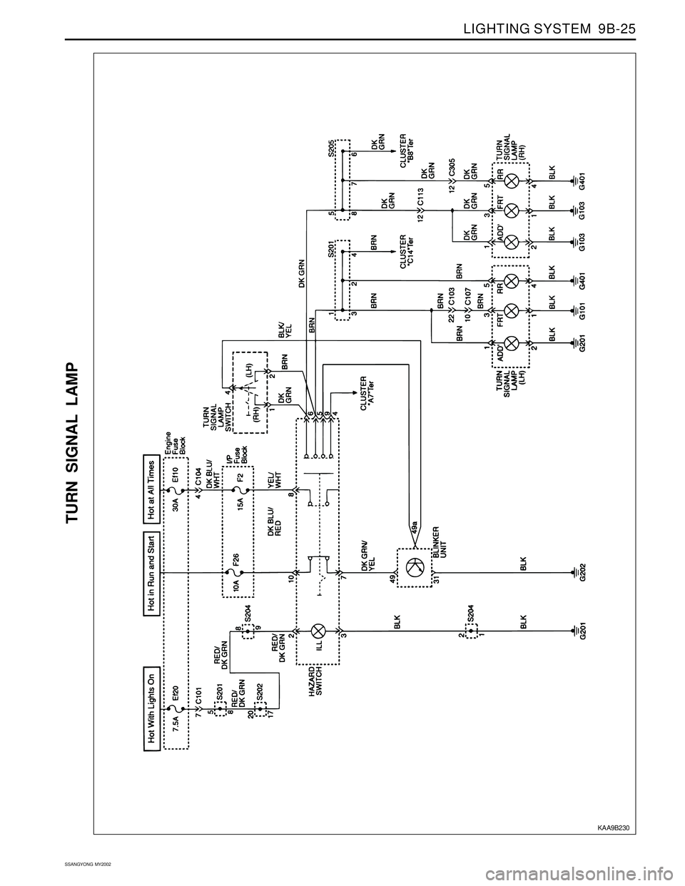
TURN SIGNAL LAMP
KAA9B230
Page 1735 of 2053
SSANGYONG MY2002
9E-18 INSTRUMENTATION, DRIVER INFORMATION
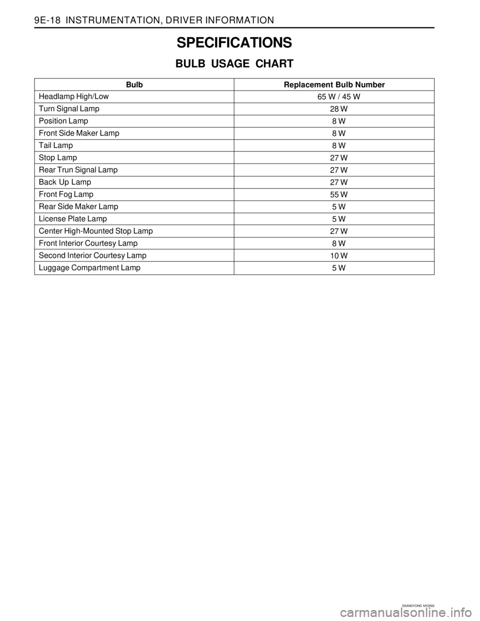
SPECIFICATIONS
BULB USAGE CHART
Headlamp High/Low
Turn Signal Lamp
Position Lamp
Front Side Maker Lamp
Tail Lamp
Stop Lamp
Rear Trun Signal Lamp
Back Up Lamp
Front Fog Lamp
Rear Side Maker Lamp
License Plate Lamp
Center High-Mounted Stop Lamp
Front Interior Courtesy Lamp
Second Interior Courtesy Lamp
Luggage Compartment LampBulbReplacement Bulb Number65 W / 45 W
28 W
8 W
8 W
8 W
27 W
27 W
27 W
55 W
5 W
5 W
27 W
8 W
10 W
5 W
Page 1849 of 2053
SSANGYONG MY2002
9T1-2 REMOTE KEYLESS ENTRY AND ANTI-THEFT SYSTEM
DESCRIPTION AND OPERATION
REMOTE KEYLESS ENTRY AND
ANTI-THEFT SYSTEM
The remote keyless entry and anti-theft system can
perform the following functions:
•Remotely lock and unlock the vehicle doors by
means of a hand-held, high-frequency transmitter.
Sense intrusion into the vehicle through the doors
or the hood.
Activate a warning if an intrusion is detected.
Automatically relock the doors if thedoor or the
tail gate is not opened within 30 seconds after the
vehicle has been unlocked by remote keyless
entry.
Help the driver find the vehicle in a parking area.
The remote keyless entry system consist of the
following components:
STICS.
Remote keyless entry system receiver.
Hand-held transmitter.
Tailgate open switch.
Door contact switch.
Siren.
Hood open switch
Key reminder switch.
Antenna.
STICS can perform the following functions:
1. Wiper INT sening vehicle speed.
By operating INT tiem control volume, variable
time will be changed within 1.5-20 seconds
2. Washer relating wiper.
3. Dimming room lamp.
When room lamp is coupled with door, it truns on
if door is opened. After closing the door it
maintains 2 seconds of lighting and dims off
whithin 3 seconds.
4. Time delayed power window control.
Power window can be operated within 30 seconds
after truning the IGN 1 switch from ON to OFF. If
driver/passenger’s door is opened within the 30
seconds from that moment.
5. Rear defogger timer.
The rear defogger will be operated for 12 min. by
turning ON the defogger switch while engine is
running.
Defogger will be stopped by pushing the switch
again.
The defogger will be operated 6 mim, if push ON
the switch within 10 min. after 12 min. of operation.6. Seat belt waring.
The warning lamp will be turned on for about 6
sec. With an intermittent chime bell when the IGN.
Switch is ON unless fastening the seat belt.
7. parking brake warning.
The indicator lamp will flash if drive while the
parking brake is applied.
8. Tail lamp lighting warning.
When the driver’s door is opened while the tail
lamp is still ON, the buzzer operates intermittently.
In this condition, the door will be automatically
unlock when it locked.
9. Door ajar warning.
The indicator lamp will be blinking when the door
is not closed completely and driving.
10. IGN key reminder.
The chime will be operated intermittently if the
driver’s door is opened while the IGN key is still
remain-ing in the ignition switch. In this condition,
the door will be automatically unlocked when it
locked.
11. Central door lock.
All doors will be locked/unlocked by locking/
unlocking the driver’s or passenger’s door.
12. coupled with REKES.
Being coupled with REKES (remote keyless entry
system), all doors will be locked/unlocked
according to signals of transmitter when the
ignition key is not inserted.
13. iginition key hole illumination.
coupled with door switch, ignition key hole
illumination lamp will trun on when the driver ’s
door is opened and will dim off after 10 sec. After
closing the door.
14. Auto door lock.
All doors will be locked automatically if the vehicle
speed reaches 50 km/h though the doors are in
unlock.
15. Auto door unlock.
All doors will be automatically unlock if the vehicle
crashes while driving (over 15km/h).
Operate the burglar alarm.
1. Burglar alarm must operate immediately when the
door, tailgate or hood is opened with improper
ways after all doors and hood were closed and
continued this status for 1 seconds.
2. If the tailgate is opened by key when the system
is on the burglar alarm cindition, the sysem must
be changed to the second burglar alarm condition
frim normal condition.