1997 SSANGYONG KORANDO transmission oil
[x] Cancel search: transmission oilPage 1141 of 2053
5A-46 AUTOMATIC TRANSMISSION
SSANGYONG MY2002
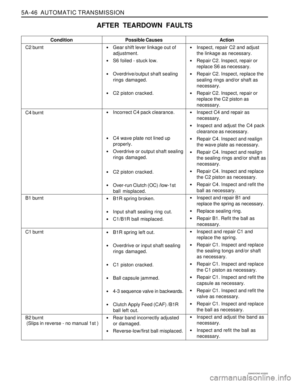
AFTER TEARDOWN FAULTS
Condition
C2 burntPossible Causes
Gear shift lever linkage out of
adjustment.
S6 foiled - stuck low.
Overdrive/output shaft sealing
rings damaged.
C2 piston cracked.
Incorrect C4 pack clearance.
C4 wave plate not lined up
properly.
Overdrive or output shaft sealing
rings damaged.
C2 piston cracked.
Over-run Clutch (OC) /low-1st
ball misplaced.
B1R spring broken.
Input shaft sealing ring cut.
C1/B1R ball misplaced.
B1R spring left out.
Overdrive or input shaft sealing
rings damaged.
C1 piston cracked.
Ball capsule jammed.
4-3 sequence valve in backwards.
Clutch Apply Feed (CAF) /B1R
ball left out.
Rear band incorrectly adjusted
or damaged.
Reverse-low/first ball misplaced.Action
Inspect, repair C2 and adjust
the linkage as necessary.
Repair C2. Inspect, repair or
replace S6 as necessary.
Repair C2. Inspect, replace the
sealing rings and/or shaft as
necessary.
Repair C2. Inspect, repair or
replace the C2 piston as
necessary.
Inspect C4 and repair as
necessary.
Inspect and adjust the C4 pack
clearance as necessary.
Repair C4. Inspect and realign
the wave plate as necessary.
Repair C4. Inspect and realign
the sealing rings and/or shaft as
necessary.
Repair C4. Inspect and replace
the C2 piston as necessary.
Repair C4. Inspect and refit the
ball as necessary.
Inspect and repair B1 and
replace the spring as necessary.
Replace sealing ring.
Repair B1. Refit the ball as
necessary.
Inspect and repair C1 and
replace the spring.
Repair C1. Inspect and replace
the sealing tongs and/or shaft
as necessary.
Repair C1. Inspect and replace
the C1 piston as necessary.
Repair C1. Inspect and refit the
capsule as necessary.
Repair C1. Inspect and refit the
valve as necessary.
Repair C1. Inspect and replace
the ball as necessary.
Inspect and adjust the band as
necessary.
Inspect and refit the ball as
necessary.
C4 burnt
B1 burnt
C1 burnt
B2 burnt
(Slips in reverse - no manual 1st )
Page 1157 of 2053
5A-62 AUTOMATIC TRANSMISSION
SSANGYONG MY2002
Circuit Description
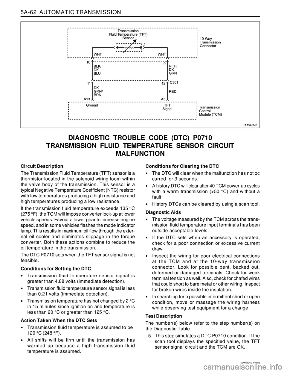
The Transmission Fluid Temperature (TFT) sensor is a
thermistor located in the solenoid wiring loom within
the valve body of the transmission. This sensor is a
typical Negative Temperature Coefficient (NTC) resistor
with low temperatures producing a high resistance and
high temperatures producing a low resistance.
If the transmission fluid temperature exceeds 135 °C
(275 °F), the TCM will impose converter lock-up at lower
vehicle speeds. Favour a lower gear to increase engine
speed, and in some vehicles flashes the mode indicator
lamp. This results in maximum oil flow through the exter-
nal oil cooler and eliminates slippage in the torque
converter. Both these actions combine to reduce the
oil temperature in the transmission.
The DTC P0710 sets when the TFT sensor signal is not
feasible.
Conditions for Setting the DTC
Transmission fluid temperature sensor signal is
greater than 4.88 volts (immediate detection).
Transmission fluid temperature sensor signal is less
than 0.21 volts (immediate detection).
Transmission temperature has not changed by 2 °C
in 15 minutes since ignition on and temperature is
less than 20 °C or greater than 125 °C.
Action Taken When the DTC Sets
Transmission fluid temperature is assumed to be
120 °C (248 °F).
All shifts will be firm until the transmission has
warmed up because a high transmission fluid
temperature is assumed.
DIAGNOSTIC TROUBLE CODE (DTC) P0710
TRANSMISSION FLUID TEMPERATURE SENSOR CIRCUIT
MALFUNCTION
Conditions for Clearing the DTC
The DTC will clear when the malfunction has not oc
curred for 3 seconds.
A history DTC will clear after 40 TCM power-up cycles
with a warm transmission (>50 °C) and without a
fault.
History DTCs can be cleared by using a scan tool.
Diagnostic Aids
The voltage measured by the TCM across the trans-
mission fluid temperature input terminals has been
outside acceptable levels.
If the DTC sets when an accessory is operated,
check for a poor connection or excessive current
draw.
Inspect the wiring for poor electrical connections
at the TCM and at the 10-way transmission
connector. Look for possible bent, backed out,
deformed or damaged terminals. Check for weak
terminal tension as well. Also, check for chafed wires
that could short to bare metal or other wiring. Inspect
for broken wires inside the insulation.
In searching for a possible intermittent short or open
condition, move or massage the wiring harness
while observing test equipment for a change.
Test Description
The number(s) below refer to the step number(s) on
the Diagnostic Table.
5. This step simulates a DTC P0710 condition. If the
scan tool displays the specified value, the TFT
sensor signal circuit and the TCM are OK.
KAA5A5M0
Page 1246 of 2053
5A-158 AUTOMATIC TRANSMISSION
SSANGYONG MY2002
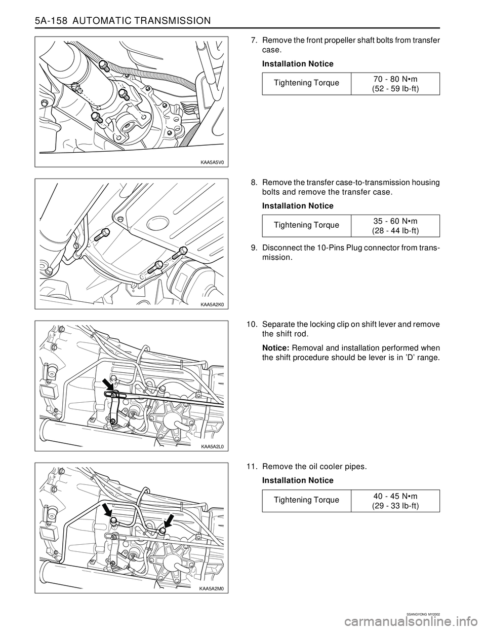
8. Remove the transfer case-to-transmission housing
bolts and remove the transfer case.
Installation Notice
10. Separate the locking clip on shift lever and remove
the shift rod.
Notice: Removal and installation performed when
the shift procedure should be lever is in ’D’ range.
11. Remove the oil cooler pipes.
Installation Notice 9. Disconnect the 10-Pins Plug connector from trans-
mission.
7. Remove the front propeller shaft bolts from transfer
case.
Installation Notice
KAA5A5V0
KAA5A2K0
KAA5A2L0
KAA5A2M0
Tightening Torque70 - 80 Nm
(52 - 59 lb-ft)
Tightening Torque35 - 60 Nm
(28 - 44 lb-ft)
Tightening Torque40 - 45 Nm
(29 - 33 lb-ft)
Page 1255 of 2053
5A-160 AUTOMATIC TRANSMISSION
SSANGYONG MY2002
UNIT REPAIR
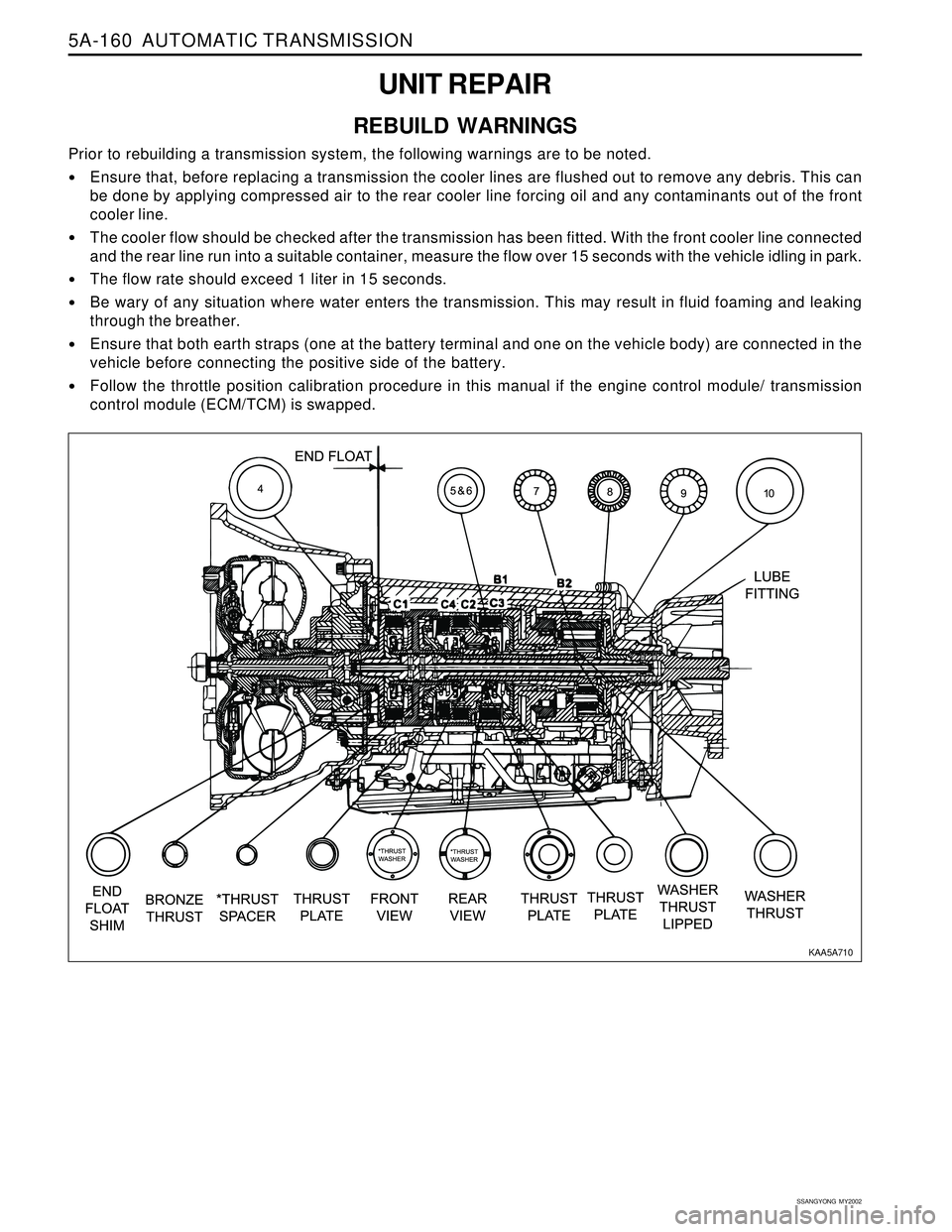
REBUILD WARNINGS
Prior to rebuilding a transmission system, the following warnings are to be noted.
Ensure that, before replacing a transmission the cooler lines are flushed out to remove any debris. This can
be done by applying compressed air to the rear cooler line forcing oil and any contaminants out of the front
cooler line.
The cooler flow should be checked after the transmission has been fitted. With the front cooler line connected
and the rear line run into a suitable container, measure the flow over 15 seconds with the vehicle idling in park.
The flow rate should exceed 1 liter in 15 seconds.
Be wary of any situation where water enters the transmission. This may result in fluid foaming and leaking
through the breather.
Ensure that both earth straps (one at the battery terminal and one on the vehicle body) are connected in the
vehicle before connecting the positive side of the battery.
Follow the throttle position calibration procedure in this manual if the engine control module/ transmission
control module (ECM/TCM) is swapped.
KAA5A710
Page 1256 of 2053
AUTOMATIC TRANSMISSION 5A-161
SSANGYONG MY2002
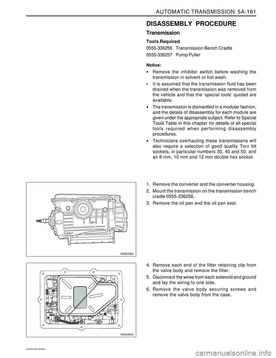
DISASSEMBLY PROCEDURE
Transmission
Tools Required
0555-336256Transmission Bench Cradle
0555-336257Pump Puller
Notice:
Remove the inhibitor switch before washing the
transmission in solvent or hot wash.
It is assumed that the transmission fluid has been
drained when the transmission was removed from
the vehicle and that the ‘special tools’ quoted are
available.
The transmission is dismantled in a modular fashion,
and the details of disassembly for each module are
given under the appropriate subject. Refer to Special
Tools Table in this chapter for details of all special
tools required when performing disassembly
procedures.
Technicians overhauling these transmissions will
also require a selection of good quality Torx bit
sockets, in particular numbers 30, 40 and 50, and
an 8 mm, 10 mm and 12 mm double hex socket.
1. Remove the converter and the converter housing.
2. Mount the transmission on the transmission bench
cradle 0555-336256.
3. Remove the oil pan and the oil pan seal.
4. Remove each end of the filter retaining clip from
the valve body and remove the filter.
5. Disconnect the wires from each solenoid and ground
and lay the wiring to one side.
6. Remove the valve body securing screws and
remove the valve body from the case.
KAA5A500
KAA5A510
Page 1292 of 2053
AUTOMATIC TRANSMISSION 5A-197
SSANGYONG MY2002
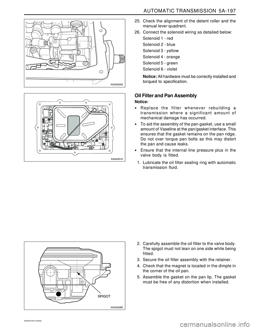
2. Carefully assemble the oil filter to the valve body.
The spigot must not lean on one side while being
fitted.
3. Secure the oil filter assembly with the retainer.
4. Check that the magnet is located in the dimple in
the corner of the oil pan.
5. Assemble the gasket on the pan lip. The gasket
must be free of any distortion when installed. 25. Check the alignment of the detent roller and the
manual lever quadrant.
26. Connect the solenoid wiring as detailed below:
Solenoid 1 - red
Solenoid 2 - bIue
Solenoid 3 - yellow
Solenoid 4 - orange
Solenoid 5 - green
Solenoid 6 - violet
Notice: All hardware must be correctly installed and
torqued to specification.
Oil Filter and Pan Assembly
Notice:
Replace the filter whenever rebuilding a
transmission where a significant amount of
mechanical damage has occurred.
To aid the assembly of the pan gasket, use a small
amount of Vaseline at the pan/gasket interface. This
ensures that the gasket remains on the pan ridge.
Do not over torque pan bolts as this may distort
the pan and cause leaks.
Ensure that the internal line pressure plus in the
valve body is fitted.
1. Lubricate the oil filter sealing ring with automatic
transmission fluid.
KAA5A2B0 KAA5A2A0
KAA5A510
Page 1293 of 2053
5A-198 AUTOMATIC TRANSMISSION
SSANGYONG MY2002
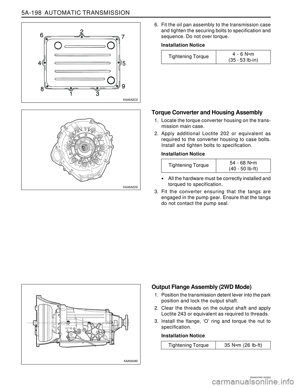
Torque Converter and Housing Assembly
1. Locate the torque converter housing on the trans-
mission main case.
2. Apply additional Loctite 202 or equivalent as
required to the converter housing to case bolts.
Install and tighten bolts to specification.
Installation Notice
All the hardware must be correctly installed and
torqued to specification.
3. Fit the converter ensuring that the tangs are
engaged in the pump gear. Ensure that the tangs
do not contact the pump seal.
Output Flange Assembly (2WD Mode)
1. Position the transmission detent lever into the park
position and lock the output shaft.
2. Clear the threads on the output shaft and apply
Loctite 243 or equivalent as required to threads.
3. Install the flange, ‘O’ ring and torque the nut to
specification.
Installation Notice
6. Fit the oil pan assembly to the transmission case
and tighten the securing bolts to specification and
sequence. Do not over torque.
Installation Notice
KAA5A2C0
KAA5A2D0
KAA5A040
Tightening Torque4 - 6 Nm
(35 - 53 lb-in)
Tightening Torque54 - 68 Nm
(40 - 50 lb-ft)
Tightening Torque 35 Nm (26 lb-ft)
Page 1300 of 2053
AUTOMATIC TRANSMISSION 5A-205
SSANGYONG MY2002
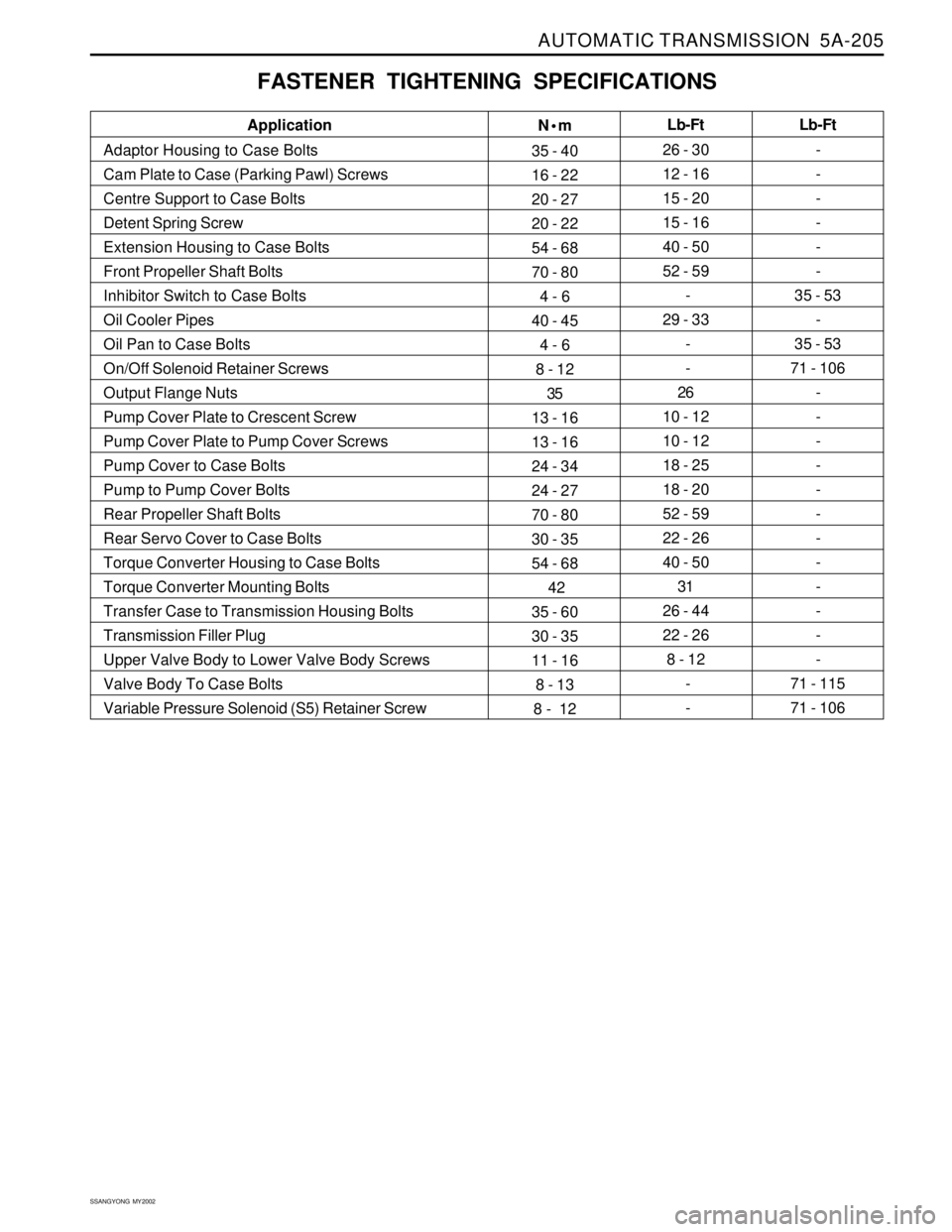
FASTENER TIGHTENING SPECIFICATIONS
N•m
35 - 40
16 - 22
20 - 27
20 - 22
54 - 68
70 - 80
4 - 6
40 - 45
4 - 6
8 - 12
35
13 - 16
13 - 16
24 - 34
24 - 27
70 - 80
30 - 35
54 - 68
42
35 - 60
30 - 35
11 - 16
8 - 13
8 - 12Lb-Ft
26 - 30
12 - 16
15 - 20
15 - 16
40 - 50
52 - 59
-
29 - 33
-
-
26
10 - 12
10 - 12
18 - 25
18 - 20
52 - 59
22 - 26
40 - 50
31
26 - 44
22 - 26
8 - 12
-
- Application
Adaptor Housing to Case Bolts
Cam Plate to Case (Parking Pawl) Screws
Centre Support to Case Bolts
Detent Spring Screw
Extension Housing to Case Bolts
Front Propeller Shaft Bolts
Inhibitor Switch to Case Bolts
Oil Cooler Pipes
Oil Pan to Case Bolts
On/Off Solenoid Retainer Screws
Output Flange Nuts
Pump Cover Plate to Crescent Screw
Pump Cover Plate to Pump Cover Screws
Pump Cover to Case Bolts
Pump to Pump Cover Bolts
Rear Propeller Shaft Bolts
Rear Servo Cover to Case Bolts
Torque Converter Housing to Case Bolts
Torque Converter Mounting Bolts
Transfer Case to Transmission Housing Bolts
Transmission Filler Plug
Upper Valve Body to Lower Valve Body Screws
Valve Body To Case Bolts
Variable Pressure Solenoid (S5) Retainer ScrewLb-Ft
-
-
-
-
-
-
35 - 53
-
35 - 53
71 - 106
-
-
-
-
-
-
-
-
-
-
-
-
71 - 115
71 - 106