1997 SSANGYONG KORANDO transmission oil
[x] Cancel search: transmission oilPage 1099 of 2053
AUTOMATIC TRANSMISSION 5A-5
SSANGYONG MY2002
Engine Speed
The engine speed signal is derived from the Control-
ler Area Network (CAN) via Engine Control Module
(ECM).
Vehicle Speed
The vehicle speed sensor, which is located in the
transfer case, sends the output shaft speed signal
to the Engine Control Module (ECM). The information
is then transferred to the TCM via the CAN.
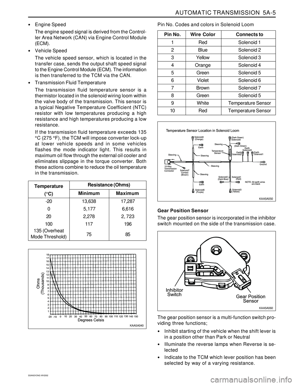
Transmission Fluid Temperature
The transmission fluid temperature sensor is a
thermistor located in the solenoid wiring loom within
the valve body of the transmission. This sensor is
a typical Negative Temperature Coefficient (NTC)
resistor with low temperatures producing a high
resistance and high temperatures producing a low
resistance.
If the transmission fluid temperature exceeds 135
°C (275 °F), the TCM will impose converter lock-up
at lower vehicle speeds and in some vehicles
flashes the mode indicator light. This results in
maximum oil flow through the external oil cooler and
eliminates slippage in the torque converter. Both
these actions combine to reduce the oil temperature
in the transmission.
Minimum Temperature
(°C)Resistance (Ohms)
-20
0
20
100
135 (Overheat
Mode Threshold)13,638
5,177
2,278
117
75
Maximum
17,287
6,616
2, 723
196
85
Pin No. Wire ColorConnects to
1 Red Solenoid 1
2 BlueSolenoid 2
3 YellowSolenoid 3
4 OrangeSolenoid 4
5 GreenSolenoid 5
6 VioletSolenoid 6
7 BrownSolenoid 7
8 GreenSolenoid 5
9 White Temperature Sensor
10 Red Temperature Sensor
Pin No. Codes and colors in Solenoid Loom
KAA5A040KAA5A050
Gear Position Sensor
The gear position sensor is incorporated in the inhibitor
switch mounted on the side of the transmission case.
Inhibit starting of the vehicle when the shift lever is
in a position other than Park or Neutral
Illuminate the reverse lamps when Reverse is se-
lected
Indicate to the TCM which lever position has been
selected by way of a varying resistance. The gear position sensor is a multi-function switch pro-
viding three functions;
KAA5A060
Page 1102 of 2053
5A-8 AUTOMATIC TRANSMISSION
SSANGYONG MY2002
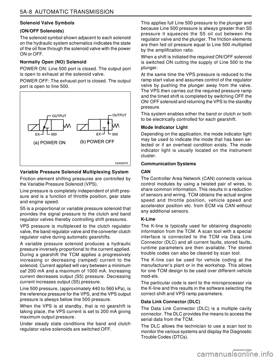
Solenoid Valve Symbols
(ON/OFF Solenoids)
The solenoid symbol shown adjacent to each solenoid
on the hydraulic system schematics indicates the state
of the oil flow through the solenoid valve with the power
ON or OFF.
Normally Open (NO) Solenoid
POWER ON: Line 500 port is closed. The output port
is open to exhaust at the solenoid valve.
POWER OFF: The exhaust port is closed. The output
port is open to line 500.
Variable Pressure Solenoid Multiplexing System
Friction element shifting pressures are controlled by
the Variable Pressure Solenoid (VPS).
Line pressure is completely independent of shift pres-
sure and is a function of throttle position, gear state
and engine speed.
S5 is a proportional or variable pressure solenoid that
provides the signal pressure to the clutch and band
regulator valves thereby controlling shift pressures.
VPS pressure is multiplexed to the clutch regulator
valve, the band regulator valve and the converter clutch
regulator valve during automatic gearshifts.
A variable pressure solenoid produces a hydraulic
pressure inversely proportional to the current applied.
During a gearshift the TCM applies a progressively
increasing or decreasing (ramped) current to the
solenoid. Current applied will vary between a minimum
oaf 200 mA and a maximum of 1000 mA. Increasing
current decreases output (S5) pressure. Decreasing
current increases output (S5) pressure.
Line 500 pressure, (approximately 440 to 560 kPa), is
the reference pressure for the VPS, and the VPS output
pressure is always below line 500 pressure.
When the VPS is at standby, that is no gearshift is
taking place, the VPS current is set to 200 mA giving
maximum output pressure.
Under steady state conditions the band and clutch
regulator valve solenoids are switched OFF.This applies full Line 500 pressure to the plunger and
because Line 500 pressure is always greater than S5
pressure it squeezes the S5 oil out between the
regulator valve and the plunger. The friction elements
are then fed oil pressure equal to Line 500 multiplied
by the amplification ratio.
When a shift is initiated the required ON/OFF solenoid
is switched ON cutting the supply of Line 500 to the
plunger.
At the same time the VPS pressure is reduced to the
ramp start value and assumes control of the regulator
valve by pushing the plunger away from the valve.
The VPS then carries out the required pressure ramp
and the timed shift is completed by switching OFF the
ON/ OFF solenoid and returning the VPS to the standby
pressure.
This system enables either the band or clutch or both
to be electrically controlled for each gearshift.
Mode Indicator Light
Depending on the application, the mode indicator light
may be used to indicate the mode that has been se-
lected or if an overheat condition exists. The mode
indicator light is usually located on the instrument
cluster.
Communication Systems
CAN
The Controller Area Network (CAN) connects various
control modules by using a twisted pair of wires, to
share common information. This results in a reduction
of sensors and wiring. TCM obtains the actual engine
speed and throttle position, vehicle speed and
accelerator position etc. from ECM via CAN without
any additional sensors.
K-Line
The K-line is typically used for obtaining diagnostic
information from the TCM. A scan tool with a special
interface is connected to the TCM via Data Link
Connector (DLC) and all current faults, stored faults,
runtime parameters are then available. The stored
trouble codes can also be cleared by scan tool.
The K-line can be used for vehicle coding at the
manufacturer’s plant or in the workshop. This allows
for one TCM design to be used over different vehicle
mod-els.
The particular code is sent to the microprocessor via
the K-line and this results in the software selecting the
correct shift and VPS ramp parameters.
Data Link Connector (DLC)
The Data Link Connector (DLC) is a multiple cavity
connector. The DLC provides the means to access the
serial data from the TCM.
The DLC allows the technician to use a scan tool to
monitor the various systems and display the Diagnostic
Trouble Codes (DTCs).
KAA5A070
Page 1105 of 2053
AUTOMATIC TRANSMISSION 5A-11
SSANGYONG MY2002
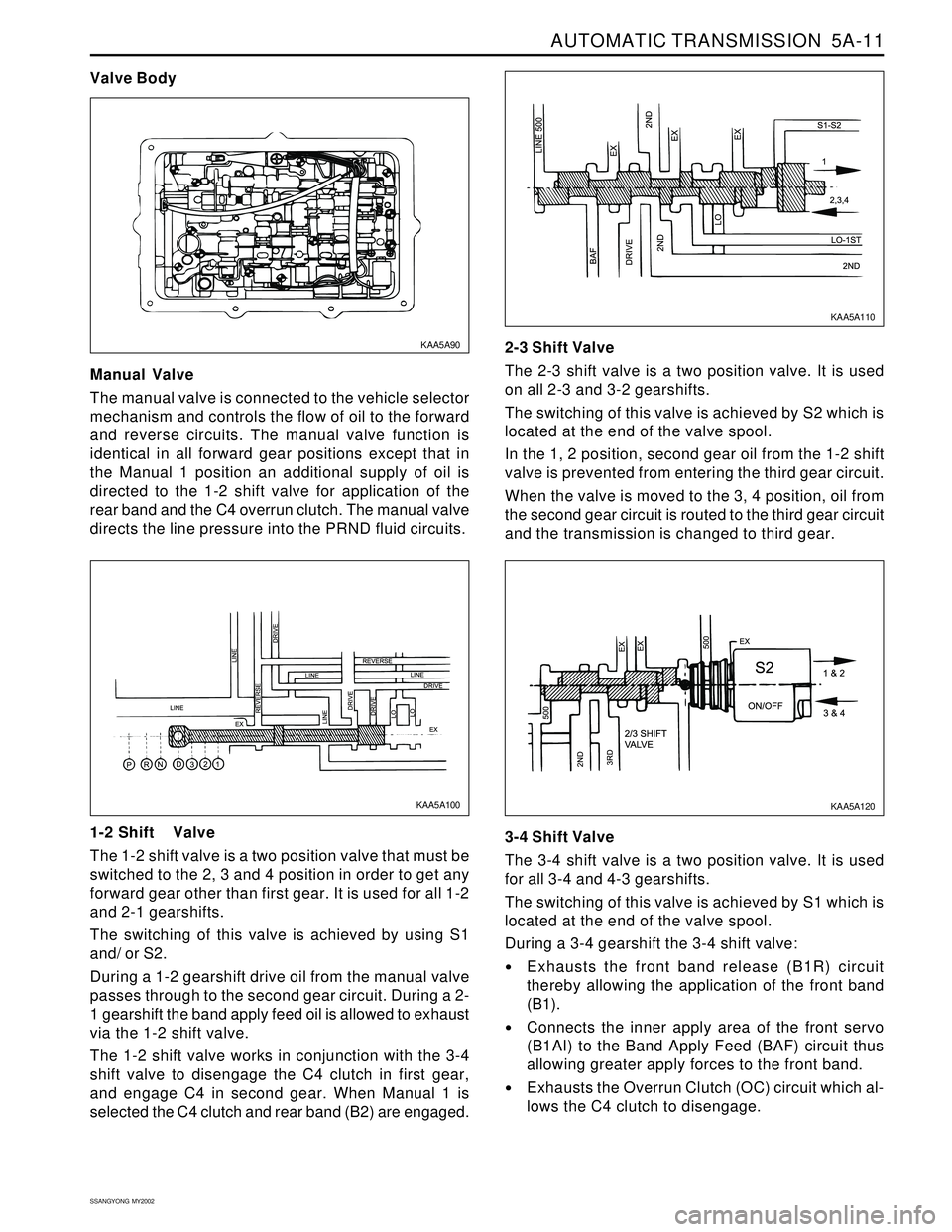
Manual Valve
The manual valve is connected to the vehicle selector
mechanism and controls the flow of oil to the forward
and reverse circuits. The manual valve function is
identical in all forward gear positions except that in
the Manual 1 position an additional supply of oil is
directed to the 1-2 shift valve for application of the
rear band and the C4 overrun clutch. The manual valve
directs the line pressure into the PRND fluid circuits.
Valve Body
1-2 Shift Valve
The 1-2 shift valve is a two position valve that must be
switched to the 2, 3 and 4 position in order to get any
forward gear other than first gear. It is used for all 1-2
and 2-1 gearshifts.
The switching of this valve is achieved by using S1
and/ or S2.
During a 1-2 gearshift drive oil from the manual valve
passes through to the second gear circuit. During a 2-
1 gearshift the band apply feed oil is allowed to exhaust
via the 1-2 shift valve.
The 1-2 shift valve works in conjunction with the 3-4
shift valve to disengage the C4 clutch in first gear,
and engage C4 in second gear. When Manual 1 is
selected the C4 clutch and rear band (B2) are engaged.2-3 Shift Valve
The 2-3 shift valve is a two position valve. It is used
on all 2-3 and 3-2 gearshifts.
The switching of this valve is achieved by S2 which is
located at the end of the valve spool.
In the 1, 2 position, second gear oil from the 1-2 shift
valve is prevented from entering the third gear circuit.
When the valve is moved to the 3, 4 position, oil from
the second gear circuit is routed to the third gear circuit
and the transmission is changed to third gear.
3-4 Shift Valve
The 3-4 shift valve is a two position valve. It is used
for all 3-4 and 4-3 gearshifts.
The switching of this valve is achieved by S1 which is
located at the end of the valve spool.
During a 3-4 gearshift the 3-4 shift valve:
Exhausts the front band release (B1R) circuit
thereby allowing the application of the front band
(B1).
Connects the inner apply area of the front servo
(B1AI) to the Band Apply Feed (BAF) circuit thus
allowing greater apply forces to the front band.
Exhausts the Overrun Clutch (OC) circuit which al-
lows the C4 clutch to disengage.
KAA5A100
KAA5A120 KAA5A90KAA5A110
Page 1106 of 2053
5A-12 AUTOMATIC TRANSMISSION
SSANGYONG MY2002
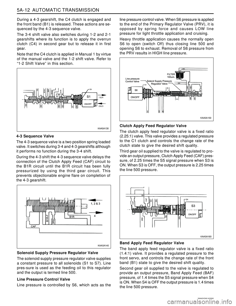
During a 4-3 gearshift, the C4 clutch is engaged and
the front band (B1) is released. These actions are se-
quenced by the 4-3 sequence valve.
The 3-4 shift valve also switches during 1-2 and 2-1
gearshifts where its function is to apply the overrun
clutch (C4) in second gear but to release it in first
gear.
Note that the C4 clutch is applied in Manual 1 by virtue
of the manual valve and the 1-2 shift valve. Refer to
“1-2 Shift Valve” in this section.
4-3 Sequence Valve
The 4-3 sequence valve is a two position spring loaded
valve. It switches during 3-4 and 4-3 gearshifts although
it performs no function during the 3-4 shift.
During the 4-3 shift the 4-3 sequence valve delays the
connection of the Clutch Apply Feed (CAF) circuit to
the B1R circuit until the B1R circuit has been fully
pressurized by using the third gear circuit. This
prevents objectionable engine flare on completion of
the 4-3 gearshift.
Solenoid Supply Pressure Regulator Valve
The solenoid supply pressure regulator valve supplies
a constant pressure to all solenoids (S1 to S7). Line
pres-sure is used as the feeding oil to this regulator
and the output is termed line 500.
Line Pressure Control Valve
Line pressure is controlled by S6, which acts as theline pressure control valve. When S6 pressure is applied
to the end of the Primary Regulator Valve (PRV), it is
opposed by spring force and causes LOW line
pressure for light throttle application and cruising.
Heavy throttle application causes the normally open
S6 to open (switch Off) thus closing line 500 and
opening S6 to exhaust. Removal of S6 pressure from
the PRV results in HIGH line pressure.
Clutch Apply Feed Regulator Valve
The clutch apply feed regulator valve is a fixed ratio
(2.25:1) valve. This valve provides a regulated pressure
to the C1 clutch and controls the change rate of the
clutch state to give the desired shift quality.
Third gear oil supplied to the valve is regulated to pro-
vide an output pressure, Clutch Apply Feed (CAF) pres-
sure, of 2.25 times the S5 signal pressure when S3 is
ON. When S3 is OFF, the output pressure is 2.25 times
the line 500 pressure.
Band Apply Feed Regulator Valve
The band apply feed regulator valve is a fixed ratio
(1.4:1) valve. It provides a regulated pressure to the
front servo, and controls the change rate of the front
band (B1) state to give the desired shift quality.
Second gear oil supplied to the valve is regulated to
provide an output pressure, Band Apply Feed (BAF)
pressure, of 1.4 times the S5 signal pressure when S4
is ON. When S4 is OFF the output pressure is 1.4 times
the line 500 pressure.
KAA5A160 KAA5A130
KAA5A150
KAA5A140
Page 1107 of 2053
AUTOMATIC TRANSMISSION 5A-13
SSANGYONG MY2002
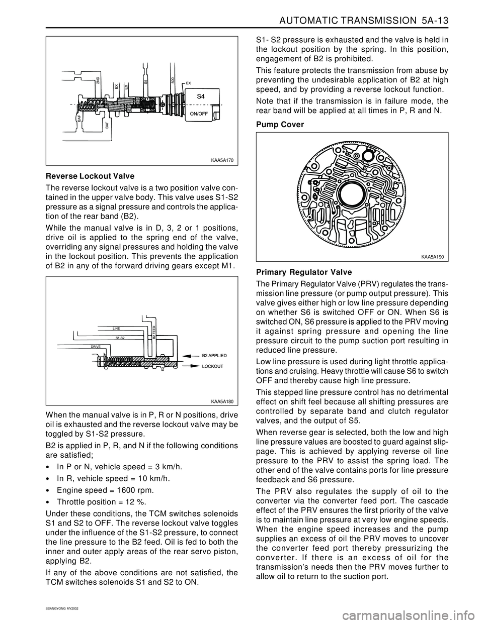
Reverse Lockout Valve
The reverse lockout valve is a two position valve con-
tained in the upper valve body. This valve uses S1-S2
pressure as a signal pressure and controls the applica-
tion of the rear band (B2).
While the manual valve is in D, 3, 2 or 1 positions,
drive oil is applied to the spring end of the valve,
overriding any signal pressures and holding the valve
in the lockout position. This prevents the application
of B2 in any of the forward driving gears except M1.S1- S2 pressure is exhausted and the valve is held in
the lockout position by the spring. In this position,
engagement of B2 is prohibited.
This feature protects the transmission from abuse by
preventing the undesirable application of B2 at high
speed, and by providing a reverse lockout function.
Note that if the transmission is in failure mode, the
rear band will be applied at all times in P, R and N.
Pump Cover
When the manual valve is in P, R or N positions, drive
oil is exhausted and the reverse lockout valve may be
toggled by S1-S2 pressure.
B2 is applied in P, R, and N if the following conditions
are satisfied;
In P or N, vehicle speed = 3 km/h.
In R, vehicle speed = 10 km/h.
Engine speed = 1600 rpm.
Throttle position = 12 %.
Under these conditions, the TCM switches solenoids
S1 and S2 to OFF. The reverse lockout valve toggles
under the influence of the S1-S2 pressure, to connect
the line pressure to the B2 feed. Oil is fed to both the
inner and outer apply areas of the rear servo piston,
applying B2.
If any of the above conditions are not satisfied, the
TCM switches solenoids S1 and S2 to ON.Primary Regulator Valve
The Primary Regulator Valve (PRV) regulates the trans-
mission line pressure (or pump output pressure). This
valve gives either high or low line pressure depending
on whether S6 is switched OFF or ON. When S6 is
switched ON, S6 pressure is applied to the PRV moving
it against spring pressure and opening the line
pressure circuit to the pump suction port resulting in
reduced line pressure.
Low line pressure is used during light throttle applica-
tions and cruising. Heavy throttle will cause S6 to switch
OFF and thereby cause high line pressure.
This stepped line pressure control has no detrimental
effect on shift feel because all shifting pressures are
controlled by separate band and clutch regulator
valves, and the output of S5.
When reverse gear is selected, both the low and high
line pressure values are boosted to guard against slip-
page. This is achieved by applying reverse oil line
pressure to the PRV to assist the spring load. The
other end of the valve contains ports for line pressure
feedback and S6 pressure.
The PRV also regulates the supply of oil to the
converter via the converter feed port. The cascade
effect of the PRV ensures the first priority of the valve
is to maintain line pressure at very low engine speeds.
When the engine speed increases and the pump
supplies an excess of oil the PRV moves to uncover
the converter feed port thereby pressurizing the
converter. If there is an excess of oil for the
transmission’s needs then the PRV moves further to
allow oil to return to the suction port.
KAA5A170
KAA5A180KAA5A190
Page 1108 of 2053

5A-14 AUTOMATIC TRANSMISSION
SSANGYONG MY2002
Converter Clutch Regulator Valve
The converter clutch regulator valve regulates the pres-
sure of the oil which applies the converter clutch. Input
oil from the line 500 circuit is regulated within the valve,
with the output pressure being variable according to
the signal pressure from the S5 circuit. Converter clutch
apply and release application is smoothed by
electronically varying the S5 circuit pressure.
Converter Clutch Control Valve
The converter clutch control valve is a two position
valve which applies or releases the converter clutch.
The switching of this valve is governed by the signal
pressure from S7.
When the valve is in the OFF or released position, con-
verter feed oil from the PRV is directed to the release
side of the converter clutch. After flowing through the
converter, oil returns to the converter clutch control
valve and is then directed to the oil cooler.
When the valve is in the ON or applied position, regu-
lated oil from the converter clutch regulator valve is
directed to the apply side of the converter clutch. This
oil remains within the converter because the converter
clutch piston is sealed against the flat friction surface
of the converter cover. To provide oil flow to the cooler
the converter clutch control valve directs converter feed
oil from the PRV directly to the cooler circuit.B1R Exhaust Valve
The B1R exhaust valve is a two position spring loaded
valve located in the transmission case directly adjacent
to the front servo. It permits the servo release oil to be
rapidly exhausted into the transmission case during
application of the front band (B1). This prevents the
need to force the oil back from the front servo through
the valve body and through the 3-4 shift valve. The
spring positions the valve to prevent oil entering the
release area of the servo until the B1R circuit oil
pressure reaches approximately 100 kPa.
POWER TRAIN SYSTEM
The Power Train System consists of;
A torque converter with single face lock-up clutch
Four multi-plate clutch assemblies
Two brake bands
Two one-way clutches
Planetary gear set
Parking mechanism
A conventional six pinion Ravigneaux compound plane-
tary gear set is used with overdrive (fourth gear) being
obtained by driving the carrier.
The cross-sectional arrangement is very modular in
nature.
Four main sub-assemblies are installed within the case
to complete the build. These subassemblies are;
KAA5A220KAA5A200
KAA5A210
KAA5A240
Page 1115 of 2053
AUTOMATIC TRANSMISSION 5A-21
SSANGYONG MY2002
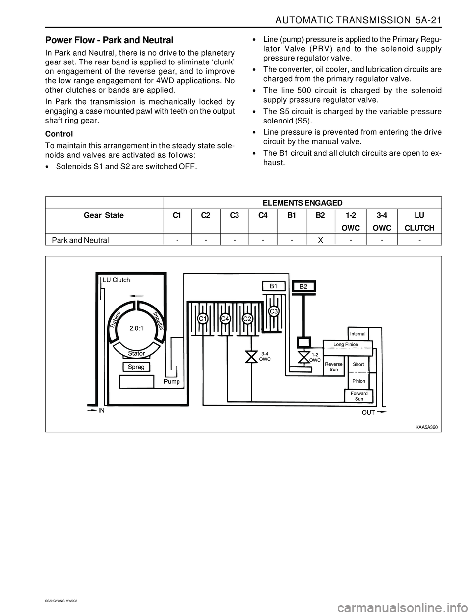
Power Flow - Park and Neutral
In Park and Neutral, there is no drive to the planetary
gear set. The rear band is applied to eliminate ‘clunk’
on engagement of the reverse gear, and to improve
the low range engagement for 4WD applications. No
other clutches or bands are applied.
In Park the transmission is mechanically locked by
engaging a case mounted pawl with teeth on the output
shaft ring gear.
Control
To maintain this arrangement in the steady state sole-
noids and valves are activated as follows:
Solenoids S1 and S2 are switched OFF.
Line (pump) pressure is applied to the Primary Regu-
lator Valve (PRV) and to the solenoid supply
pressure regulator valve.
The converter, oil cooler, and lubrication circuits are
charged from the primary regulator valve.
The line 500 circuit is charged by the solenoid
supply pressure regulator valve.
The S5 circuit is charged by the variable pressure
solenoid (S5).
Line pressure is prevented from entering the drive
circuit by the manual valve.
The B1 circuit and all clutch circuits are open to ex-
haust.
C1
-C2
-C3
-C4
-B1
-B2
X1-2
OWC
-3-4
OWC
-LU
CLUTCH
- Gear State
Park and Neutral
ELEMENTS ENGAGED
KAA5A320
Page 1117 of 2053
AUTOMATIC TRANSMISSION 5A-23
SSANGYONG MY2002
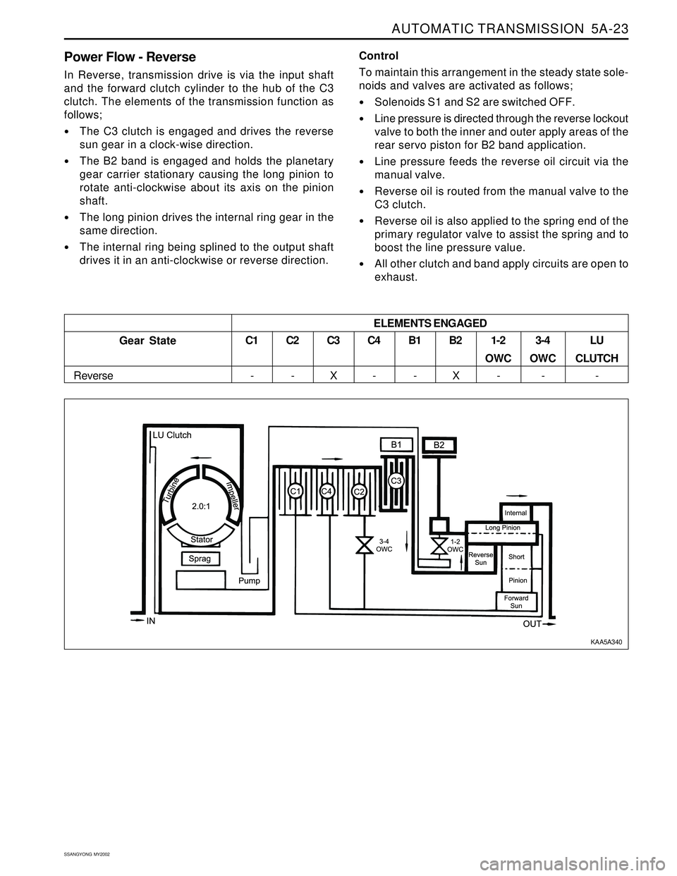
Power Flow - Reverse
In Reverse, transmission drive is via the input shaft
and the forward clutch cylinder to the hub of the C3
clutch. The elements of the transmission function as
follows;
The C3 clutch is engaged and drives the reverse
sun gear in a clock-wise direction.
The B2 band is engaged and holds the planetary
gear carrier stationary causing the long pinion to
rotate anti-clockwise about its axis on the pinion
shaft.
The long pinion drives the internal ring gear in the
same direction.
The internal ring being splined to the output shaft
drives it in an anti-clockwise or reverse direction.Control
To maintain this arrangement in the steady state sole-
noids and valves are activated as follows;
Solenoids S1 and S2 are switched OFF.
Line pressure is directed through the reverse lockout
valve to both the inner and outer apply areas of the
rear servo piston for B2 band application.
Line pressure feeds the reverse oil circuit via the
manual valve.
Reverse oil is routed from the manual valve to the
C3 clutch.
Reverse oil is also applied to the spring end of the
primary regulator valve to assist the spring and to
boost the line pressure value.
All other clutch and band apply circuits are open to
exhaust.
C3
X
Gear State
ReverseC1
-C2
-C4
-B1
-B2
X1-2
OWC
-3-4
OWC
-LU
CLUTCH
- ELEMENTS ENGAGED
KAA5A340