Page 612 of 2053

OM600 ENGINE MECHANICAL 1B3 -- 63
D AEW OO M Y_2000
TIMING CASE COVER
Preceding Work : Removal of the cooling fan
Rmoval of the V-- belt tensioning device
Removal of the vibration damper and hub
Removal of the generator
1 Bolt 10N∙m (89 lb-in) .....................
2 Cylinder Head Cover
3 Gasket Replace..........................
4 Socket Bolt 25N∙m (18 lb-ft) ................
5 Fuel Filter
6 Square Nut
7OilPan
8 Socket Bolt 10N∙m (89 lb-in) ...............
9 Bolt M6 : 10N∙m (89 lb-in) ................
M8 : 23N∙m (17 lb-ft)
10 Power Steering Pump
11 Bolt
12 Belt Pulley13 Bolt 32N∙m (24 lb-ft) ......................
14 Timing Case Cover
15 Bolt 23N∙m (17 lb-ft) ......................
16 Generator Bracket
17 Bolt 45N∙m (33 lb-ft) ......................
18 Bolt 25N∙m (18 lb-ft) ......................
19 Bolt 10N∙m(89lb-in) .....................
20 Closing Cover
21 Socket Bolt 23N∙m (17 lb-ft) ................
22 Guide Pulley
23 Bolt 9N∙m(80lb-in) .......................
24 Guide Pulley Bracket
25 Nut 23N∙m (17 lb-ft) .......................
Page 641 of 2053

1B3 -- 92 OM600 ENGINE MECHANICAL
D AEW OO M Y_2000
24. Insert the new connecting rod bearing shells into the
connecting rod and connecting rod bearing cap and
tighten the 12--sided stretch bolts (11).
Tightening Torque40 N∙m (30 lb-ft) + 90_
25. Measure inner diameter of connecting rod bearing.
26. Measure connecting rod bearing journal diameter
(K).
Notice
Refer to measurement of the crankshaft bearing
journal diameter.
27. Measure the radial clearance (L) of the connecting
rod bearing.
Example) Measured value ’J’ = 47.700mm
Measured value ’K’ = 47.653mm
——————————————
Clearance ’L’ = 0.047mm
Radial Clearance ’L’0.026 -- 0.068mm
Notice
If the clearance is out of standard, adjust the radial
clearance of connecting rod bearing by replacing the
connecting rod bearing shells.
28. Remove the connecting rod bearing cap.
29. Install the piston.
30. Rotate the crankshaft by hand and check whether it
rotates smoothly.
31. If the bearings are damaged,
-- replace the oil presser relief valve.
-- clean the oil pump and oil filter housing carefully
and replace the hose if necessary.
Notice
After assembling the engine, check the camshaft
timing, adjust the start of fuel injection and check the
TDC sensor bracket setting.
32. Fill oil and run the engine and then check the oil
pressure and oil level.
Notice
Install the original oil filter element and then change
the engine oil and oil filter element after 1,000 --
1,500km.
Page 718 of 2053
OM600 ENGINE MECHANICAL 1B3 -- 169
D AEW OO M Y_2000
OIL FILTER
1 Nut 25 N∙m (18 lb-ft) ......................
2 Oil Filter Cover...........................
3 O -- Ring Replace..........................
4 Oil Filter Element Replace If necessary.....
5 Oil Filter Housing6 Bolt (M8) 10 N∙m(89lb-in) ................
7 Oil Pressure Switch
8 Gasket
9Bolt 25N∙m (18 lb-ft) .....................
Page 719 of 2053
1B3 -- 170 OM600 ENGINE MECHANICAL
D AEW OO M Y_2000
Remeval & Installation Procedure
1. Remove the oil filter cover and then drain the oil.
2. Remove the oil pressure switch line.
3. Remove the oil filter housing.
4. Clean the sealing surface.
5. Installation should follow the removal procedure in
the reverse order.
Page 722 of 2053
OM600 ENGINE MECHANICAL 1B3 -- 173
D AEW OO M Y_2000
Oil Filter
a From Oil Pump
b To Main Oil Gallery
cToOilPan
Page 755 of 2053
OM600 ENGINE MECHANICAL 1B3 -- 3
D AEW OO M Y_2000
Cylinder Head
ApplicationNSmLb-- FtLb-- In
Prechamber Threaded Ring13096--
Cylinder Head Cover Bolt10--89
Fuel Injsction Pipe Nut1813--
Socket Bolt2518--
Fuel Filter Pipe Bolt2518--
Idle Pulley Bolt2317--
Damper Bolt2115--
Camshaft Bearing Cap Bolt2518--
Camshaft Sprocket Bolt25 / 90_18 / 90_--
Exhaust Pipe Bolt& Nut2518--
Chain Tensioner8059--
Injection Nozzle4030--
Intake Manifold Not2518--
Injection Nozzle Pipe Not1813--
Oil Dipstick Tube Bolt10--89
Screw Plug M18 x 155037--
Cam Support & Shaft
ApplicationNSmLb-- FtLb-- In
Stud Bolt12--106
Exhaust Manifold Not2518--
CamShaft Bearing Cap Bolt2518--
12-- Sided Bolt (M11)25 / 90_18 / 90_--
Timing Cover
ApplicationNSmLb-- FtLb-- In
Oil Pan Bolt -- Socket Bolt10--89
Oil Pan Bolt--M610--89
Oil Pan Bolt--M232317--
Belt Pulley Bolt3224--
Guide Pulley Bolt4--35
Guide Pulley Bracket Nut2317--
Chain Tensioner8059--
Tesioning Lever Bolt2317--
Page 866 of 2053
SSAMGYONG MY2002
3A-4 FRONT AXLE
AUTO-LOCKING HUB
1 Cap
2 Filter
3 Vacuum Diaphragm
4 Diaphragm Retainer
5 Piston
6 Bolt (M10)
7 Lock Washer
8 O-ring
9 Retaining Ring
10 Clutch Ring11 Body
12 Return Spring
13 Bearing
14 O-ring
15 Retaining Ring
16 Inner Drive Gear
17 Oil Seal
18 Oil Seal Race
19 Axle Retaining Ring
KAA3A020
Page 1256 of 2053

AUTOMATIC TRANSMISSION 5A-161
SSANGYONG MY2002
DISASSEMBLY PROCEDURE
Transmission
Tools Required
0555-336256Transmission Bench Cradle
0555-336257Pump Puller
Notice:
Remove the inhibitor switch before washing the
transmission in solvent or hot wash.
It is assumed that the transmission fluid has been
drained when the transmission was removed from
the vehicle and that the ‘special tools’ quoted are
available.
The transmission is dismantled in a modular fashion,
and the details of disassembly for each module are
given under the appropriate subject. Refer to Special
Tools Table in this chapter for details of all special
tools required when performing disassembly
procedures.
Technicians overhauling these transmissions will
also require a selection of good quality Torx bit
sockets, in particular numbers 30, 40 and 50, and
an 8 mm, 10 mm and 12 mm double hex socket.
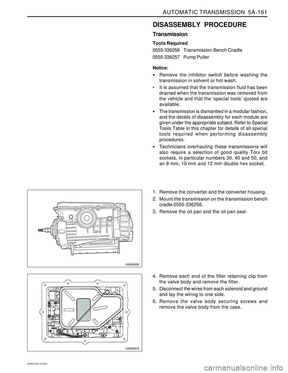
1. Remove the converter and the converter housing.
2. Mount the transmission on the transmission bench
cradle 0555-336256.
3. Remove the oil pan and the oil pan seal.
4. Remove each end of the filter retaining clip from
the valve body and remove the filter.
5. Disconnect the wires from each solenoid and ground
and lay the wiring to one side.
6. Remove the valve body securing screws and
remove the valve body from the case.
KAA5A500
KAA5A510