Page 386 of 2053
1B2 -- 98 M161 ENGINE MECHANICAL
D AEW OO M Y_2000
OIL NON-- RETURN VALVE
Preceding Work: Removal of timing gear case cover
1 Oil Non-- return Valve
Functions
The non -- return valve prevents the oil in the chain ten-
sioner from drying up. In other words, it stops oil-- return-
ing in order to prevent the oil in the chain tensioner from
getting dry. As a result, the chain tensioner can be acti-
vated with oil in itself.
Replacement Procedure
1. Remove the non--return valve using a pliers.
2. Insert new non-- return valve with hand.
Page 387 of 2053
M161 ENGINE MECHANICAL 1B2 -- 99
D AEW OO M Y_2000
OIL DIPSTICK GUIDE TUBE
1 Oil Dipstick Level Gauge
2 Oil Dipstick Guide Tube
3O--ring4 Bolt (M6 X 16, 1 piece)
9--11 NSm (80-- 97 lb-in) ....................
5 Clamp
Removal & Installation Procedure
1. Pull out the oil dipstick level gauge (1).
2. Unscrew the bolt (4) and remove the oil dipstick guide
tube (2).
Installation Notice
Tightening Torque
9--11NSm (80 -- 97 lb-in)
It is very hard to remove the oil dipstick guide tube
without special tool. If it is not necessary, do not re-
move the guide tube.
3. Installation should follow the removal procedure in
the reverse order.
4. Check for leaks by starting the engine.
Page 388 of 2053
1B2 -- 100 M161 ENGINE MECHANICAL
D AEW OO M Y_2000
UNIT REPAIR
CORE PLUGS IN CRANKCASE
Preceding Work: Draining of the coolant
1 Core Plug Replace.........................
Page 389 of 2053
M161 ENGINE MECHANICAL 1B2 -- 101
D AEW OO M Y_2000
Tools Required
102589001500 Drift
Replacement Procedure
1. Remove the intake and exhaust manifolds.
2. Pull back the core plug until the end of one side
comes out using the screw driver.
3. Pull out the plug carefully using a pliers.
4. Clean the sealing surface and apply Loctite 241.
5. Press in new plug using a drift.
Notice:Wait for about 45minutes before filling the cool-
ant so that the Loctite 241 hardens.
6. Warm up the engine and check the coolant for leaks.
Page 390 of 2053
1B2 -- 102 M161 ENGINE MECHANICAL
D AEW OO M Y_2000
CYLINDER BORE
Group Code Letter and Cylinder Bore Size
EngineGroup Code Letter of CylinderPiston Type to be UsedCylinder Bore Size (mm)
AAorXφ90.906 --φ90.912
XA, X or Bφ90.906 --φ90.912
E23BXorBφ90.912 --φ90.918
X+5X+5φ90.950 --φ90.968
X+10X+10φ91.000 --φ91.018
AAorXφ89.900 --φ90.906
XA, X or Bφ89.906 --φ89.912
E20BXorBφ89.912 --φ89.918
X+5X+5φ89.950 --φ89.968
X+10X+10φ90.000 --φ90.018
Page 391 of 2053

M161 ENGINE MECHANICAL 1B2 -- 103
D AEW OO M Y_2000
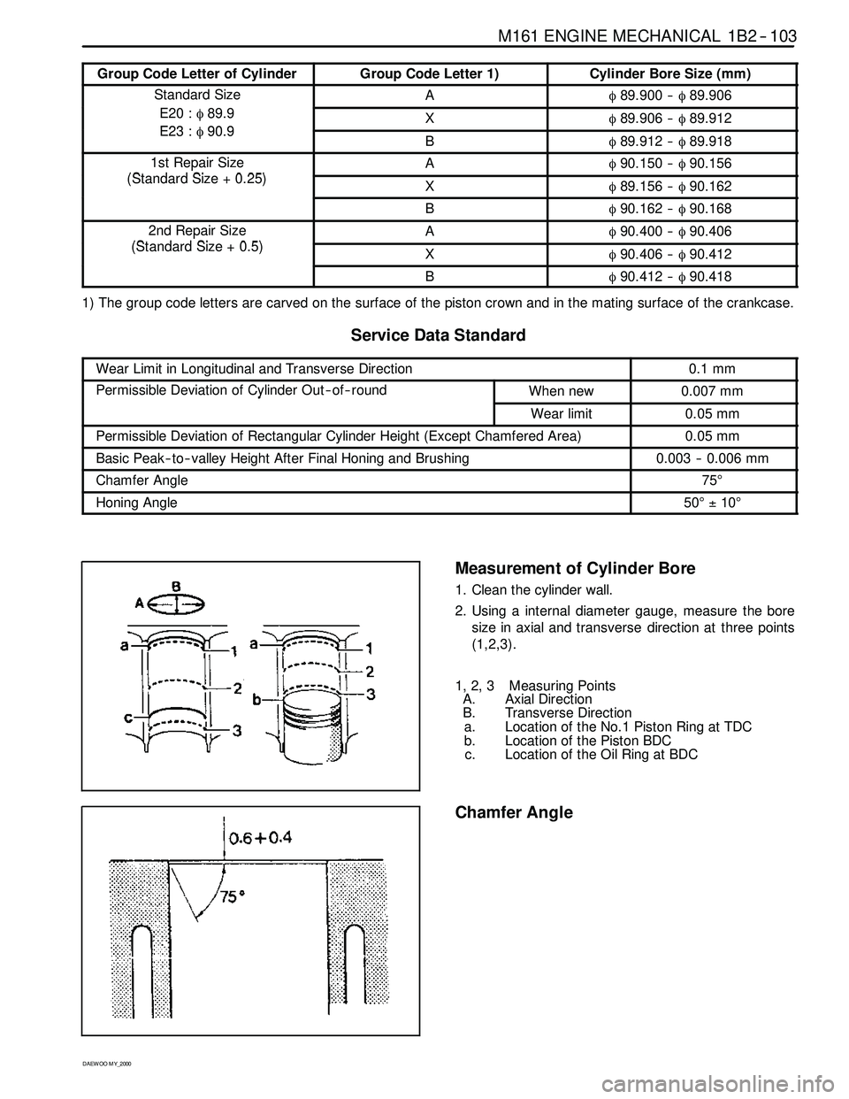
Group Code Letter of CylinderGroup Code Letter 1)Cylinder Bore Size (mm)
Standard SizeAφ89.900 --φ89.906
E20 :φ89.9
E23φ909Xφ89.906 --φ89.912E23 :φ90.9Bφ89.912 --φ89.918
1st Repair Size
(StddSi025)
Aφ90.150 --φ90.156p
(Standard Size + 0.25)Xφ89.156 --φ90.162
Bφ90.162 --φ90.168
2nd Repair Size
(StddSi05)
Aφ90.400 --φ90.406p
(Standard Size + 0.5)Xφ90.406 --φ90.412
Bφ90.412 --φ90.418
1) The group code letters are carved on the surface of the piston crown and in the mating surface of the crankcase.
ServiceDataStandard
Wear Limit in Longitudinal and Transverse Direction0.1 mm
Permissible Deviation of Cylinder Out -- of -- roundWhen new0.007 mmy
Wear limit0.05 mm
Permissible Deviation of Rectangular Cylinder Height (Except Chamfered Area)0.05 mm
Basic Peak -- to-- valley Height After Final Honing and Brushing0.003 -- 0.006 mm
Chamfer Angle75°
Honing Angle50°±10°
Measurement of Cylinder Bore
1. Clean the cylinder wall.
2. Using a internal diameter gauge, measure the bore
size in axial and transverse direction at three points
(1,2,3).
1, 2, 3 Measuring Points
A. Axial Direction
B. Transverse Direction
a. Location of the No.1 Piston Ring at TDC
b. Location of the Piston BDC
c. Location of the Oil Ring at BDC
Chamfer Angle
Page 392 of 2053
1B2 -- 104 M161 ENGINE MECHANICAL
D AEW OO M Y_2000
CRANKCASE MATING SURFACE
ServiceDataStandard
Height of The Crankcase ‘H’ (When new)289.35 -- 289.45 mm
Minimum Height After Milling289.05 mm
FlatnessCrankcase Upper Mating Surface0.03 mm
Crankcase Lower Mating Surface0.04 mm
Permissible Deviation of Parallelism of The
UtLMtiSf
Axial Direction0.1 mm
Upper to Lower Mating SurfaceTransverse Direction0.05 mm
Peak -- to-- valley HeightCrankcase Upper Mating Surface0.012 -- 0.009 mmyg
Crankcase Lower Mating Surface0.025 -- 0.020 mm
Page 393 of 2053
M161 ENGINE MECHANICAL 1B2 -- 105
D AEW OO M Y_2000
Chamfering Procedure
1. Chamfer angle : 75°
2. Polish the lower chamfered area evenly with a grinder
after finishing the chamfering with a suitable tool
(e.g., hand milling cutter).