Page 1268 of 2053
AUTOMATIC TRANSMISSION 5A-173
SSANGYONG MY2002
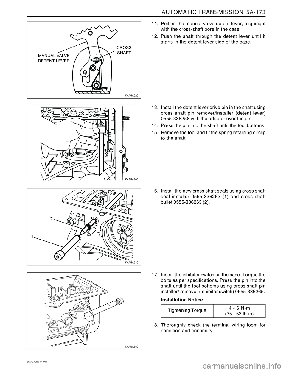
11. Poition the manual valve detent lever, aligning it
with the cross-shaft bore in the case.
12. Push the shaft through the detent lever until it
starts in the detent lever side of the case.
16. Install the new cross shaft seals using cross shaft
seal installer 0555-336262 (1) and cross shaft
bullet 0555-336263 (2).
17. Install the inhibitor switch on the case. Torque the
bolts as per specifications. Press the pin into the
shaft until the tool bottoms using cross shaft pin
installer/ remover (inhibitor switch) 0555-336265.
Installation Notice
18. Thoroughly check the terminal wiring loom for
condition and continuity. 13. Install the detent lever drive pin in the shaft using
cross shaft pin remover/installer (detent lever)
0555-336258 with the adaptor over the pin.
14. Press the pin into the shaft until the tool bottoms.
15. Remove the tool and fit the spring retaining circlip
to the shaft.
KAA5A920
KAA5A600
KAA5A930
KAA5A580
Tightening Torque4 - 6 Nm
(35 - 53 lb-in)
Page 1270 of 2053
AUTOMATIC TRANSMISSION 5A-175
SSANGYONG MY2002
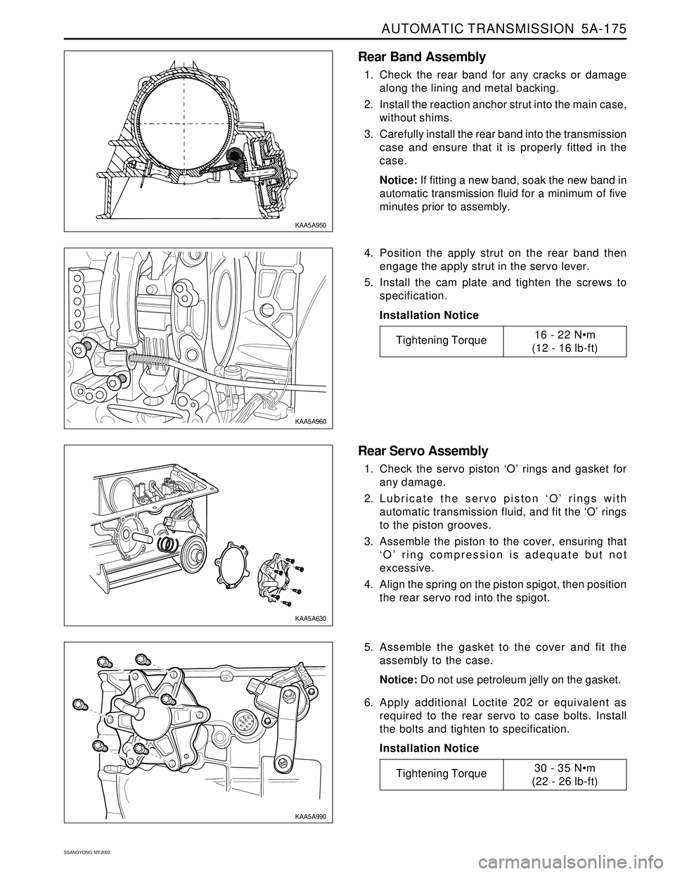
Rear Band Assembly
1. Check the rear band for any cracks or damage
along the lining and metal backing.
2. Install the reaction anchor strut into the main case,
without shims.
3. Carefully install the rear band into the transmission
case and ensure that it is properly fitted in the
case.
Notice: If fitting a new band, soak the new band in
automatic transmission fluid for a minimum of five
minutes prior to assembly.
4. Position the apply strut on the rear band then
engage the apply strut in the servo lever.
5. Install the cam plate and tighten the screws to
specification.
Installation Notice
Rear Servo Assembly
1. Check the servo piston ‘O’ rings and gasket for
any damage.
2. Lubricate the servo piston ‘O’ rings with
automatic transmission fluid, and fit the ‘O’ rings
to the piston grooves.
3. Assemble the piston to the cover, ensuring that
‘O’ ring compression is adequate but not
excessive.
4. Align the spring on the piston spigot, then position
the rear servo rod into the spigot.
5. Assemble the gasket to the cover and fit the
assembly to the case.
Notice: Do not use petroleum jelly on the gasket.
6. Apply additional Loctite 202 or equivalent as
required to the rear servo to case bolts. Install
the bolts and tighten to specification.
Installation Notice
KAA5A950
KAA5A960
KAA5A630
KAA5A990
Tightening Torque30 - 35 Nm
(22 - 26 lb-ft)
Tightening Torque16 - 22 Nm
(12 - 16 lb-ft)
Page 1271 of 2053
5A-176 AUTOMATIC TRANSMISSION
SSANGYONG MY2002
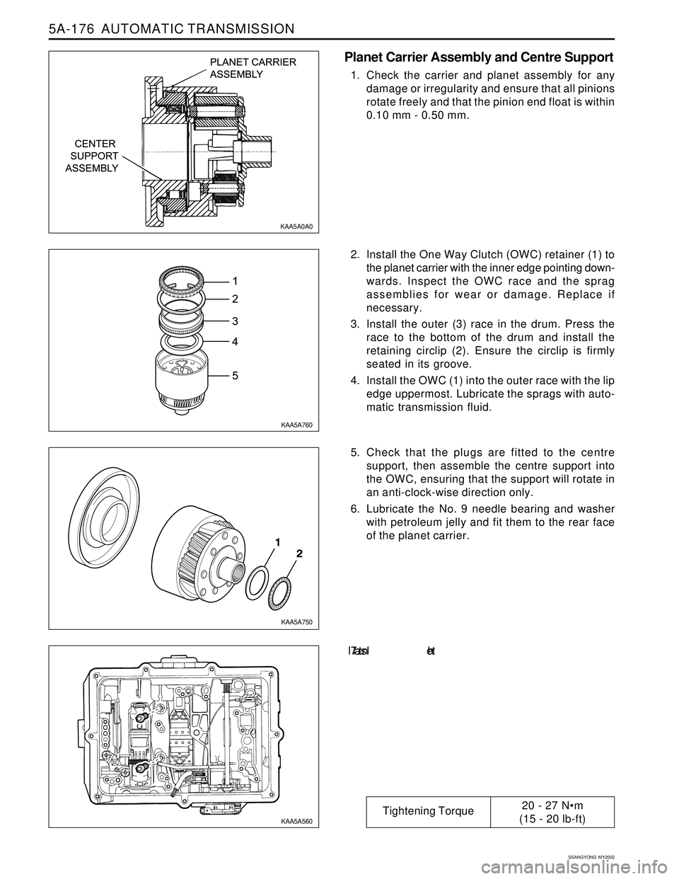
Planet Carrier Assembly and Centre Support
1. Check the carrier and planet assembly for any
damage or irregularity and ensure that all pinions
rotate freely and that the pinion end float is within
0.10 mm - 0.50 mm.
2. Install the One Way Clutch (OWC) retainer (1) to
the planet carrier with the inner edge pointing down-
wards. Inspect the OWC race and the sprag
assemblies for wear or damage. Replace if
necessary.
3. Install the outer (3) race in the drum. Press the
race to the bottom of the drum and install the
retaining circlip (2). Ensure the circlip is firmly
seated in its groove.
4. Install the OWC (1) into the outer race with the lip
edge uppermost. Lubricate the sprags with auto-
matic transmission fluid.
5. Check that the plugs are fitted to the centre
support, then assemble the centre support into
the OWC, ensuring that the support will rotate in
an anti-clock-wise direction only.
6. Lubricate the No. 9 needle bearing and washer
with petroleum jelly and fit them to the rear face
of the planet carrier.
7. In s t a l l th e
KAA5A0A0
KAA5A760
KAA5A750
KAA5A560
Tightening Torque20 - 27 Nm
(15 - 20 lb-ft)
Page 1272 of 2053
AUTOMATIC TRANSMISSION 5A-177
SSANGYONG MY2002
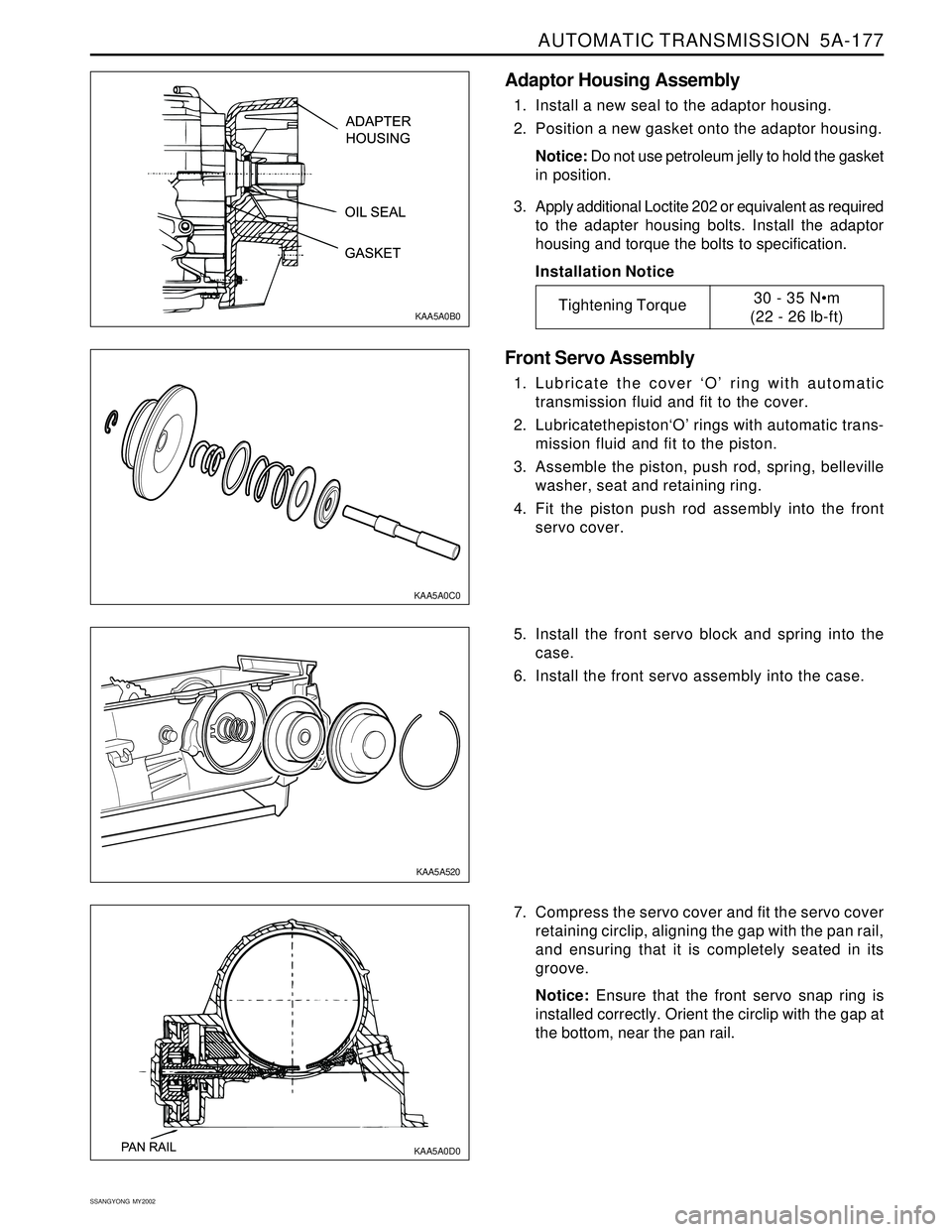
Adaptor Housing Assembly
1. Install a new seal to the adaptor housing.
2. Position a new gasket onto the adaptor housing.
Notice: Do not use petroleum jelly to hold the gasket
in position.
3. Apply additional Loctite 202 or equivalent as required
to the adapter housing bolts. Install the adaptor
housing and torque the bolts to specification.
Installation Notice
Front Servo Assembly
1. Lubricate the cover ‘O’ ring with automatic
transmission fluid and fit to the cover.
2. Lubricatethepiston‘O’ rings with automatic trans-
mission fluid and fit to the piston.
3. Assemble the piston, push rod, spring, belleville
washer, seat and retaining ring.
4. Fit the piston push rod assembly into the front
servo cover.
5. Install the front servo block and spring into the
case.
6. Install the front servo assembly into the case.
KAA5A0C0
KAA5A520 KAA5A0B0
Tightening Torque30 - 35 Nm
(22 - 26 lb-ft)
7. Compress the servo cover and fit the servo cover
retaining circlip, aligning the gap with the pan rail,
and ensuring that it is completely seated in its
groove.
Notice: Ensure that the front servo snap ring is
installed correctly. Orient the circlip with the gap at
the bottom, near the pan rail.
KAA5A0D0
Page 1285 of 2053
5A-190 AUTOMATIC TRANSMISSION
SSANGYONG MY2002
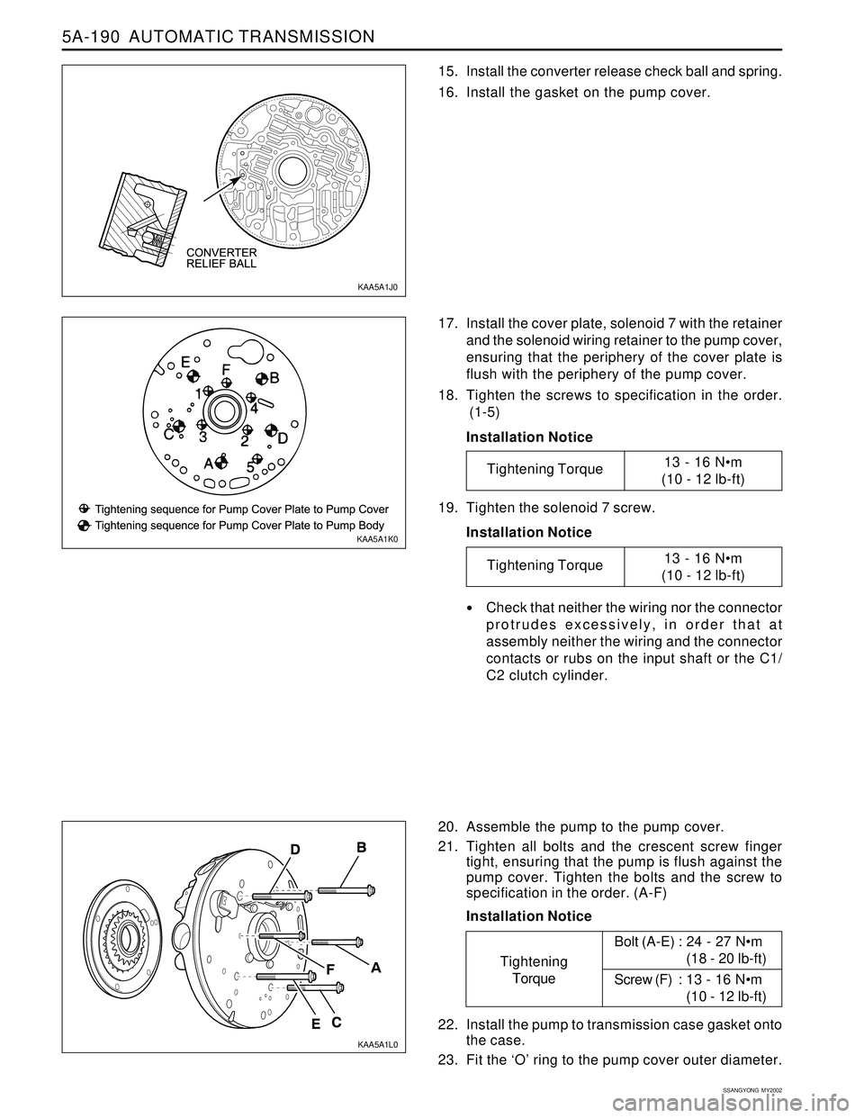
15. Install the converter release check ball and spring.
16. Install the gasket on the pump cover.
17. Install the cover plate, solenoid 7 with the retainer
and the solenoid wiring retainer to the pump cover,
ensuring that the periphery of the cover plate is
flush with the periphery of the pump cover.
18. Tighten the screws to specification in the order.
(1-5)
Installation Notice
20. Assemble the pump to the pump cover.
21. Tighten all bolts and the crescent screw finger
tight, ensuring that the pump is flush against the
pump cover. Tighten the bolts and the screw to
specification in the order. (A-F)
Installation Notice 19. Tighten the solenoid 7 screw.
Installation Notice
Check that neither the wiring nor the connector
protrudes excessively, in order that at
assembly neither the wiring and the connector
contacts or rubs on the input shaft or the C1/
C2 clutch cylinder.
22. Install the pump to transmission case gasket onto
the case.
23. Fit the ‘O’ ring to the pump cover outer diameter.
KAA5A1J0
KAA5A1K0
KAA5A1L0
Tightening Torque13 - 16 Nm
(10 - 12 lb-ft)
Tightening Torque13 - 16 Nm
(10 - 12 lb-ft)
Tightening
TorqueBolt (A-E) : 24 - 27 Nm
(18 - 20 lb-ft)
Screw (F) : 13 - 16 Nm
(10 - 12 lb-ft)
Page 1286 of 2053
AUTOMATIC TRANSMISSION 5A-191
SSANGYONG MY2002
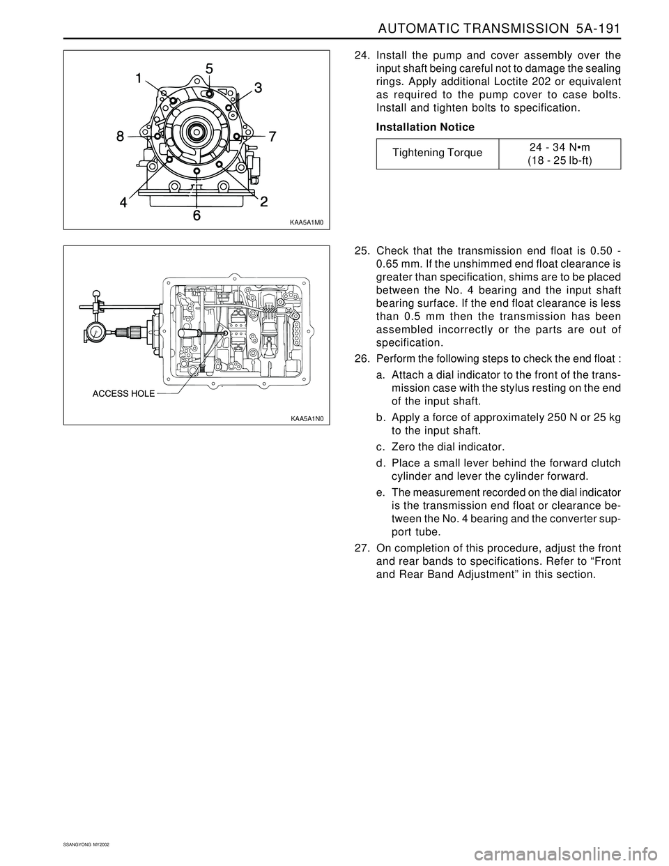
24. Install the pump and cover assembly over the
input shaft being careful not to damage the sealing
rings. Apply additional Loctite 202 or equivalent
as required to the pump cover to case bolts.
Install and tighten bolts to specification.
Installation Notice
KAA5A1M0
Tightening Torque24 - 34 Nm
(18 - 25 lb-ft)
25. Check that the transmission end float is 0.50 -
0.65 mm. If the unshimmed end float clearance is
greater than specification, shims are to be placed
between the No. 4 bearing and the input shaft
bearing surface. If the end float clearance is less
than 0.5 mm then the transmission has been
assembled incorrectly or the parts are out of
specification.
26. Perform the following steps to check the end float :
a. Attach a dial indicator to the front of the trans-
mission case with the stylus resting on the end
of the input shaft.
b. Apply a force of approximately 250 N or 25 kg
to the input shaft.
c. Zero the dial indicator.
d. Place a small lever behind the forward clutch
cylinder and lever the cylinder forward.
e. The measurement recorded on the dial indicator
is the transmission end float or clearance be-
tween the No. 4 bearing and the converter sup-
port tube.
27. On completion of this procedure, adjust the front
and rear bands to specifications. Refer to “Front
and Rear Band Adjustment” in this section.
KAA5A1N0
Page 1290 of 2053
AUTOMATIC TRANSMISSION 5A-195
SSANGYONG MY2002
19. Holding the separator plate to the upper valve
body to prevent the check balls from falling out,
install the upper valve body on the lower valve
body. Install all screws finger tight then tighten
the screws to specification in the prescribed
sequence.
Installation Notice
The wiring loom ground wire eyelet terminal is
secured beneath the solenoid 1 retainer. 16. Install the reverse lockout valve, spring, plug and
retaining plate. Ensure that the valve is correctly
oriented.
17. Position the five nylon ball checks in the upper
valve body.
18. Fit the upper valve body gasket. Install the
separator plate over the upper valve body.
KAA5A830 KAA5A840 KAA5A1V0
Tightening Torque11 - 16 Nm
(8 - 12 lb-ft)
20. Install solenoids 1, 2, 3, 4 and 6. Ensure the
solenoid is firmly secured by the retainer and that
the screw is tightened to specification.
Installation Notice
8 - 12 Nm
(71 - 106 lb-in)
Page 1291 of 2053
5A-196 AUTOMATIC TRANSMISSION
SSANGYONG MY2002
21. Install solenoid 5. Ensure that the solenoid is
pushed firmly into the valve body by the retainer
and that the screw is tightened to specification.
Installation Notice
22. Install the detent spring assembly (spring, support
plate and screw), ensuring that the screw is tight-
ened to specification. Check the spring for wear
or damage.
Installation Notice
23. Install the manual shift valve.
Notice: Be aware that the manual valve will fall out
of the valve body.
24. Align the valve body assembly on the
transmission case and install the manual valve
lever to manual valve link. Fit the long end of the
link to the manual valve first. Install the securing
bolts and tighten to specification in the specified
sequence.
Installation Notice
KAA5A1Y0 KAA5A1X0
KAA5A1Z0 KAA5A1W0
Tightening Torque8 - 12 Nm
(71 - 106 lb-in)
Tightening Torque20 - 22 Nm
(15 - 16 lb-ft)
Tightening Torque8 - 13 Nm
(71 - 115 lb-in)