Page 1292 of 2053

AUTOMATIC TRANSMISSION 5A-197
SSANGYONG MY2002
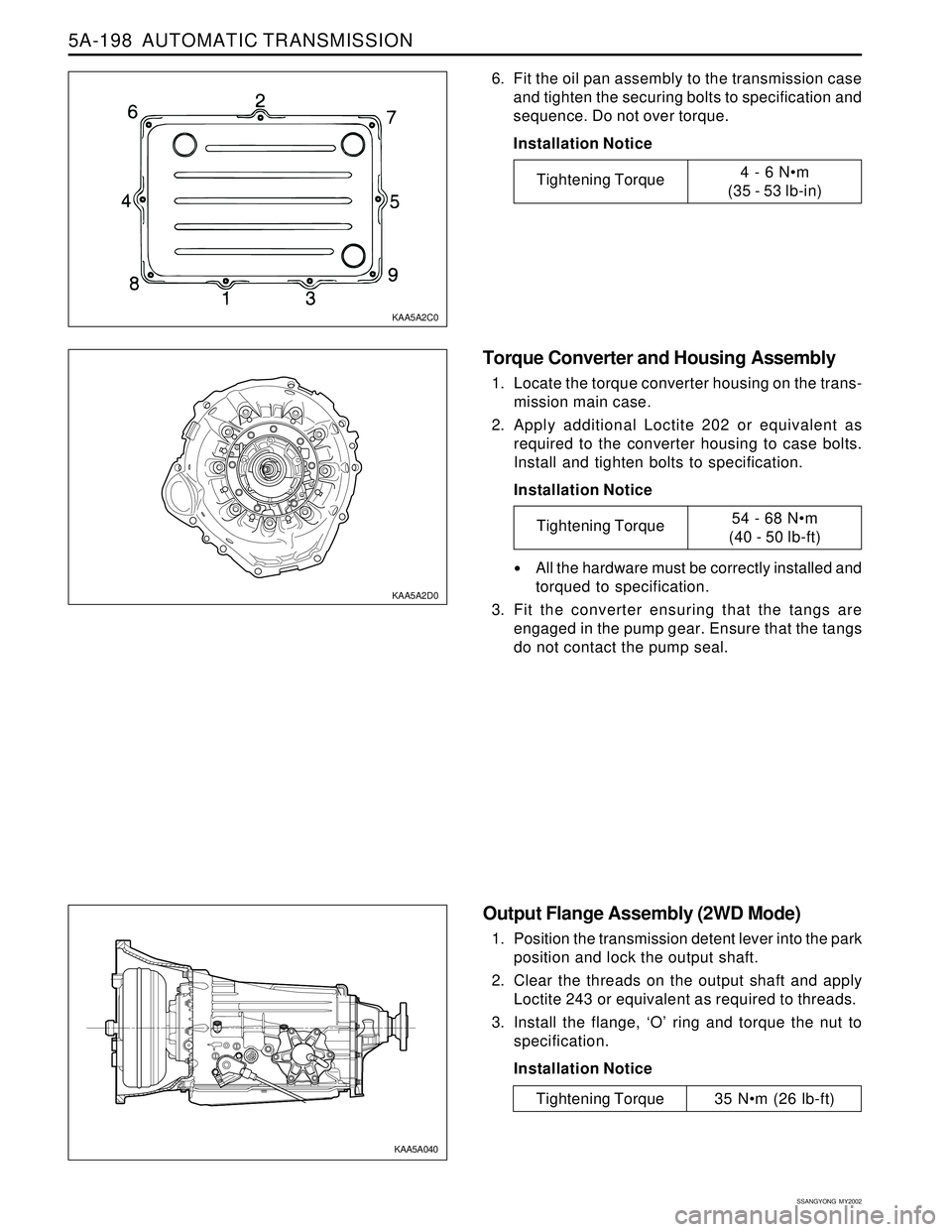
2. Carefully assemble the oil filter to the valve body.
The spigot must not lean on one side while being
fitted.
3. Secure the oil filter assembly with the retainer.
4. Check that the magnet is located in the dimple in
the corner of the oil pan.
5. Assemble the gasket on the pan lip. The gasket
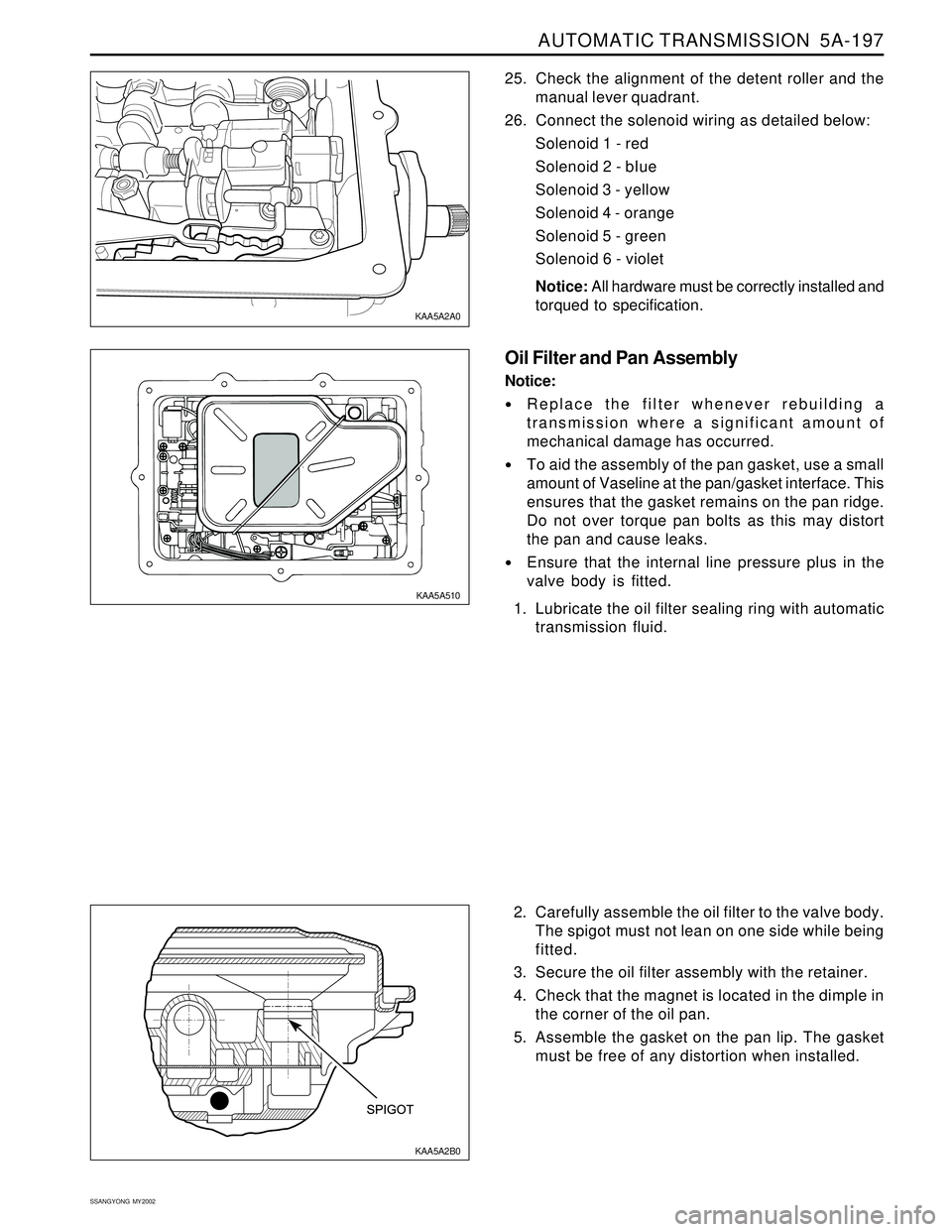
must be free of any distortion when installed. 25. Check the alignment of the detent roller and the
manual lever quadrant.
26. Connect the solenoid wiring as detailed below:
Solenoid 1 - red
Solenoid 2 - bIue
Solenoid 3 - yellow
Solenoid 4 - orange
Solenoid 5 - green
Solenoid 6 - violet
Notice: All hardware must be correctly installed and
torqued to specification.
Oil Filter and Pan Assembly
Notice:
Replace the filter whenever rebuilding a
transmission where a significant amount of
mechanical damage has occurred.
To aid the assembly of the pan gasket, use a small
amount of Vaseline at the pan/gasket interface. This
ensures that the gasket remains on the pan ridge.
Do not over torque pan bolts as this may distort
the pan and cause leaks.
Ensure that the internal line pressure plus in the
valve body is fitted.
1. Lubricate the oil filter sealing ring with automatic
transmission fluid.
KAA5A2B0 KAA5A2A0
KAA5A510
Page 1293 of 2053

5A-198 AUTOMATIC TRANSMISSION
SSANGYONG MY2002
Torque Converter and Housing Assembly
1. Locate the torque converter housing on the trans-
mission main case.
2. Apply additional Loctite 202 or equivalent as
required to the converter housing to case bolts.
Install and tighten bolts to specification.
Installation Notice
All the hardware must be correctly installed and
torqued to specification.
3. Fit the converter ensuring that the tangs are
engaged in the pump gear. Ensure that the tangs
do not contact the pump seal.
Output Flange Assembly (2WD Mode)
1. Position the transmission detent lever into the park
position and lock the output shaft.
2. Clear the threads on the output shaft and apply
Loctite 243 or equivalent as required to threads.
3. Install the flange, ‘O’ ring and torque the nut to
specification.
Installation Notice
6. Fit the oil pan assembly to the transmission case
and tighten the securing bolts to specification and
sequence. Do not over torque.
Installation Notice
KAA5A2C0
KAA5A2D0
KAA5A040
Tightening Torque4 - 6 Nm
(35 - 53 lb-in)
Tightening Torque54 - 68 Nm
(40 - 50 lb-ft)
Tightening Torque 35 Nm (26 lb-ft)
Page 1298 of 2053
AUTOMATIC TRANSMISSION 5A-203
SSANGYONG MY2002
SPECIFICATIONS
GENERAL SPECIFICATION
Model Specifications
Clutch Pack Details Model Part Numbers And Applications
Descriprtion
260 mm (10.2 in.)
2.0 : 1
2.741 : 1
1.508 : 1
1.000 : 1
0.708 : 1
2.429 : 1
Castrol TQ95
9.0 Liters (approx.)
4.5 Liters (approx.)
0.50 - 0.65 mm (0.020 - 0.026 in.)
0.10 - 0.50 mm (0.004 - 0.020 in.)Application
Torque Converter
Mean Diameter of Fluid Circuit Description
Maximum Torque Multiplication
Gear Ratios
First
Second
Third
Fourth
Reverse
Lubricant
Type
Capacity
Dry System
Service Refill
Gear Train End Float
Gear Set Pinion End Float
Transmission
0574-000013
0574-000012Torque Converter
179K
150K Engine Version
E23
E32 SYMC P/NO
36100-05442
36100-05432
C1
Composition
Steel
C2
Composition
Steel
C3
Composition
Steel
C4
Composition
Steel
0574-000012 (13)
5 (4)
5 (6)
5 (4)
4 (5)
4 (3)
4 (5)
3 (3)
4 (4)
Page 1300 of 2053

AUTOMATIC TRANSMISSION 5A-205
SSANGYONG MY2002
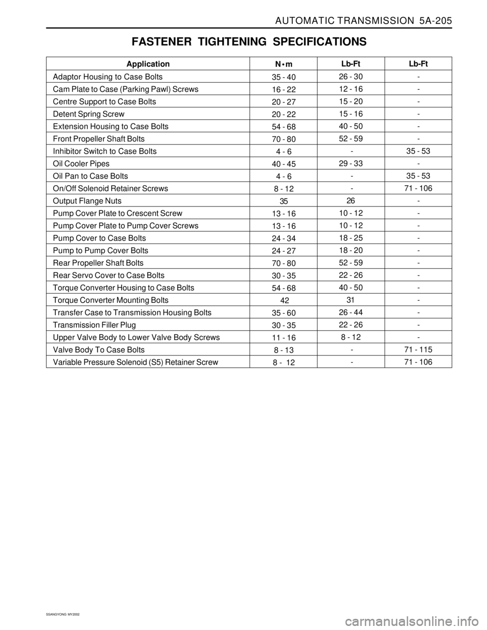
FASTENER TIGHTENING SPECIFICATIONS
N•m
35 - 40
16 - 22
20 - 27
20 - 22
54 - 68
70 - 80
4 - 6
40 - 45
4 - 6
8 - 12
35
13 - 16
13 - 16
24 - 34
24 - 27
70 - 80
30 - 35
54 - 68
42
35 - 60
30 - 35
11 - 16
8 - 13
8 - 12Lb-Ft
26 - 30
12 - 16
15 - 20
15 - 16
40 - 50
52 - 59
-
29 - 33
-
-
26
10 - 12
10 - 12
18 - 25
18 - 20
52 - 59
22 - 26
40 - 50
31
26 - 44
22 - 26
8 - 12
-
- Application
Adaptor Housing to Case Bolts
Cam Plate to Case (Parking Pawl) Screws
Centre Support to Case Bolts
Detent Spring Screw
Extension Housing to Case Bolts
Front Propeller Shaft Bolts
Inhibitor Switch to Case Bolts
Oil Cooler Pipes
Oil Pan to Case Bolts
On/Off Solenoid Retainer Screws
Output Flange Nuts
Pump Cover Plate to Crescent Screw
Pump Cover Plate to Pump Cover Screws
Pump Cover to Case Bolts
Pump to Pump Cover Bolts
Rear Propeller Shaft Bolts
Rear Servo Cover to Case Bolts
Torque Converter Housing to Case Bolts
Torque Converter Mounting Bolts
Transfer Case to Transmission Housing Bolts
Transmission Filler Plug
Upper Valve Body to Lower Valve Body Screws
Valve Body To Case Bolts
Variable Pressure Solenoid (S5) Retainer ScrewLb-Ft
-
-
-
-
-
-
35 - 53
-
35 - 53
71 - 106
-
-
-
-
-
-
-
-
-
-
-
-
71 - 115
71 - 106
Page 1330 of 2053

SSANGYONG MY2002
5B-22 MANUAL TRANSMISSION
62 - 93 Nm
(45 - 69 lb-ft)
21 - 35 Nm
(15 - 26 lb-ft)
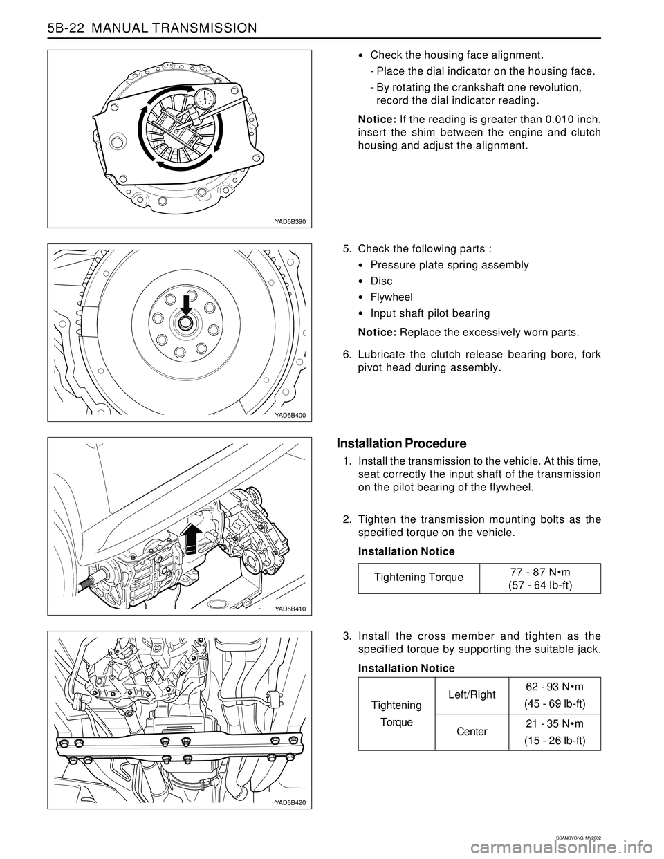
Check the housing face alignment.
- Place the dial indicator on the housing face.
- By rotating the crankshaft one revolution,
record the dial indicator reading.
Notice: If the reading is greater than 0.010 inch,
insert the shim between the engine and clutch
housing and adjust the alignment.
5. Check the following parts :
Pressure plate spring assembly
Disc
Flywheel
Input shaft pilot bearing
Notice: Replace the excessively worn parts.
6. Lubricate the clutch release bearing bore, fork
pivot head during assembly.
Installation Procedure
1. Install the transmission to the vehicle. At this time,
seat correctly the input shaft of the transmission
on the pilot bearing of the flywheel.
2. Tighten the transmission mounting bolts as the
specified torque on the vehicle.
Installation Notice
YAD5B390
YAD5B400
YAD5B410
YAD5B420
Tightening Torque77 - 87 Nm
(57 - 64 lb-ft)
3. Install the cross member and tighten as the
specified torque by supporting the suitable jack.
Installation Notice
Tightening
TorqueLeft/Right
Center
Page 1331 of 2053
MANUAL TRANSMISSION 5B-23
SSANGYONG MY2002
4. Install the front and rear propeller shafts to the
transmission.
Installation Notice
5. Connect the cable, the harness and the bleeder.
6. Install the back lamp switch.
7. Install the speedometer cable.
YAD5B430
YAD5B440
YAD5B450
YAD5B310
81 - 89 Nm
(60 - 66 lb-ft)
70 - 90 Nm
(52 - 66 lb-ft)
Tightening
TorqueFront
Rear
8. Charge the approved oil in the transmission
housing and tighten the drain plug and the filler
plug.
Installation Notice
Oil25 Nm (18 lb-ft)
25 Nm (18 lb-ft)
Tightening
TorqueFiller Plug
Drain Plug
Spec.
Capacity
3.4L
2.0L
4WD
2WDATF Dexron II
Page 1338 of 2053
SSANGYONG MY2002
5B-30 MANUAL TRANSMISSION
Assembly Procedure
1. Using a hydraulic press and a supporting tool,
press the counter shaft rear bearing into the case.
Be sure that the supporting tool inside of the case
should support the counter shaft.
YAD5B710
YAD5B720
YAD5B740
YAD5B730
2. Without the shim, install the retainer and counter
shaft rear bearing outer race. Tighten the 4 retainer
bolts.
Installation Notice
3. Place a dial indicator on the case and measure
counter shaft end play by moving up and down.
4. Select a shim which is the same thickness as the
indicator rearing (up to 0.004 inch) and assemble
it.
5. When the end play is correctly adjusted, remove
the counter shaft rear bearing retainer and outer
race.
6. Using a pin punch and rubber hammer, install the
reverse idler shaft, gear and O-ring.
Tightening Torque 20 Nm (15 lb-ft)
Page 1339 of 2053
MANUAL TRANSMISSION 5B-31
SSANGYONG MY2002
7. Install the counter shaft rear bearing outer race,
shim and retainer.
Installation Notice
Notice: Using a punch and hammer, bend the lock
tabs on the retainer.
YAD5B750
YAD5B760
YAD5B770
8. Install the following parts :
Install the main shaft into case.
Install the main shaft rear bearing outer race
into the rear of the case.
Install the 4th speed blocking ring onto the front
of the main shaft.
Install the input shaft onto the front of the main
shaft.
Install the input bearing retainer without shim
onto the front of the case.
Using a torque wrench, tighten the 4 bolts.
Installation Notice
9. Install the 5th speed drive gear and blocking ring
on the counter shaft.
10. Install the 5th synchronizer and rail/fork.
11. Install the 5th synchronizer snap ring and oiling
funnel.
Tightening Torque 20 Nm (15 lb-ft)
Tightening Torque 20 Nm (15 lb-ft)