1997 SSANGYONG KORANDO reservoir
[x] Cancel search: reservoirPage 923 of 2053

HYDRAULIC BRAKES 4A-3
SSANGYONG MY2002
DIAGNOSTIC INFORMATION AND PROCEDURES
BRAKE SYSTEM TESTING
Brakes should be tested on a dry, clean, reasonably
smooth and level roadway. A true test of brake perfor-
mance cannot be made if the roadway is wet, greasy,
or covered with loose dirt which can cause tires not to
grip the road unequally. Testing also will be inaccurate
on a crowned roadway because the wheels tend to
bounce.
Test the brakes at different vehicle speeds with both
light-and heavy-pedal pressure; however, avoid locking
the brakes and sliding the tires. Locked brakes and
slid-ing tires do not indicate brake efficiency since
heavily braked but turning wheels will stop the vehicle
in less distance than locked brakes. More tire-to-road
friction is present with a heavily braked, turning tire
than with a sliding tire.
Because of the high deceleration capability, a firmer
pedal may be felt at higher deceleration levels.
There are three major external conditions that affect
brake performance:
•Tires having unequal contact and grip of the road
will cause unequal braking. Tires must be equally
inflated, and the tread pattern of the right and the
left tires must be approximately equal.
Unequal loading of the vehicle can affect the brake
performance since the most heavily loaded wheels
require more braking power, and thus more braking
effort, than the others.
Misalignment of the wheels, particularly conditions
of excessive camber and caster, will cause the
brakes to pull to one side.
To check for brake fluid leaks, hold constant foot pres-
sure on the pedal with the engine running at idle and
the shift lever in NEUTRAL. If the pedal gradually falls
away with the constant pressure, the hydraulic system
may be leaking. Perform a visual check to confirm any
suspected leaks.
Check the master cylinder fluid level. While a slight
drop in the reservoir level results from normal lining
wear, an abnormally low level indicates a leak in the
system. The hydraulic system may be leaking either
internally or externally. Refer to the procedure below
to check the master cylinder. The system may appear
to pass this test while still having a slight leak. If the
fluid level is normal, check the vacuum booster pushrod
length. If an incorrect pushrod length is found, adjust
or replace the rod.Check the master cylinder using the following proce
dure:
Check for a cracked master cylinder casting or a
brake fluid leak around the master cylinder. Leaks
are indicated only if there is at least one drop of
fluid. A damp condition is not abnormal.
Check for a binding pedal linkage and for an
incorrect pushrod length. If both of these parts are
in satisfactory condition, disassemble the master
cylinder and check for an elongated or swollen
primary cylinder or piston seals. If swollen seals
are found, substandard or contaminated brake fluid
should be suspected. If contaminated brake fluid
is found, all the components should be
disassembled and cleaned, and all the rubber
components should be replaced. All of the pipes
must also be flushed.
Improper brake fluid, or mineral oil or water in the fluid,
may cause the brake fluid to boil or cause deterioration
of the rubber components. If the primary piston cups in
the master cylinder are swollen, the rubber parts have
deteriorated.
If deterioration of the rubber is evident, disassemble
all the hydraulic parts and wash the parts with alcohol.
Dry these parts with compressed air before reassembly
to keep the alcohol out of the system. Replace all the
rubber parts in the system, including the hoses. When
working on the brake mechanisms, check for fluid on
the linings. If excessive fluid is found, replace the
linings.
If the master cylinder piston seals are in satisfactory
condition, check for leaks or excessive heat conditions.
If these conditions are not found, drain the fluid, flush
the master cylinder with brake fluid, refill the master
cylinder, and bleed the system.
BRAKE HOSE INSPECTION
The hydraulic brake hoses should be inspected at least
twice a year. The brake hose assembly should be
checked for road hazard damage, cracks, chafing of
the outer cover, and for leaks or blisters. Inspect the
hoses for proper routing and mounting. A brake hose
that rubs on a suspension component will wear and
eventually fail. A light and a mirror may be needed for
an adequate inspection. If any of the above conditions
are observed on the brake hose, adjust or replace the
hose as necessary.
Page 925 of 2053

HYDRAULIC BRAKES 4A-5
SSANGYONG MY2002
Value(s)
-
-
-
-
-
-
-
-
-
-
-
-
-
-
BRAKE WARNING LAMP DIAGNOSIS
Step
1
2
3
4
5
6
7
8
9
10
11
12
13
14Action
Start the engine and leave it running.
Does the BRAKE warning lamp stay on?
With the engine running, release the parking brake.
Is the BRAKE warning lamp off?
Check the brake fluid level.
Is the fluid level OK?
1. Fill the brake fluid reservoir with clean DOT-3
hydraulic fluid.
2. Check the cap on the fluid reservoir.
3. Start the engine and leave it running.
Is the BRAKE warning lamp on?
Disconnect the wiring harness connector from the
brake fluid level switch.
Is the BRAKE warning lamp on?
Replace the brake fluid lever switch.
Is the repair complete?
1. Connect the brake fluid level switch.
2. Disconnect the parking brake lever switch.
3. Start the engine and leave it running.
Is the BRAKE warning lamp on?
Replace the parking brake lever switch.
Is the repair complete?
1. Connect the parking brake lever switch.
2. Disconnect the STICS (Super Time and Alarm
Integrated System).
3. Start the engine and leave it running.
Is the BRAKE warning lamp on?
Replace the STICS.
Is the repair complete?
Repair the short circuit in the instrument wiring
harness between terminal D10 of the instrument
cluster and ground.
Is the repair complete?
1. Disconnect the electrical connector from the fluid
level switch.
2. Connect a jumper wire between ground and
terminal 1 of the fluid level switch harness
connector.
Does the BRAKE warning lamp turn on?
1. Disconnect the electrical connector from the fluid
level switch.
2. Connect a jump wire between terminals 1 and 2
of the fluid level switch harness connector.
Does the BRAKE warning lamp turn on?
1. Replace the brake fluid level switch.
2 The switch can be removed and replaced without
draining the brake fluid from the reservoir.
Is the repair complete?Yes
Go To Step 2
System OK
Go To Step 5
Go To Step 5
Go To Step 7
System OK
Go To Step 9
System OK
Go To Step 11
System OK
System OK
Go To Step 13
Go To Step 14
System OKNO
Go To Step 12
Go To Step 3
Go To Step 4
System OK
Go To Step 6
-
Go To Step 8
-
Go To Step 10
-
-
Go To Step 15
Go To Step 15
-
Page 930 of 2053
SSAMGYONG MY2002
4A-10 HYDRAULIC BRAKES
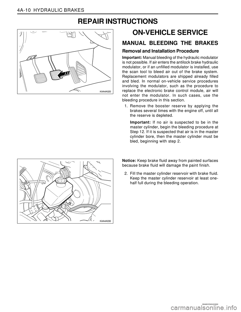
KAA4A020
KAA4A030
Notice: Keep brake fluid away from painted surfaces
because brake fluid will damage the paint finish.
2. Fill the master cylinder reservoir with brake fluid.
Keep the master cylinder reservoir at least one-
half full during the bleeding operation.
ON-VEHICLE SERVICE
MANUAL BLEEDING THE BRAKES
Removal and Installation Procedure
Important: Manual bleeding of the hydraulic modulator
is not possible. If air enters the antilock brake hydraulic
modulator, or if an unfilled modulator is installed, use
the scan tool to bleed air out of the brake system.
Replacement modulators are shipped already filled
and bled. In normal on-vehicle service procedures
involving the modulator, such as the procedure to
replace the electronic brake control module, air will
not enter the modulator. In such cases, use the
bleeding procedure in this section.
1. Remove the booster reserve by applying the
brakes several times with the engine off, until all
the reserve is depleted.
Important: If no air is suspected to be in the
master cylinder, begin the bleeding procedure at
Step 12. If it is suspected that air is in the master
cylinder bore, then the master cylinder must be
bled, beginning with step 2.
REPAIR INSTRUCTIONS
Page 937 of 2053

Description and Operation...................................4B-2
General Description.............................................4B-2
Component Locator.............................................4B-3
Repair Instructions................................................4B-4
On-Vehicle Service.................................................4B-4Brake Oil Level Switch .........................................4B-4
Brake Fluid Reservoir ...........................................4B-4
Master Cylinder...................................................4B-5
Specifications.......................................................4B-8
Fastener Tightening Specifications.......................4B-8
SECTION 4B
MASTER CYLINDER
TABLE OF CONTENTS
Page 938 of 2053

SSANGYONG MY2002
4B-2 MASTER CYLINDER
DESCRIPTION AND OPERATION
GENERAL DESCRIPTION
The master cylinder is designed for use in a parallel
split system. One front and one parallel to rear brakes
are served by the primary piston. The opposite front
and rear brakes are served by the secondary piston.
The master cylinder incorporates the functions of the
standard dual master cylinder, plus a low fluid level
indicator. The brake fluid level switch is attached under
the body of the plastic brake master cylinder reservoir.
Notice: Do not use lubricated shop air on the brake
parts, because oil will damage the rubber components.Important:•Replace all the components included in the repair
kits used to service the master cylinder.
Lubricate the rubber parts with clean brake fluid to
ease assembly.
If any hydraulic component is removed or discon-
nected, it may be necessary to bleed all or part of
the brake system. Refer to Section 4F, Antilock
Brake System and Traction Control System.
The torque values specified are for dry, unlubricated
fasteners.
Perform all service operations on a clean bench,
free from all traces of mineral oil.
Page 939 of 2053

MASTER CYLINDER 4B-3
SSANGYONG MY2002
KAA4B070
COMPONENT LOCATOR
1 Brake Fluid Level Switch Connector
2 Brake Fluid Reservoir
3 Power Booster4 Brake Lines
(Master Cylinder-to-Hydraulic Modulator)
5 Master Cylinder
Page 940 of 2053

SSANGYONG MY2002
4B-4 MASTER CYLINDER
ON-VEHICLE SERVICE
BRAKE OIL LEVEL SWITCH
Removal and Installation Procedure
1. Disconnect the brake fluid level switch connector.
2. Disconnect the switch wiring connector.
3. Disconnect the switch from the brake oil tank.
4. Installation should follow the removal procedure
in the reverse order.
REPAIR INSTRUCTIONS
BRAKE FLUID RESERVOIR
Removal and Installation Procedure
Important: Remove the brake fluid reservoir only when
it must be replaced because of damage or leaks.
1. Disconnect the brake fluid level switch connector.
2. Drain the brake fluid.
KAA4B020
KAA4B020
KAA4B050
3. Remove the brake fluid reservoir fromthe master
cylinder body by tilting the reservoir and pulling
it up-ward.
Page 941 of 2053

MASTER CYLINDER 4B-5
SSANGYONG MY2002
KAA4B060
4. Remove and discard the brake fluid reservoir seals
from the master cylinder body.
Installation Notice:
Lubricate the new brake fluid reservoir seals with
clean brake fluid.
After the installation, bleed the brake system.
Refer to Section 4F, Antilock Brake System and
Traction Control System.
5. Installation should follow the removal procedure
in the reverse order.
YAD4A340
YAD4A350
YAD4A360
3. Remove the master cylinder.
Retain the master cylinder in the vice and
remove the retainer ring from the master cylinder
using the snap ring plier. 2. Loosen the mounting nut of the master cylinder
and remove the master cylinder from the power
booster.
MASTER CYLINDER
Removal Procedure
1. Disconnect the brake lines from the master
cylinder.
Notice: The brake fluid may damage paintwork, if
spillage onto paintwork, wash with cold water
immediately.