1997 SSANGYONG KORANDO check transmission fluid
[x] Cancel search: check transmission fluidPage 1197 of 2053
5A-102 AUTOMATIC TRANSMISSION
SSANGYONG MY2002
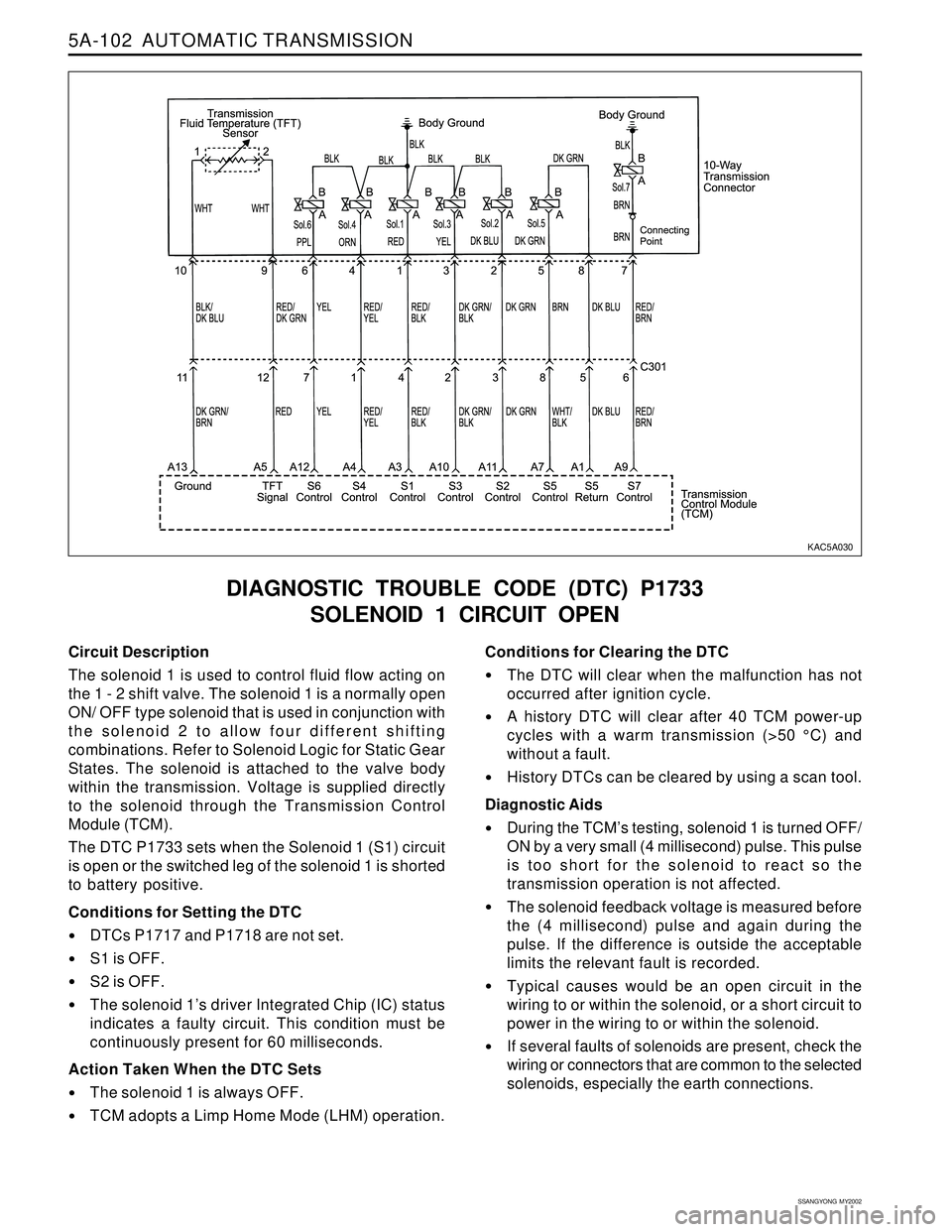
Circuit Description
The solenoid 1 is used to control fluid flow acting on
the 1 - 2 shift valve. The solenoid 1 is a normally open
ON/ OFF type solenoid that is used in conjunction with
the solenoid 2 to allow four different shifting
combinations. Refer to Solenoid Logic for Static Gear
States. The solenoid is attached to the valve body
within the transmission. Voltage is supplied directly
to the solenoid through the Transmission Control
Module (TCM).
The DTC P1733 sets when the Solenoid 1 (S1) circuit
is open or the switched leg of the solenoid 1 is shorted
to battery positive.
Conditions for Setting the DTC
DTCs P1717 and P1718 are not set.
S1 is OFF.
S2 is OFF.
The solenoid 1’s driver Integrated Chip (IC) status
indicates a faulty circuit. This condition must be
continuously present for 60 milliseconds.
Action Taken When the DTC Sets
The solenoid 1 is always OFF.
TCM adopts a Limp Home Mode (LHM) operation.
DIAGNOSTIC TROUBLE CODE (DTC) P1733
SOLENOID 1 CIRCUIT OPEN
Conditions for Clearing the DTC
The DTC will clear when the malfunction has not
occurred after ignition cycle.
A history DTC will clear after 40 TCM power-up
cycles with a warm transmission (>50 °C) and
without a fault.
History DTCs can be cleared by using a scan tool.
Diagnostic Aids
During the TCM’s testing, solenoid 1 is turned OFF/
ON by a very small (4 millisecond) pulse. This pulse
is too short for the solenoid to react so the
transmission operation is not affected.
The solenoid feedback voltage is measured before
the (4 millisecond) pulse and again during the
pulse. If the difference is outside the acceptable
limits the relevant fault is recorded.
Typical causes would be an open circuit in the
wiring to or within the solenoid, or a short circuit to
power in the wiring to or within the solenoid.
If several faults of solenoids are present, check the
wiring or connectors that are common to the selected
solenoids, especially the earth connections.
KAC5A030
Page 1201 of 2053
5A-106 AUTOMATIC TRANSMISSION
SSANGYONG MY2002
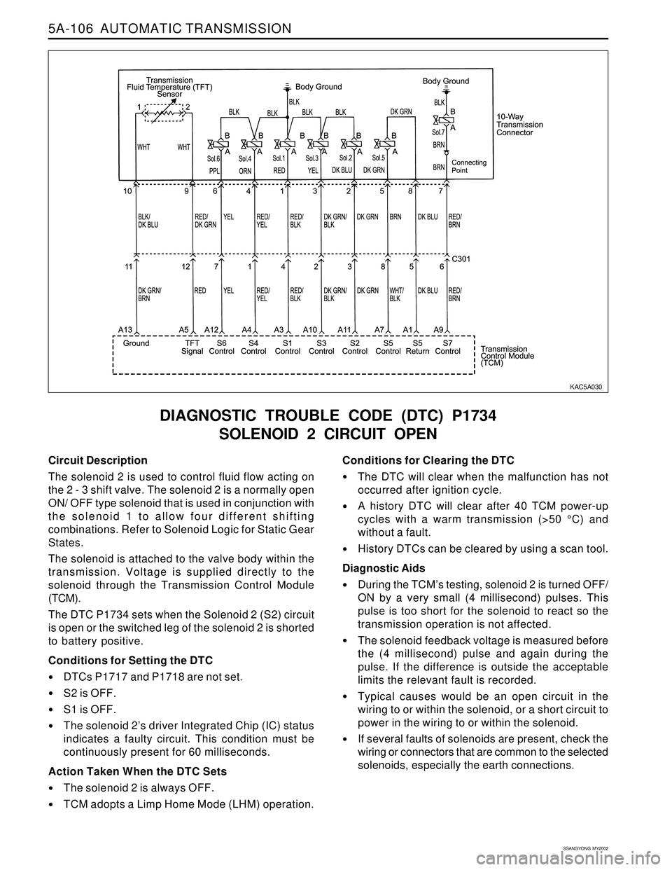
Circuit Description
The solenoid 2 is used to control fluid flow acting on
the 2 - 3 shift valve. The solenoid 2 is a normally open
ON/ OFF type solenoid that is used in conjunction with
the solenoid 1 to allow four different shifting
combinations. Refer to Solenoid Logic for Static Gear
States.
The solenoid is attached to the valve body within the
transmission. Voltage is supplied directly to the
solenoid through the Transmission Control Module
(TCM).
The DTC P1734 sets when the Solenoid 2 (S2) circuit
is open or the switched leg of the solenoid 2 is shorted
to battery positive.
Conditions for Setting the DTC
DTCs P1717 and P1718 are not set.
S2 is OFF.
S1 is OFF.
The solenoid 2’s driver Integrated Chip (IC) status
indicates a faulty circuit. This condition must be
continuously present for 60 milliseconds.
Action Taken When the DTC Sets
The solenoid 2 is always OFF.
TCM adopts a Limp Home Mode (LHM) operation.
DIAGNOSTIC TROUBLE CODE (DTC) P1734
SOLENOID 2 CIRCUIT OPEN
Conditions for Clearing the DTC
The DTC will clear when the malfunction has not
occurred after ignition cycle.
A history DTC will clear after 40 TCM power-up
cycles with a warm transmission (>50 °C) and
without a fault.
History DTCs can be cleared by using a scan tool.
Diagnostic Aids
During the TCM’s testing, solenoid 2 is turned OFF/
ON by a very small (4 millisecond) pulses. This
pulse is too short for the solenoid to react so the
transmission operation is not affected.
The solenoid feedback voltage is measured before
the (4 millisecond) pulse and again during the
pulse. If the difference is outside the acceptable
limits the relevant fault is recorded.
Typical causes would be an open circuit in the
wiring to or within the solenoid, or a short circuit to
power in the wiring to or within the solenoid.
If several faults of solenoids are present, check the
wiring or connectors that are common to the selected
solenoids, especially the earth connections.
KAC5A030
Page 1225 of 2053
5A-130 AUTOMATIC TRANSMISSION
SSANGYONG MY2002
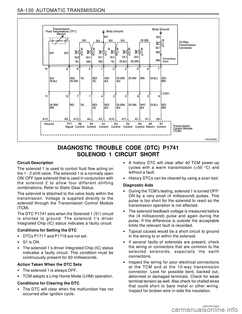
Circuit Description
The solenoid 1 is used to control fluid flow acting on
the 1 - 2 shift valve. The solenoid 1 is a normally open
ON/ OFF type solenoid that is used in conjunction with
the solenoid 2 to allow four different shifting
combinations. Refer to Static Gear Status.
The solenoid is attached to the valve body within the
transmission. Voltage is supplied directly to the
solenoid through the Transmission Control Module
(TCM).
The DTC P1741 sets when the Solenoid 1 (S1) circuit
is shorted to ground. The solenoid 1’s driver
Integrated Chip (IC) status indicates a faulty circuit.
Conditions for Setting the DTC
DTCs P1717 and P1718 are not set.
S1 is ON.
The solenoid 1’s driver Integrated Chip (IC) status
indicates a faulty circuit. This condition must be
continuously present for 60 milliseconds.
Action Taken When the DTC Sets
The solenoid 1 is always OFF.
TCM adopts a Limp Home Mode (LHM) operation.
Conditions for Clearing the DTC
The DTC will clear when the malfunction has not
occurred after ignition cycle.
DIAGNOSTIC TROUBLE CODE (DTC) P1741
SOLENOID 1 CIRCUIT SHORT
A history DTC will clear after 40 TCM power-up
cycles with a warm transmission (>50 °C) and
without a fault.
History DTCs can be cleared by using a scan tool.
Diagnostic Aids
During the TCM’s testing, solenoid 1 is turned OFF/
ON by a very small (4 millisecond) pulses. This
pulse is too short for the solenoid to react so the
transmission operation is not affected.
The solenoid feedback voltage is measured before
the (4 millisecond) pulse and again during the
pulse. If the difference is outside the acceptable
limits the relevant fault is recorded.
Typical causes would be a short circuit to ground
in the wiring to or within the solenoid.
If several faults of solenoids are present, check
the wiring or connectors that are common to the
selected solenoids, especially the earth
connections.
Inspect the wiring for poor electrical connections
at the TCM and at the 10-way transmission
connector. Look for possible bent, backed out,
deformed or damaged terminals. Check for weak
terminal tension as well. Also check for chafed wires
that could short to bare metal or other wiring.
Inspect for broken wire in-side the insulation.
KAC5A030
Page 1229 of 2053
5A-134 AUTOMATIC TRANSMISSION
SSANGYONG MY2002
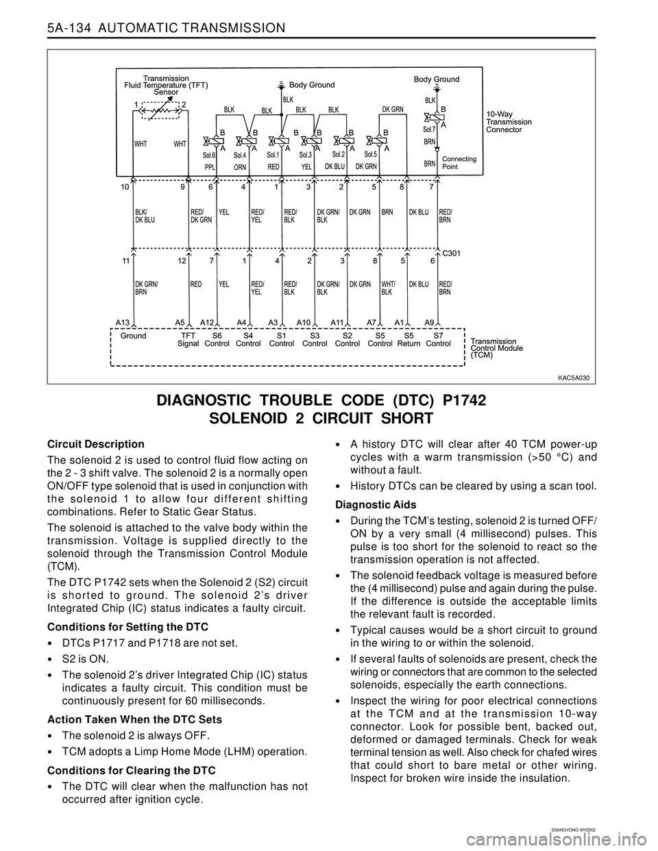
Circuit Description
The solenoid 2 is used to control fluid flow acting on
the 2 - 3 shift valve. The solenoid 2 is a normally open
ON/OFF type solenoid that is used in conjunction with
the solenoid 1 to allow four different shifting
combinations. Refer to Static Gear Status.
The solenoid is attached to the valve body within the
transmission. Voltage is supplied directly to the
solenoid through the Transmission Control Module
(TCM).
The DTC P1742 sets when the Solenoid 2 (S2) circuit
is shorted to ground. The solenoid 2’s driver
Integrated Chip (IC) status indicates a faulty circuit.
Conditions for Setting the DTC
DTCs P1717 and P1718 are not set.
S2 is ON.
The solenoid 2’s driver Integrated Chip (IC) status
indicates a faulty circuit. This condition must be
continuously present for 60 milliseconds.
Action Taken When the DTC Sets
The solenoid 2 is always OFF.
TCM adopts a Limp Home Mode (LHM) operation.
Conditions for Clearing the DTC
The DTC will clear when the malfunction has not
occurred after ignition cycle.
DIAGNOSTIC TROUBLE CODE (DTC) P1742
SOLENOID 2 CIRCUIT SHORT
A history DTC will clear after 40 TCM power-up
cycles with a warm transmission (>50 °C) and
without a fault.
History DTCs can be cleared by using a scan tool.
Diagnostic Aids
During the TCM’s testing, solenoid 2 is turned OFF/
ON by a very small (4 millisecond) pulses. This
pulse is too short for the solenoid to react so the
transmission operation is not affected.
The solenoid feedback voltage is measured before
the (4 millisecond) pulse and again during the pulse.
If the difference is outside the acceptable limits
the relevant fault is recorded.
Typical causes would be a short circuit to ground
in the wiring to or within the solenoid.
If several faults of solenoids are present, check the
wiring or connectors that are common to the selected
solenoids, especially the earth connections.
Inspect the wiring for poor electrical connections
at the TCM and at the transmission 10-way
connector. Look for possible bent, backed out,
deformed or damaged terminals. Check for weak
terminal tension as well. Also check for chafed wires
that could short to bare metal or other wiring.
Inspect for broken wire inside the insulation.
KAC5A030
Page 1255 of 2053
5A-160 AUTOMATIC TRANSMISSION
SSANGYONG MY2002
UNIT REPAIR
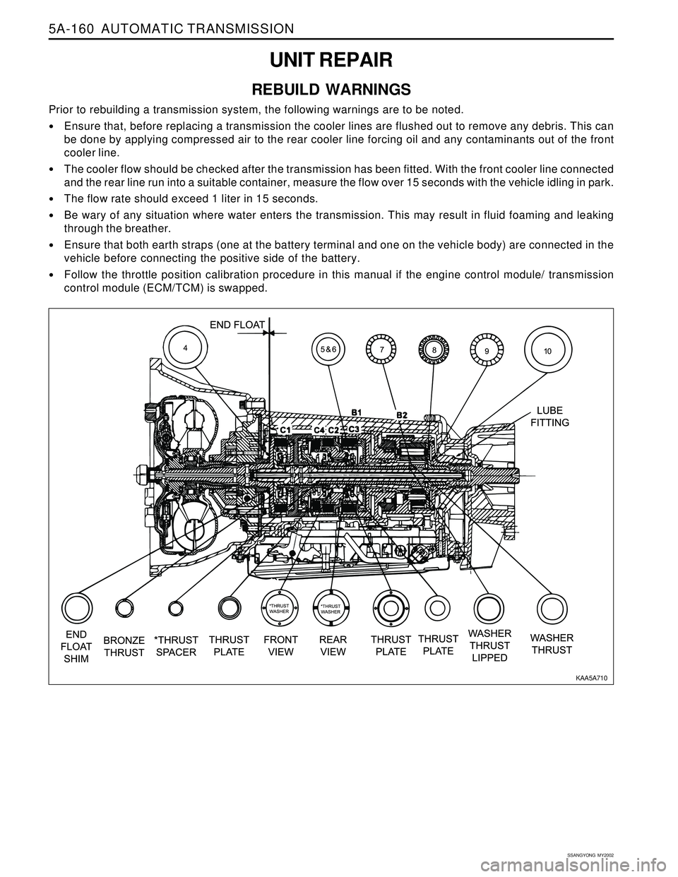
REBUILD WARNINGS
Prior to rebuilding a transmission system, the following warnings are to be noted.
Ensure that, before replacing a transmission the cooler lines are flushed out to remove any debris. This can
be done by applying compressed air to the rear cooler line forcing oil and any contaminants out of the front
cooler line.
The cooler flow should be checked after the transmission has been fitted. With the front cooler line connected
and the rear line run into a suitable container, measure the flow over 15 seconds with the vehicle idling in park.
The flow rate should exceed 1 liter in 15 seconds.
Be wary of any situation where water enters the transmission. This may result in fluid foaming and leaking
through the breather.
Ensure that both earth straps (one at the battery terminal and one on the vehicle body) are connected in the
vehicle before connecting the positive side of the battery.
Follow the throttle position calibration procedure in this manual if the engine control module/ transmission
control module (ECM/TCM) is swapped.
KAA5A710
Page 1269 of 2053
5A-174 AUTOMATIC TRANSMISSION
SSANGYONG MY2002
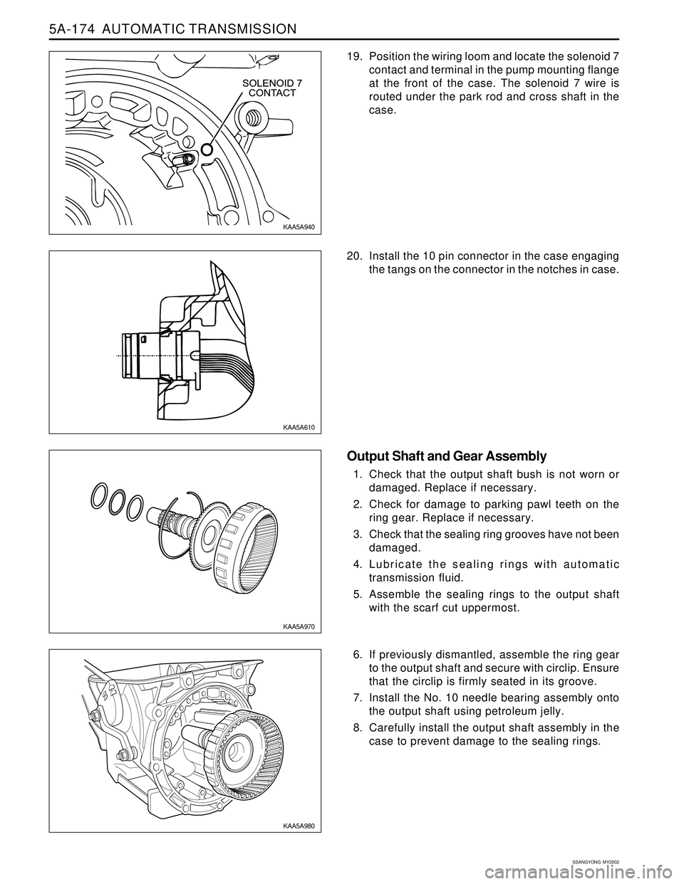
19. Position the wiring loom and locate the solenoid 7
contact and terminal in the pump mounting flange
at the front of the case. The solenoid 7 wire is
routed under the park rod and cross shaft in the
case.
20. Install the 10 pin connector in the case engaging
the tangs on the connector in the notches in case.
Output Shaft and Gear Assembly
1. Check that the output shaft bush is not worn or
damaged. Replace if necessary.
2. Check for damage to parking pawl teeth on the
ring gear. Replace if necessary.
3. Check that the sealing ring grooves have not been
damaged.
4. Lubricate the sealing rings with automatic
transmission fluid.
5. Assemble the sealing rings to the output shaft
with the scarf cut uppermost.
6. If previously dismantled, assemble the ring gear
to the output shaft and secure with circlip. Ensure
that the circlip is firmly seated in its groove.
7. Install the No. 10 needle bearing assembly onto
the output shaft using petroleum jelly.
8. Carefully install the output shaft assembly in the
case to prevent damage to the sealing rings.
KAA5A940
KAA5A610
KAA5A970
KAA5A980
Page 1270 of 2053
AUTOMATIC TRANSMISSION 5A-175
SSANGYONG MY2002
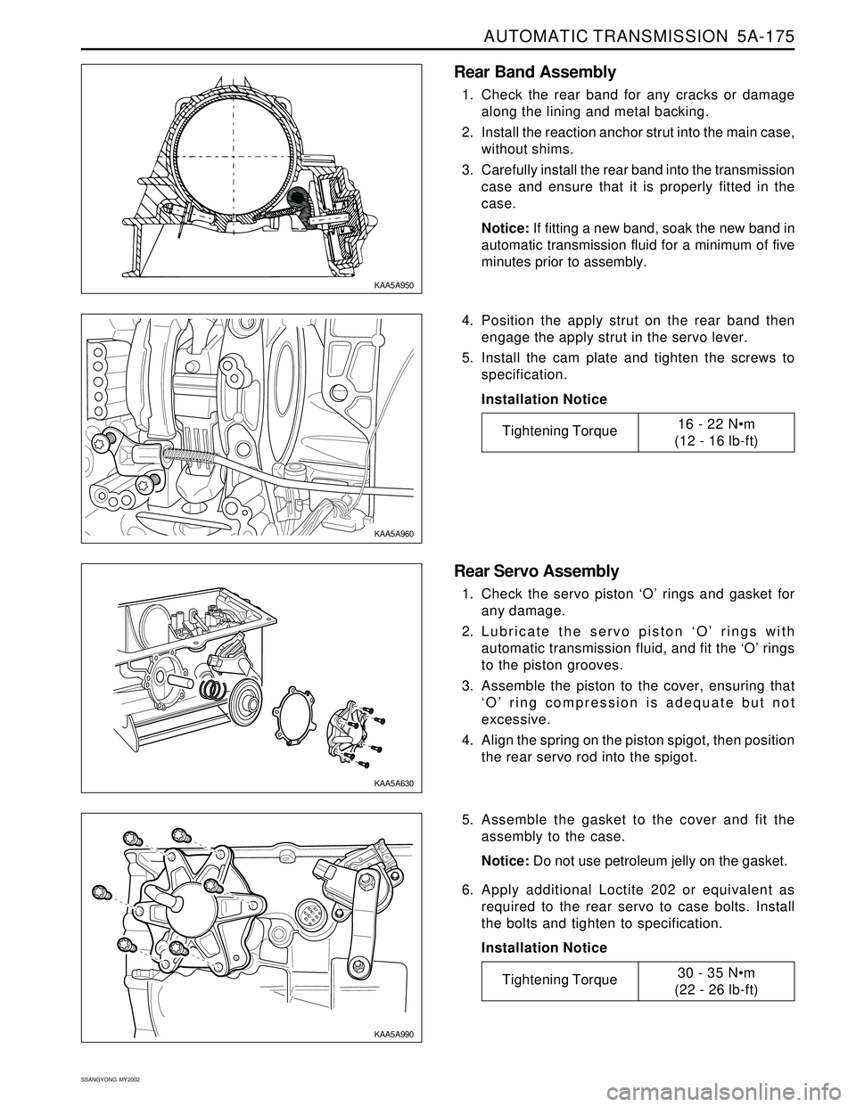
Rear Band Assembly
1. Check the rear band for any cracks or damage
along the lining and metal backing.
2. Install the reaction anchor strut into the main case,
without shims.
3. Carefully install the rear band into the transmission
case and ensure that it is properly fitted in the
case.
Notice: If fitting a new band, soak the new band in
automatic transmission fluid for a minimum of five
minutes prior to assembly.
4. Position the apply strut on the rear band then
engage the apply strut in the servo lever.
5. Install the cam plate and tighten the screws to
specification.
Installation Notice
Rear Servo Assembly
1. Check the servo piston ‘O’ rings and gasket for
any damage.
2. Lubricate the servo piston ‘O’ rings with
automatic transmission fluid, and fit the ‘O’ rings
to the piston grooves.
3. Assemble the piston to the cover, ensuring that
‘O’ ring compression is adequate but not
excessive.
4. Align the spring on the piston spigot, then position
the rear servo rod into the spigot.
5. Assemble the gasket to the cover and fit the
assembly to the case.
Notice: Do not use petroleum jelly on the gasket.
6. Apply additional Loctite 202 or equivalent as
required to the rear servo to case bolts. Install
the bolts and tighten to specification.
Installation Notice
KAA5A950
KAA5A960
KAA5A630
KAA5A990
Tightening Torque30 - 35 Nm
(22 - 26 lb-ft)
Tightening Torque16 - 22 Nm
(12 - 16 lb-ft)
Page 1271 of 2053
5A-176 AUTOMATIC TRANSMISSION
SSANGYONG MY2002
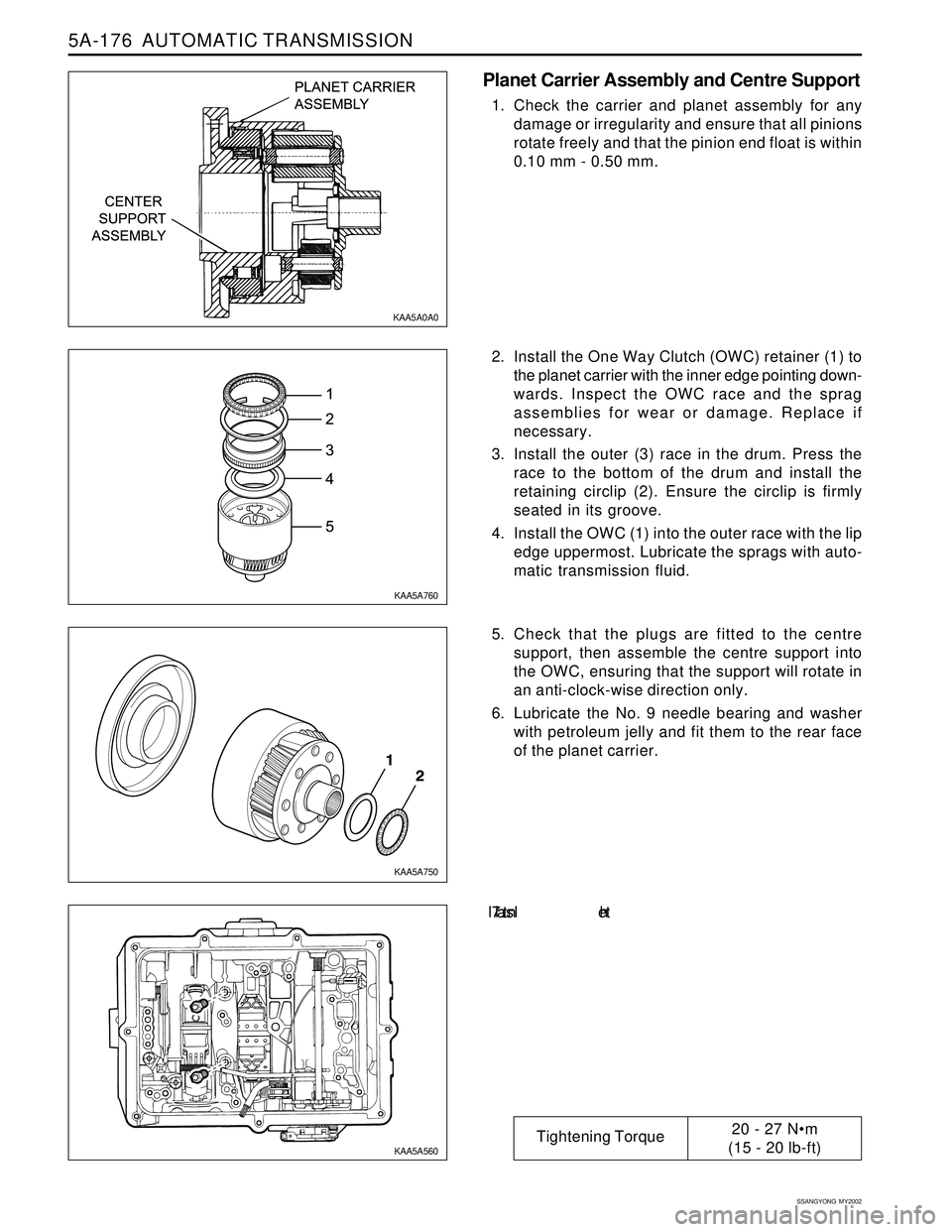
Planet Carrier Assembly and Centre Support
1. Check the carrier and planet assembly for any
damage or irregularity and ensure that all pinions
rotate freely and that the pinion end float is within
0.10 mm - 0.50 mm.
2. Install the One Way Clutch (OWC) retainer (1) to
the planet carrier with the inner edge pointing down-
wards. Inspect the OWC race and the sprag
assemblies for wear or damage. Replace if
necessary.
3. Install the outer (3) race in the drum. Press the
race to the bottom of the drum and install the
retaining circlip (2). Ensure the circlip is firmly
seated in its groove.
4. Install the OWC (1) into the outer race with the lip
edge uppermost. Lubricate the sprags with auto-
matic transmission fluid.
5. Check that the plugs are fitted to the centre
support, then assemble the centre support into
the OWC, ensuring that the support will rotate in
an anti-clock-wise direction only.
6. Lubricate the No. 9 needle bearing and washer
with petroleum jelly and fit them to the rear face
of the planet carrier.
7. In s t a l l th e
KAA5A0A0
KAA5A760
KAA5A750
KAA5A560
Tightening Torque20 - 27 Nm
(15 - 20 lb-ft)