1997 SSANGYONG KORANDO check transmission fluid
[x] Cancel search: check transmission fluidPage 1134 of 2053
5A-40 AUTOMATIC TRANSMISSION
SSANGYONG MY2002
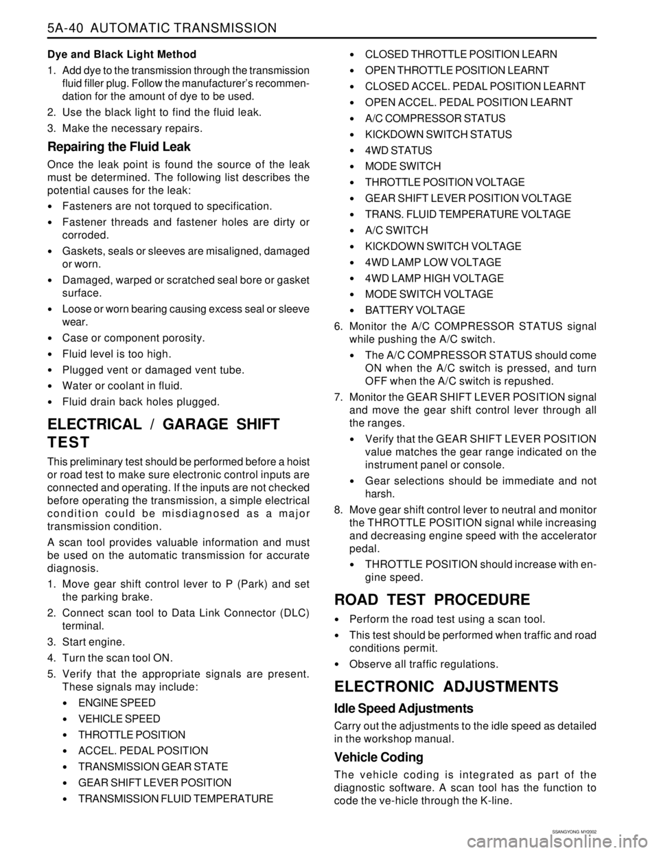
Dye and Black Light Method
1. Add dye to the transmission through the transmission
fluid filler plug. Follow the manufacturer’s recommen-
dation for the amount of dye to be used.
2. Use the black light to find the fluid leak.
3. Make the necessary repairs.
Repairing the Fluid Leak
Once the leak point is found the source of the leak
must be determined. The following list describes the
potential causes for the leak:
Fasteners are not torqued to specification.
Fastener threads and fastener holes are dirty or
corroded.
Gaskets, seals or sleeves are misaligned, damaged
or worn.
Damaged, warped or scratched seal bore or gasket
surface.
Loose or worn bearing causing excess seal or sleeve
wear.
Case or component porosity.
Fluid level is too high.
Plugged vent or damaged vent tube.
Water or coolant in fluid.
Fluid drain back holes plugged.
ELECTRICAL / GARAGE SHIFT
TEST
This preliminary test should be performed before a hoist
or road test to make sure electronic control inputs are
connected and operating. If the inputs are not checked
before operating the transmission, a simple electrical
condition could be misdiagnosed as a major
transmission condition.
A scan tool provides valuable information and must
be used on the automatic transmission for accurate
diagnosis.
1. Move gear shift control lever to P (Park) and set
the parking brake.
2. Connect scan tool to Data Link Connector (DLC)
terminal.
3. Start engine.
4. Turn the scan tool ON.
5. Verify that the appropriate signals are present.
These signals may include:
ENGINE SPEED
VEHICLE SPEED
THROTTLE POSITION
ACCEL. PEDAL POSITION
TRANSMISSION GEAR STATE
GEAR SHIFT LEVER POSITION
TRANSMISSION FLUID TEMPERATURE
CLOSED THROTTLE POSITION LEARN
OPEN THROTTLE POSITION LEARNT
CLOSED ACCEL. PEDAL POSITION LEARNT
OPEN ACCEL. PEDAL POSITION LEARNT
A/C COMPRESSOR STATUS
KICKDOWN SWITCH STATUS
4WD STATUS
MODE SWITCH
THROTTLE POSITION VOLTAGE
GEAR SHIFT LEVER POSITION VOLTAGE
TRANS. FLUID TEMPERATURE VOLTAGE
A/C SWITCH
KICKDOWN SWITCH VOLTAGE
4WD LAMP LOW VOLTAGE
4WD LAMP HIGH VOLTAGE
MODE SWITCH VOLTAGE
BATTERY VOLTAGE
6. Monitor the A/C COMPRESSOR STATUS signal
while pushing the A/C switch.
The A/C COMPRESSOR STATUS should come
ON when the A/C switch is pressed, and turn
OFF when the A/C switch is repushed.
7. Monitor the GEAR SHIFT LEVER POSITION signal
and move the gear shift control lever through all
the ranges.
Verify that the GEAR SHIFT LEVER POSITION
value matches the gear range indicated on the
instrument panel or console.
Gear selections should be immediate and not
harsh.
8. Move gear shift control lever to neutral and monitor
the THROTTLE POSITION signal while increasing
and decreasing engine speed with the accelerator
pedal.
THROTTLE POSITION should increase with en-
gine speed.
ROAD TEST PROCEDURE
Perform the road test using a scan tool.
This test should be performed when traffic and road
conditions permit.
Observe all traffic regulations.
ELECTRONIC ADJUSTMENTS
Idle Speed Adjustments
Carry out the adjustments to the idle speed as detailed
in the workshop manual.
Vehicle Coding
The vehicle coding is integrated as part of the
diagnostic software. A scan tool has the function to
code the ve-hicle through the K-line.
Page 1135 of 2053
5A-40 AUTOMATIC TRANSMISSION
SSANGYONG MY2002
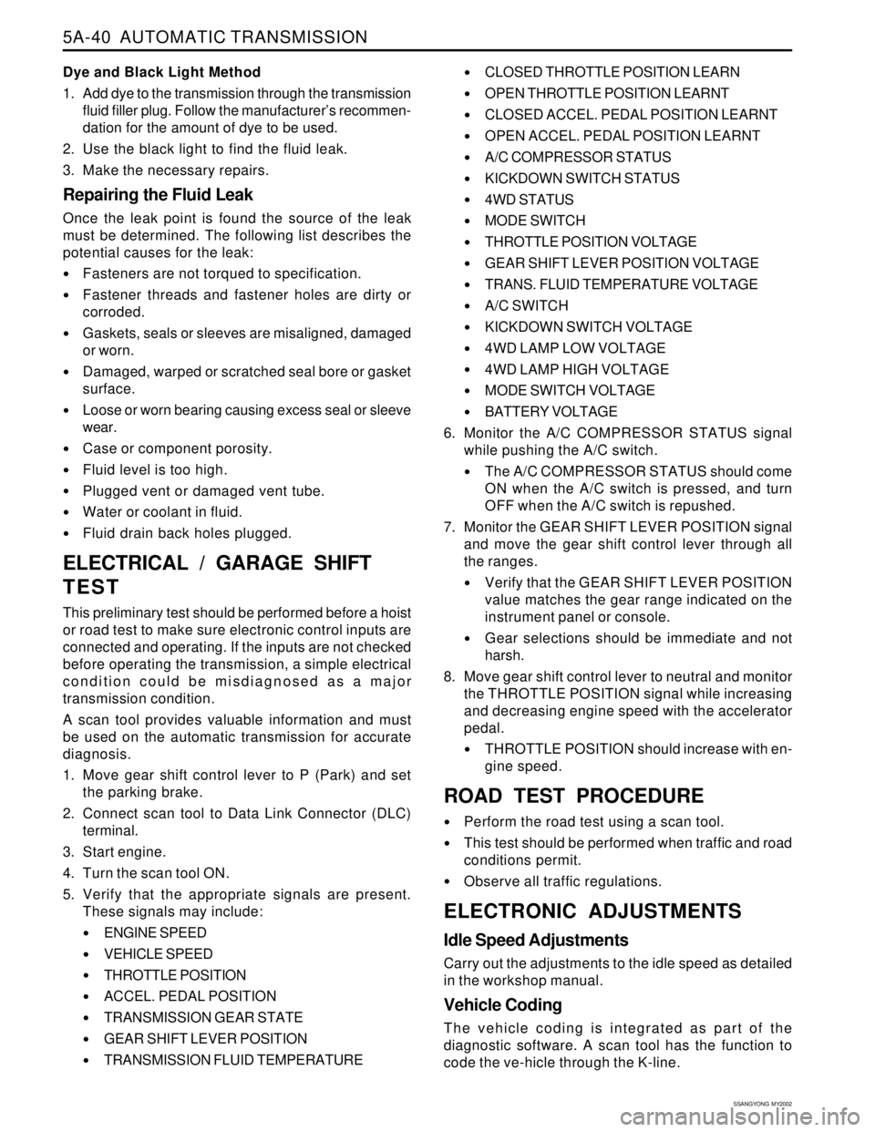
Dye and Black Light Method
1. Add dye to the transmission through the transmission
fluid filler plug. Follow the manufacturer’s recommen-
dation for the amount of dye to be used.
2. Use the black light to find the fluid leak.
3. Make the necessary repairs.
Repairing the Fluid Leak
Once the leak point is found the source of the leak
must be determined. The following list describes the
potential causes for the leak:
Fasteners are not torqued to specification.
Fastener threads and fastener holes are dirty or
corroded.
Gaskets, seals or sleeves are misaligned, damaged
or worn.
Damaged, warped or scratched seal bore or gasket
surface.
Loose or worn bearing causing excess seal or sleeve
wear.
Case or component porosity.
Fluid level is too high.
Plugged vent or damaged vent tube.
Water or coolant in fluid.
Fluid drain back holes plugged.
ELECTRICAL / GARAGE SHIFT
TEST
This preliminary test should be performed before a hoist
or road test to make sure electronic control inputs are
connected and operating. If the inputs are not checked
before operating the transmission, a simple electrical
condition could be misdiagnosed as a major
transmission condition.
A scan tool provides valuable information and must
be used on the automatic transmission for accurate
diagnosis.
1. Move gear shift control lever to P (Park) and set
the parking brake.
2. Connect scan tool to Data Link Connector (DLC)
terminal.
3. Start engine.
4. Turn the scan tool ON.
5. Verify that the appropriate signals are present.
These signals may include:
ENGINE SPEED
VEHICLE SPEED
THROTTLE POSITION
ACCEL. PEDAL POSITION
TRANSMISSION GEAR STATE
GEAR SHIFT LEVER POSITION
TRANSMISSION FLUID TEMPERATURE
CLOSED THROTTLE POSITION LEARN
OPEN THROTTLE POSITION LEARNT
CLOSED ACCEL. PEDAL POSITION LEARNT
OPEN ACCEL. PEDAL POSITION LEARNT
A/C COMPRESSOR STATUS
KICKDOWN SWITCH STATUS
4WD STATUS
MODE SWITCH
THROTTLE POSITION VOLTAGE
GEAR SHIFT LEVER POSITION VOLTAGE
TRANS. FLUID TEMPERATURE VOLTAGE
A/C SWITCH
KICKDOWN SWITCH VOLTAGE
4WD LAMP LOW VOLTAGE
4WD LAMP HIGH VOLTAGE
MODE SWITCH VOLTAGE
BATTERY VOLTAGE
6. Monitor the A/C COMPRESSOR STATUS signal
while pushing the A/C switch.
The A/C COMPRESSOR STATUS should come
ON when the A/C switch is pressed, and turn
OFF when the A/C switch is repushed.
7. Monitor the GEAR SHIFT LEVER POSITION signal
and move the gear shift control lever through all
the ranges.
Verify that the GEAR SHIFT LEVER POSITION
value matches the gear range indicated on the
instrument panel or console.
Gear selections should be immediate and not
harsh.
8. Move gear shift control lever to neutral and monitor
the THROTTLE POSITION signal while increasing
and decreasing engine speed with the accelerator
pedal.
THROTTLE POSITION should increase with en-
gine speed.
ROAD TEST PROCEDURE
Perform the road test using a scan tool.
This test should be performed when traffic and road
conditions permit.
Observe all traffic regulations.
ELECTRONIC ADJUSTMENTS
Idle Speed Adjustments
Carry out the adjustments to the idle speed as detailed
in the workshop manual.
Vehicle Coding
The vehicle coding is integrated as part of the
diagnostic software. A scan tool has the function to
code the ve-hicle through the K-line.
Page 1136 of 2053
AUTOMATIC TRANSMISSION 5A-41
SSANGYONG MY2002
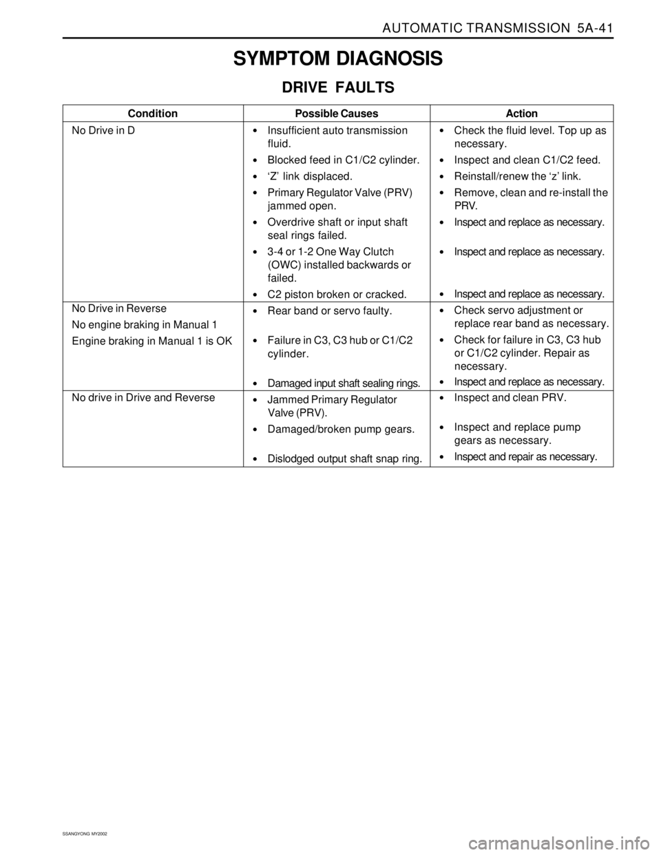
SYMPTOM DIAGNOSIS
DRIVE FAULTS
Condition
No Drive in DPossible Causes
Insufficient auto transmission
fluid.
Blocked feed in C1/C2 cylinder.
‘Z’ link displaced.
Primary Regulator Valve (PRV)
jammed open.
Overdrive shaft or input shaft
seal rings failed.
3-4 or 1-2 One Way Clutch
(OWC) installed backwards or
failed.
C2 piston broken or cracked.
Rear band or servo faulty.
Failure in C3, C3 hub or C1/C2
cylinder.
Damaged input shaft sealing rings.
Jammed Primary Regulator
Valve (PRV).
Damaged/broken pump gears.
Dislodged output shaft snap ring.Action
Check the fluid level. Top up as
necessary.
Inspect and clean C1/C2 feed.
Reinstall/renew the ‘z’ link.
Remove, clean and re-install the
PRV.
Inspect and replace as necessary.
Inspect and replace as necessary.
Inspect and replace as necessary.
Check servo adjustment or
replace rear band as necessary.
Check for failure in C3, C3 hub
or C1/C2 cylinder. Repair as
necessary.
Inspect and replace as necessary.
Inspect and clean PRV.
Inspect and replace pump
gears as necessary.
Inspect and repair as necessary.
No Drive in Reverse
No engine braking in Manual 1
Engine braking in Manual 1 is OK
No drive in Drive and Reverse
Page 1139 of 2053
5A-44 AUTOMATIC TRANSMISSION
SSANGYONG MY2002
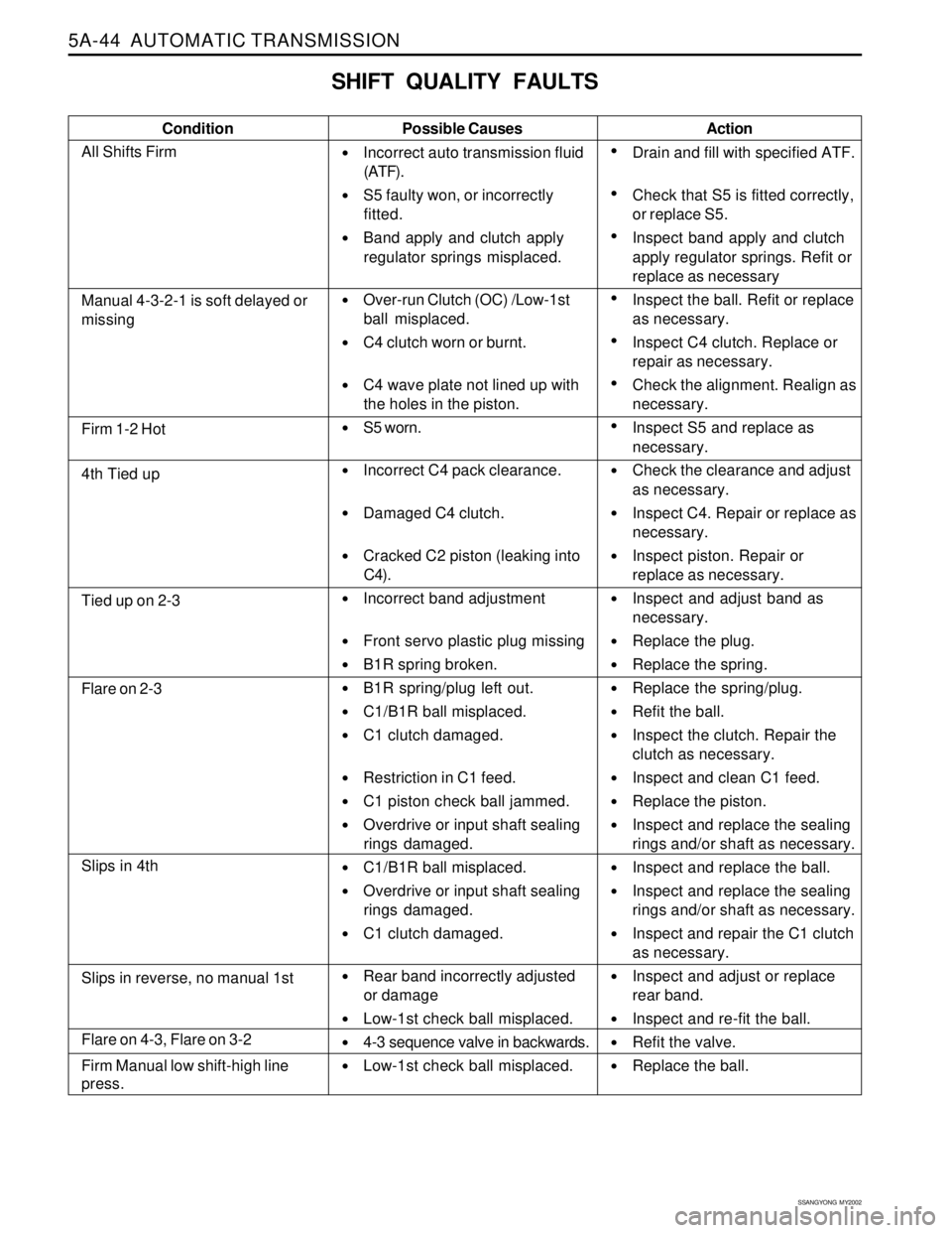
SHIFT QUALITY FAULTS
Condition Possible Causes
Incorrect auto transmission fluid
(ATF).
S5 faulty won, or incorrectly
fitted.
Band apply and clutch apply
regulator springs misplaced.
Over-run Clutch (OC) /Low-1st
ball misplaced.
C4 clutch worn or burnt.
C4 wave plate not lined up with
the holes in the piston.
S5 worn.
Incorrect C4 pack clearance.
Damaged C4 clutch.
Cracked C2 piston (leaking into
C4).
Incorrect band adjustment
Front servo plastic plug missing
B1R spring broken.
B1R spring/plug left out.
C1/B1R ball misplaced.
C1 clutch damaged.
Restriction in C1 feed.
C1 piston check ball jammed.
Overdrive or input shaft sealing
rings damaged.
C1/B1R ball misplaced.
Overdrive or input shaft sealing
rings damaged.
C1 clutch damaged.
Rear band incorrectly adjusted
or damage
Low-1st check ball misplaced.
4-3 sequence valve in backwards.
Low-1st check ball misplaced.Action
Drain and fill with specified ATF.
Check that S5 is fitted correctly,
or replace S5.
Inspect band apply and clutch
apply regulator springs. Refit or
replace as necessary
Inspect the ball. Refit or replace
as necessary.
Inspect C4 clutch. Replace or
repair as necessary.
Check the alignment. Realign as
necessary.
Inspect S5 and replace as
necessary.
Check the clearance and adjust
as necessary.
Inspect C4. Repair or replace as
necessary.
Inspect piston. Repair or
replace as necessary.
Inspect and adjust band as
necessary.
Replace the plug.
Replace the spring.
Replace the spring/plug.
Refit the ball.
Inspect the clutch. Repair the
clutch as necessary.
Inspect and clean C1 feed.
Replace the piston.
Inspect and replace the sealing
rings and/or shaft as necessary.
Inspect and replace the ball.
Inspect and replace the sealing
rings and/or shaft as necessary.
Inspect and repair the C1 clutch
as necessary.
Inspect and adjust or replace
rear band.
Inspect and re-fit the ball.
Refit the valve.
Replace the ball.
Manual 4-3-2-1 is soft delayed or
missing
Firm 1-2 Hot
4th Tied up
Tied up on 2-3
Flare on 2-3
Slips in 4th
Flare on 4-3, Flare on 3-2
Firm Manual low shift-high line
press.
Slips in reverse, no manual 1st
All Shifts Firm
Page 1143 of 2053
5A-48 AUTOMATIC TRANSMISSION
SSANGYONG MY2002
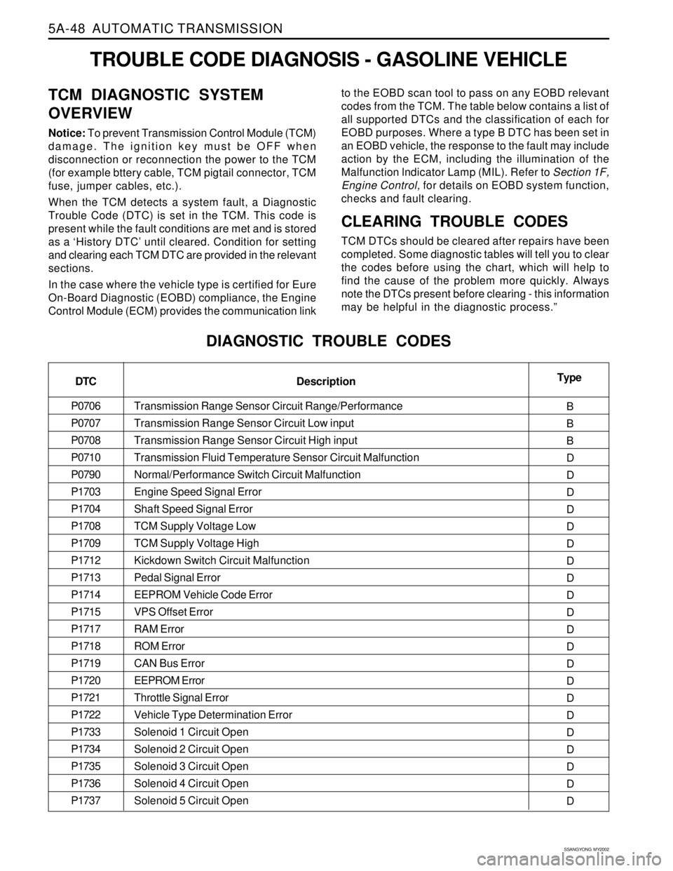
TROUBLE CODE DIAGNOSIS - GASOLINE VEHICLE
TCM DIAGNOSTIC SYSTEM
OVERVIEW
Notice: To prevent Transmission Control Module (TCM)
damage. The ignition key must be OFF when
disconnection or reconnection the power to the TCM
(for example bttery cable, TCM pigtail connector, TCM
fuse, jumper cables, etc.).
When the TCM detects a system fault, a Diagnostic
Trouble Code (DTC) is set in the TCM. This code is
present while the fault conditions are met and is stored
as a ‘History DTC’ until cleared. Condition for setting
and clearing each TCM DTC are provided in the relevant
sections.
In the case where the vehicle type is certified for Eure
On-Board Diagnostic (EOBD) compliance, the Engine
Control Module (ECM) provides the communication linkto the EOBD scan tool to pass on any EOBD relevant
codes from the TCM. The table below contains a list of
all supported DTCs and the classification of each for
EOBD purposes. Where a type B DTC has been set in
an EOBD vehicle, the response to the fault may include
action by the ECM, including the illumination of the
Malfunction lndicator Lamp (MIL). Refer to Section 1F,
Engine Control, for details on EOBD system function,
checks and fault clearing.
CLEARING TROUBLE CODES
TCM DTCs should be cleared after repairs have been
completed. Some diagnostic tables will tell you to clear
the codes before using the chart, which will help to
find the cause of the problem more quickly. Always
note the DTCs present before clearing - this information
may be helpful in the diagnostic process.”
DIAGNOSTIC TROUBLE CODES
DTC
P0706
P0707
P0708
P0710
P0790
P1703
P1704
P1708
P1709
P1712
P1713
P1714
P1715
P1717
P1718
P1719
P1720
P1721
P1722
P1733
P1734
P1735
P1736
P1737Type
B
B
B
D
D
D
D
D
D
D
D
D
D
D
D
D
D
D
D
D
D
D
D
D Description
Transmission Range Sensor Circuit Range/Performance
Transmission Range Sensor Circuit Low input
Transmission Range Sensor Circuit High input
Transmission Fluid Temperature Sensor Circuit Malfunction
Normal/Performance Switch Circuit Malfunction
Engine Speed Signal Error
Shaft Speed Signal Error
TCM Supply Voltage Low
TCM Supply Voltage High
Kickdown Switch Circuit Malfunction
Pedal Signal Error
EEPROM Vehicle Code Error
VPS Offset Error
RAM Error
ROM Error
CAN Bus Error
EEPROM Error
Throttle Signal Error
Vehicle Type Determination Error
Solenoid 1 Circuit Open
Solenoid 2 Circuit Open
Solenoid 3 Circuit Open
Solenoid 4 Circuit Open
Solenoid 5 Circuit Open
Page 1157 of 2053
5A-62 AUTOMATIC TRANSMISSION
SSANGYONG MY2002
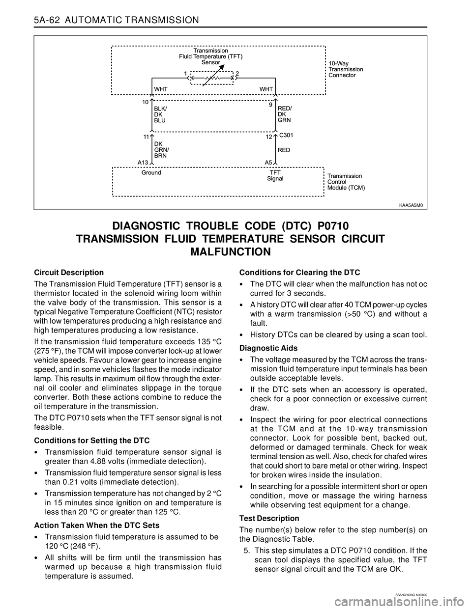
Circuit Description
The Transmission Fluid Temperature (TFT) sensor is a
thermistor located in the solenoid wiring loom within
the valve body of the transmission. This sensor is a
typical Negative Temperature Coefficient (NTC) resistor
with low temperatures producing a high resistance and
high temperatures producing a low resistance.
If the transmission fluid temperature exceeds 135 °C
(275 °F), the TCM will impose converter lock-up at lower
vehicle speeds. Favour a lower gear to increase engine
speed, and in some vehicles flashes the mode indicator
lamp. This results in maximum oil flow through the exter-
nal oil cooler and eliminates slippage in the torque
converter. Both these actions combine to reduce the
oil temperature in the transmission.
The DTC P0710 sets when the TFT sensor signal is not
feasible.
Conditions for Setting the DTC
Transmission fluid temperature sensor signal is
greater than 4.88 volts (immediate detection).
Transmission fluid temperature sensor signal is less
than 0.21 volts (immediate detection).
Transmission temperature has not changed by 2 °C
in 15 minutes since ignition on and temperature is
less than 20 °C or greater than 125 °C.
Action Taken When the DTC Sets
Transmission fluid temperature is assumed to be
120 °C (248 °F).
All shifts will be firm until the transmission has
warmed up because a high transmission fluid
temperature is assumed.
DIAGNOSTIC TROUBLE CODE (DTC) P0710
TRANSMISSION FLUID TEMPERATURE SENSOR CIRCUIT
MALFUNCTION
Conditions for Clearing the DTC
The DTC will clear when the malfunction has not oc
curred for 3 seconds.
A history DTC will clear after 40 TCM power-up cycles
with a warm transmission (>50 °C) and without a
fault.
History DTCs can be cleared by using a scan tool.
Diagnostic Aids
The voltage measured by the TCM across the trans-
mission fluid temperature input terminals has been
outside acceptable levels.
If the DTC sets when an accessory is operated,
check for a poor connection or excessive current
draw.
Inspect the wiring for poor electrical connections
at the TCM and at the 10-way transmission
connector. Look for possible bent, backed out,
deformed or damaged terminals. Check for weak
terminal tension as well. Also, check for chafed wires
that could short to bare metal or other wiring. Inspect
for broken wires inside the insulation.
In searching for a possible intermittent short or open
condition, move or massage the wiring harness
while observing test equipment for a change.
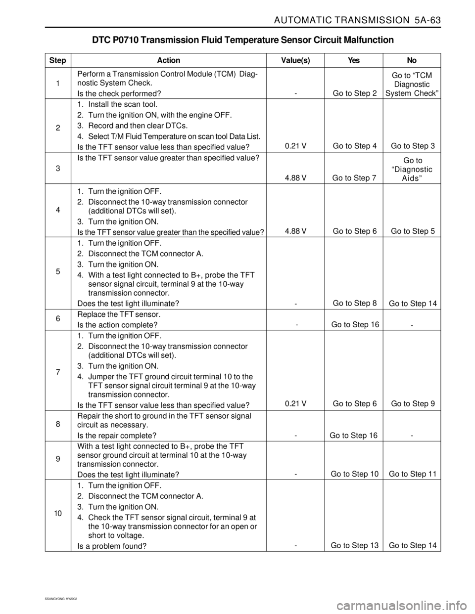
Test Description
The number(s) below refer to the step number(s) on
the Diagnostic Table.
5. This step simulates a DTC P0710 condition. If the
scan tool displays the specified value, the TFT
sensor signal circuit and the TCM are OK.
KAA5A5M0
Page 1158 of 2053
AUTOMATIC TRANSMISSION 5A-63
SSANGYONG MY2002
DTC P0710 Transmission Fluid Temperature Sensor Circuit Malfunction
1Perform a Transmission Control Module (TCM) Diag-
nostic System Check.
Is the check performed?
1. Install the scan tool.
2. Turn the ignition ON, with the engine OFF.
3. Record and then clear DTCs.
4. Select T/M Fluid Temperature on scan tool Data List.
Is the TFT sensor value less than specified value?
Is the TFT sensor value greater than specified value?
1. Turn the ignition OFF.
2. Disconnect the 10-way transmission connector
(additional DTCs will set).
3. Turn the ignition ON.
Is the TFT sensor value greater than the specified value?
1. Turn the ignition OFF.
2. Disconnect the TCM connector A.
3. Turn the ignition ON.
4. With a test light connected to B+, probe the TFT
sensor signal circuit, terminal 9 at the 10-way
transmission connector.
Does the test light illuminate?
Replace the TFT sensor.
Is the action complete?
1. Turn the ignition OFF.
2. Disconnect the 10-way transmission connector
(additional DTCs will set).
3. Turn the ignition ON.
4. Jumper the TFT ground circuit terminal 10 to the
TFT sensor signal circuit terminal 9 at the 10-way
transmission connector.
Is the TFT sensor value less than specified value?
Repair the short to ground in the TFT sensor signal
circuit as necessary.
Is the repair complete?
With a test light connected to B+, probe the TFT
sensor ground circuit at terminal 10 at the 10-way
transmission connector.
Does the test light illuminate?
1. Turn the ignition OFF.
2. Disconnect the TCM connector A.
3. Turn the ignition ON.
4. Check the TFT sensor signal circuit, terminal 9 at
the 10-way transmission connector for an open or
short to voltage.
Is a problem found?
StepAction Value(s) Yes No
2
3
- Go to Step 8
Go to Step 14 5
- Go to Step 16
- 6 4
7
0.21 V Go to Step 6 Go to Step 9
8
9
- Go to Step 2Go to “TCM
Diagnostic
System Check”
0.21 V Go to Step 4 Go to Step 3
4.88 V Go to Step 7 Go to
“Diagnostic
Aids”
10
- Go to Step 13 Go to Step 14
- Go to Step 10 Go to Step 11
- Go to Step 16 -
4.88 V Go to Step 6 Go to Step 5
Page 1159 of 2053
5A-64 AUTOMATIC TRANSMISSION
SSANGYONG MY2002
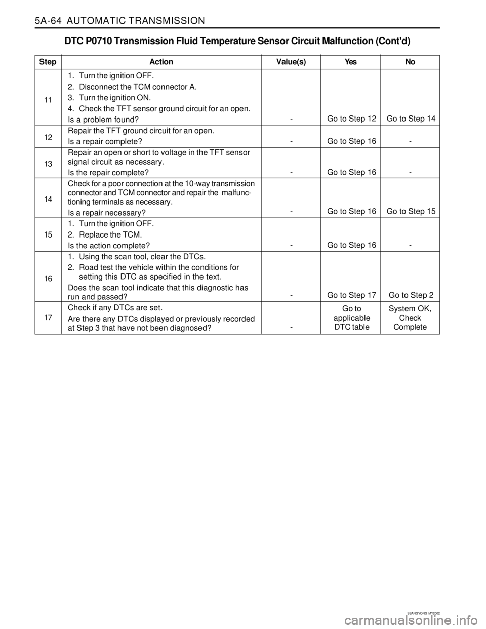
DTC P0710 Transmission Fluid Temperature Sensor Circuit Malfunction (Cont'd)
1. Turn the ignition OFF.
2. Disconnect the TCM connector A.
3. Turn the ignition ON.
4. Check the TFT sensor ground circuit for an open.
Is a problem found?
Repair the TFT ground circuit for an open.
Is a repair complete?
Repair an open or short to voltage in the TFT sensor
signal circuit as necessary.
Is the repair complete?
Check for a poor connection at the 10-way transmission
connector and TCM connector and repair the malfunc-
tioning terminals as necessary.
Is a repair necessary?
1. Turn the ignition OFF.
2. Replace the TCM.
Is the action complete?
1. Using the scan tool, clear the DTCs.
2. Road test the vehicle within the conditions for
setting this DTC as specified in the text.
Does the scan tool indicate that this diagnostic has
run and passed?
Check if any DTCs are set.
Are there any DTCs displayed or previously recorded
at Step 3 that have not been diagnosed?
StepAction Value(s) Yes No
11
12
- Go to Step 12 Go to Step 14
14
- Go to Step 16 -
15 13
- Go to Step 16 -
16
- Go to Step 16 Go to Step 15
17
- Go to Step 16 -
- Go to Step 17 Go to Step 2
-Go to
applicable
DTC tableSystem OK,
Check
Complete