1997 SSANGYONG KORANDO section 2c
[x] Cancel search: section 2cPage 1675 of 2053
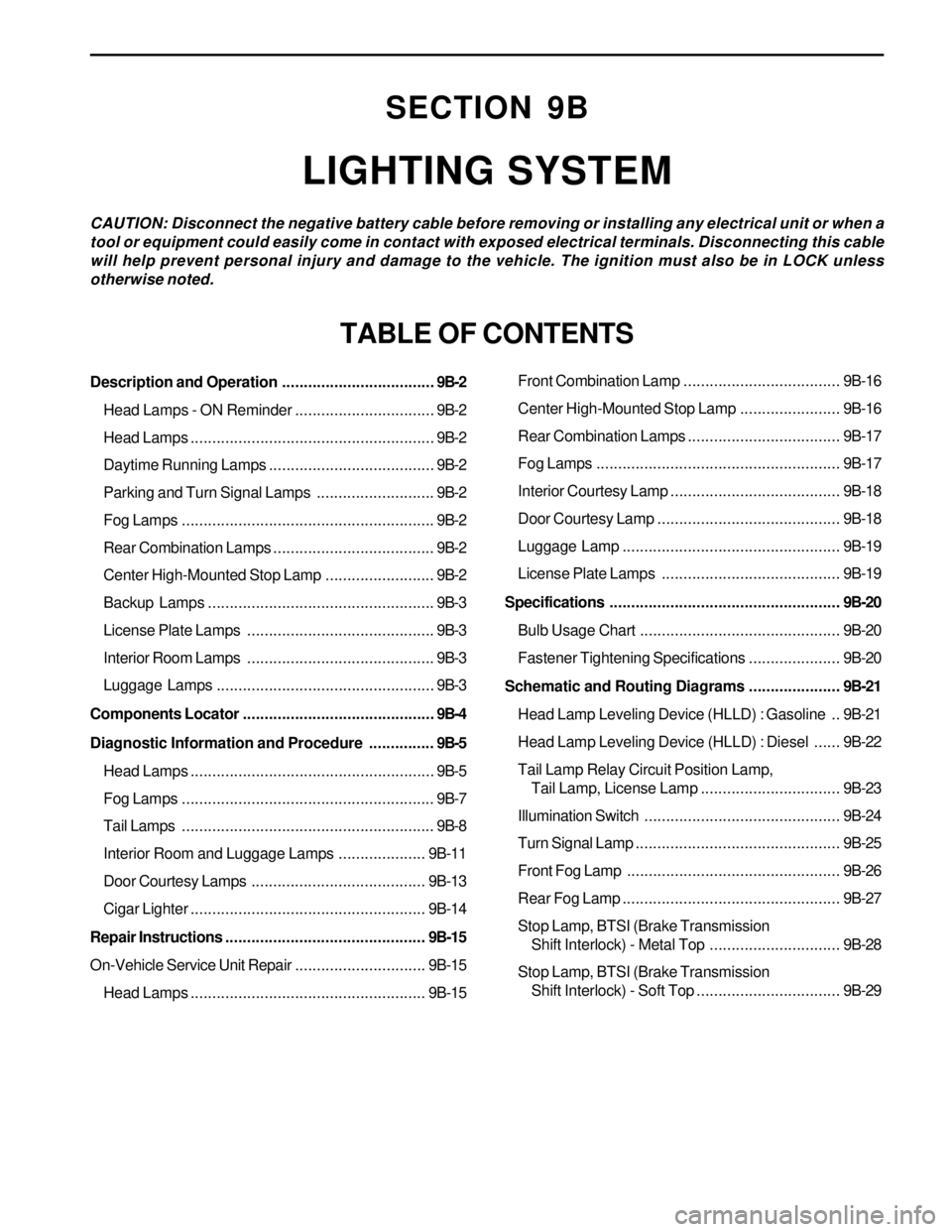
SECTION 9B
LIGHTING SYSTEM
CAUTION: Disconnect the negative battery cable before removing or installing any electrical unit or when a
tool or equipment could easily come in contact with exposed electrical terminals. Disconnecting this cable
will help prevent personal injury and damage to the vehicle. The ignition must also be in LOCK unless
otherwise noted.
TABLE OF CONTENTS
Description and Operation...................................9B-2
Head Lamps - ON Reminder................................9B-2
Head Lamps........................................................9B-2
Daytime Running Lamps......................................9B-2
Parking and Turn Signal Lamps...........................9B-2
Fog Lamps..........................................................9B-2
Rear Combination Lamps.....................................9B-2
Center High-Mounted Stop Lamp.........................9B-2
Backup Lamps....................................................9B-3
License Plate Lamps ...........................................9B-3
Interior Room Lamps ...........................................9B-3
Luggage Lamps..................................................9B-3
Components Locator............................................9B-4
Diagnostic Information and Procedure...............9B-5
Head Lamps........................................................9B-5
Fog Lamps..........................................................9B-7
Tail Lamps..........................................................9B-8
Interior Room and Luggage Lamps....................9B-11
Door Courtesy Lamps ........................................9B-13
Cigar Lighter......................................................9B-14
Repair Instructions..............................................9B-15
On-Vehicle Service Unit Repair..............................9B-15
Head Lamps......................................................9B-15Front Combination Lamp....................................9B-16
Center High-Mounted Stop Lamp.......................9B-16
Rear Combination Lamps...................................9B-17
Fog Lamps........................................................9B-17
Interior Courtesy Lamp .......................................9B-18
Door Courtesy Lamp ..........................................9B-18
Luggage Lamp..................................................9B-19
License Plate Lamps .........................................9B-19
Specifications.....................................................9B-20
Bulb Usage Chart..............................................9B-20
Fastener Tightening Specifications.....................9B-20
Schematic and Routing Diagrams.....................9B-21
Head Lamp Leveling Device (HLLD) : Gasoline ..9B-21
Head Lamp Leveling Device (HLLD) : Diesel......9B-22
Tail Lamp Relay Circuit Position Lamp,
Tail Lamp, License Lamp................................9B-23
Illumination Switch.............................................9B-24
Turn Signal Lamp...............................................9B-25
Front Fog Lamp.................................................9B-26
Rear Fog Lamp..................................................9B-27
Stop Lamp, BTSI (Brake Transmission
Shift Interlock) - Metal Top..............................9B-28
Stop Lamp, BTSI (Brake Transmission
Shift Interlock) - Soft Top.................................9B-29
Page 1676 of 2053
SSANGYONG MY2002
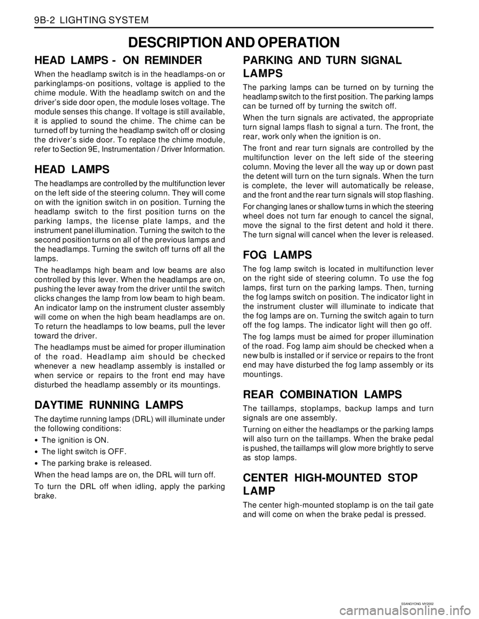
9B-2 LIGHTING SYSTEM
DESCRIPTION AND OPERATION
HEAD LAMPS - ON REMINDER
When the headlamp switch is in the headlamps-on or
parkinglamps-on positions, voltage is applied to the
chime module. With the headlamp switch on and the
driver’s side door open, the module loses voltage. The
module senses this change. If voltage is still available,
it is applied to sound the chime. The chime can be
turned off by turning the headlamp switch off or closing
the driver’s side door. To replace the chime module,
refer to Section 9E, Instrumentation / Driver Information.
HEAD LAMPS
The headlamps are controlled by the multifunction lever
on the left side of the steering column. They will come
on with the ignition switch in on position. Turning the
headlamp switch to the first position turns on the
parking lamps, the license plate lamps, and the
instrument panel illumination. Turning the switch to the
second position turns on all of the previous lamps and
the headlamps. Turning the switch off turns off all the
lamps.
The headlamps high beam and low beams are also
controlled by this lever. When the headlamps are on,
pushing the lever away from the driver until the switch
clicks changes the lamp from low beam to high beam.
An indicator lamp on the instrument cluster assembly
will come on when the high beam headlamps are on.
To return the headlamps to low beams, pull the lever
toward the driver.
The headlamps must be aimed for proper illumination
of the road. Headlamp aim should be checked
whenever a new headlamp assembly is installed or
when service or repairs to the front end may have
disturbed the headlamp assembly or its mountings.
DAYTIME RUNNING LAMPS
The daytime running lamps (DRL) will illuminate under
the following conditions:
The ignition is ON.
The light switch is OFF.
The parking brake is released.
When the head lamps are on, the DRL will turn off.
To turn the DRL off when idling, apply the parking
brake.
PARKING AND TURN SIGNAL
LAMPS
The parking lamps can be turned on by turning the
headlamp switch to the first position. The parking lamps
can be turned off by turning the switch off.
When the turn signals are activated, the appropriate
turn signal lamps flash to signal a turn. The front, the
rear, work only when the ignition is on.
The front and rear turn signals are controlled by the
multifunction lever on the left side of the steering
column. Moving the lever all the way up or down past
the detent will turn on the turn signals. When the turn
is complete, the lever will automatically be release,
and the front and the rear turn signals will stop flashing.
For changing lanes or shallow turns in which the steering
wheel does not turn far enough to cancel the signal,
move the signal to the first detent and hold it there.
The turn signal will cancel when the lever is released.
FOG LAMPS
The fog lamp switch is located in multifunction lever
on the right side of steering column. To use the fog
lamps, first turn on the parking lamps. Then, turning
the fog lamps switch on position. The indicator light in
the instrument cluster will illuminate to indicate that
the fog lamps are on. Turning the switch again to turn
off the fog lamps. The indicator light will then go off.
The fog lamps must be aimed for proper illumination
of the road. Fog lamp aim should be checked when a
new bulb is installed or if service or repairs to the front
end may have disturbed the fog lamp assembly or its
mountings.
REAR COMBINATION LAMPS
The taillamps, stoplamps, backup lamps and turn
signals are one assembly.
Turning on either the headlamps or the parking lamps
will also turn on the taillamps. When the brake pedal
is pushed, the taillamps will glow more brightly to serve
as stop lamps.
CENTER HIGH-MOUNTED STOP
LAMP
The center high-mounted stoplamp is on the tail gate
and will come on when the brake pedal is pressed.
Page 1704 of 2053
SECTION 9C
HORNS
CAUTION: Disconnect the negative battery cable before removing or installing any electrical unit or when a
tool or equipment could easily come in contact with exposed electrical terminals. Disconnecting this cable
will help prevent personal injury and damage to the vehicle. The ignition must also be in LOCK unless
otherwise noted.
TABLE OF CONTENTS
Description and Operation.................................. 9C-2
Horns ................................................................. 9C-2
Components Locator ........................................... 9C-3
Lighting System................................................. 9C-3Repair Instructions............................................... 9C-4
On-Vehice Service Unit Repair............................... 9C-4
Dual Horns......................................................... 9C-4
Schematic and Routing Diagram....................... 9C-5
Horn Wiring System............................................ 9C-5
Page 1709 of 2053
Description and Operation.................................. 9D-2
Windshield Wiper System................................... 9D-2
Windshield Washer System................................ 9D-2
Components Locator ........................................... 9D-3
Lighting System................................................. 9D-3
Repair Instructions............................................... 9D-4
On-Vehice Service Unit Repair............................... 9D-4
Windshield Wiper Arm........................................ 9D-4
Windshield Wiper Motor...................................... 9D-4
Windshield Wiper Blade..................................... 9D-5
Windshield Washer Reservoir............................. 9D-5
SECTION 9D
WIPER, WASHER SYSTEMS
CAUTION: Disconnect the negative battery cable before removing or installing any electrical unit or when a
tool or equipment could easily come in contact with exposed electrical terminals. Disconnecting this cable
will help prevent personal injury and damage to the vehicle. The ignition must also be in LOCK unless
otherwise noted.
TABLE OF CONTENTS
Windshield Washer Pump................................... 9D-6
Windshield Washer Nozzles................................ 9D-6
Windshield Washer Hoses.................................. 9D-6
Rear Wiper Arm.................................................. 9D-6
Rear Wiper Motor................................................ 9D-7
Rear Washer Reservoir....................................... 9D-7
Specifications...................................................... 9D-8
Fastener Tightening Specifications...................... 9D-8
Schematic and Routing Diagrams...................... 9D-9
Windshield Wipers System................................. 9D-9
Page 1712 of 2053
SSANGYONG MY2002
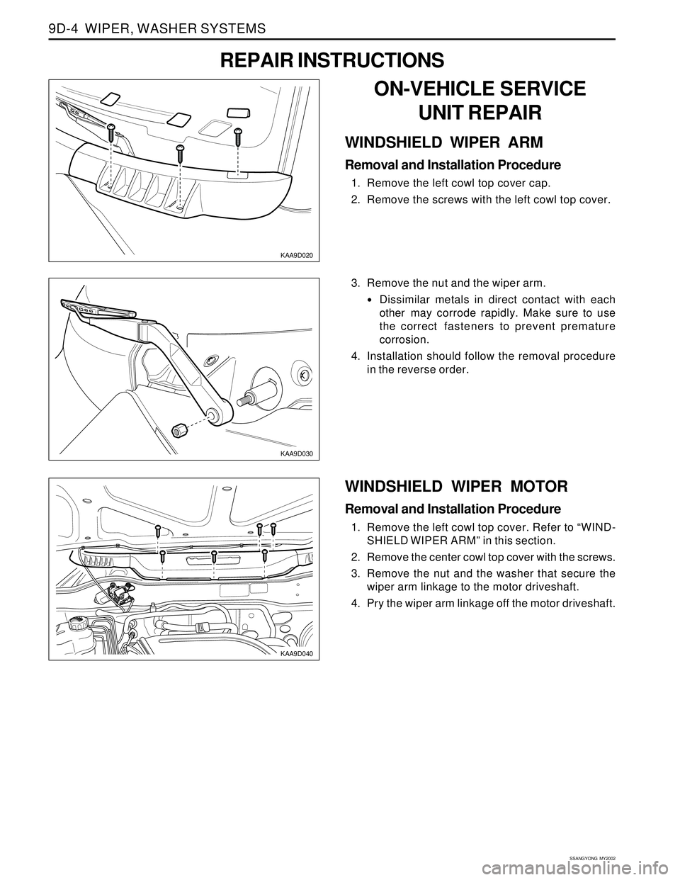
9D-4 WIPER, WASHER SYSTEMS
KAA9D030
KAA9D040
3. Remove the nut and the wiper arm.
•Dissimilar metals in direct contact with each
other may corrode rapidly. Make sure to use
the correct fasteners to prevent premature
corrosion.
4. Installation should follow the removal procedure
in the reverse order.
WINDSHIELD WIPER MOTOR
Removal and Installation Procedure
1. Remove the left cowl top cover. Refer to “WIND-
SHIELD WIPER ARM” in this section.
2. Remove the center cowl top cover with the screws.
3. Remove the nut and the washer that secure the
wiper arm linkage to the motor driveshaft.
4. Pry the wiper arm linkage off the motor driveshaft.
KAA9D020
ON-VEHICLE SERVICE
UNIT REPAIR
WINDSHIELD WIPER ARM
Removal and Installation Procedure
1. Remove the left cowl top cover cap.
2. Remove the screws with the left cowl top cover.
REPAIR INSTRUCTIONS
Page 1713 of 2053
WIPER, WASHER SYSTEMS 9D-5
SSANGYONG MY2002
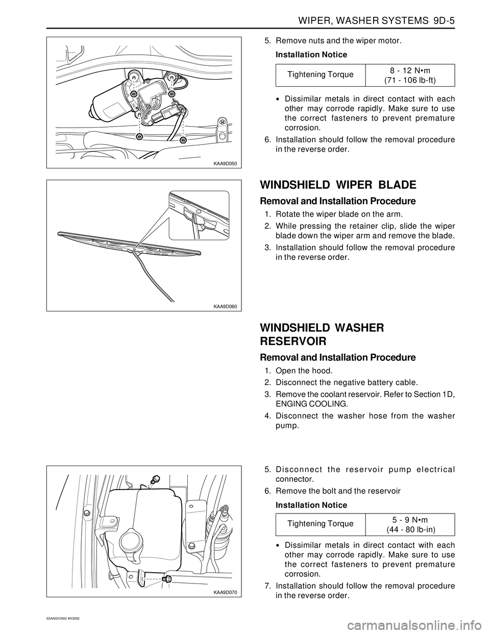
KAA9D050
KAA9D060
5. Remove nuts and the wiper motor.
Installation Notice
Dissimilar metals in direct contact with each
other may corrode rapidly. Make sure to use
the correct fasteners to prevent premature
corrosion.
6. Installation should follow the removal procedure
in the reverse order.
WINDSHIELD WASHER
RESERVOIR
Removal and Installation Procedure
1. Open the hood.
2. Disconnect the negative battery cable.
3. Remove the coolant reservoir. Refer to Section 1D,
ENGING COOLING.
4. Disconnect the washer hose from the washer
pump.
WINDSHIELD WIPER BLADE
Removal and Installation Procedure
1. Rotate the wiper blade on the arm.
2. While pressing the retainer clip, slide the wiper
blade down the wiper arm and remove the blade.
3. Installation should follow the removal procedure
in the reverse order.
Tightening Torque8 - 12 Nm
(71 - 106 lb-ft)
KAA9D070
5. Disconnect the reservoir pump electrical
connector.
6. Remove the bolt and the reservoir
Installation Notice
Dissimilar metals in direct contact with each
other may corrode rapidly. Make sure to use
the correct fasteners to prevent premature
corrosion.
7. Installation should follow the removal procedure
in the reverse order.
Tightening Torque5 - 9 Nm
(44 - 80 lb-in)
Page 1714 of 2053
SSANGYONG MY2002
9D-6 WIPER, WASHER SYSTEMS
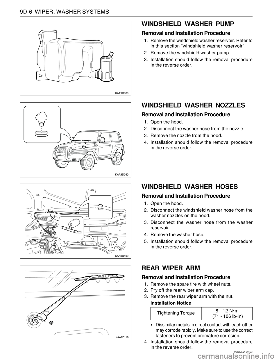
KAA9D080
KAA9D090
KAA9D100
WINDSHIELD WASHER PUMP
Removal and Installation Procedure
1. Remove the windshield washer reservoir. Refer to
in this section “windshield washer reservoir”.
2. Remove the windshield washer pump.
3. Installation should follow the removal procedure
in the reverse order.
WINDSHIELD WASHER HOSES
Removal and Installation Procedure
1. Open the hood.
2. Disconnect the windshield washer hose from the
washer nozzles on the hood.
3. Disconnect the washer hose from the washer
reservoir.
4. Remove the washer hose.
5. Installation should follow the removal procedure
in the reverse order.
KAA9D110
REAR WIPER ARM
Removal and Installation Procedure
1. Remove the spare tire with wheel nuts.
2. Pry off the rear wiper arm cap.
3. Remove the rear wiper arm with the nut.
Installation Notice
Dissimilar metals in direct contact with each other
may corrode rapidly. Make sure to use the correct
fasteners to prevent premature corrosion.
4. Installation should follow the removal procedure
in the reverse order.
WINDSHIELD WASHER NOZZLES
Removal and Installation Procedure
1. Open the hood.
2. Disconnect the washer hose from the nozzle.
3. Remove the nozzle from the hood.
4. Installation should follow the removal procedure
in the reverse order.
Tightening Torque8 - 12 Nm
(71 - 106 lb-in)
Page 1715 of 2053
WIPER, WASHER SYSTEMS 9D-7
SSANGYONG MY2002
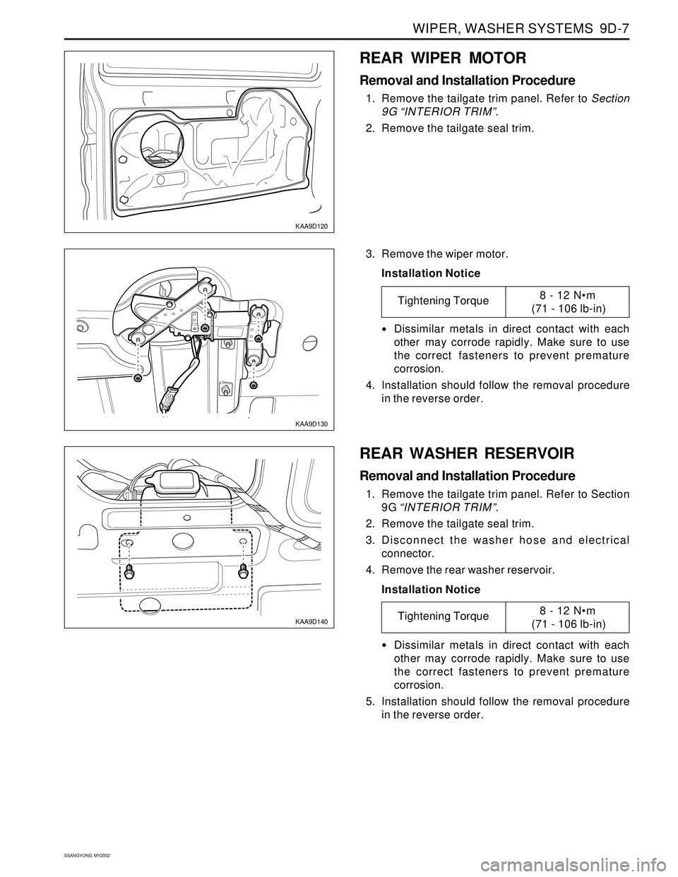
KAA9D120
KAA9D130
REAR WIPER MOTOR
Removal and Installation Procedure
1. Remove the tailgate trim panel. Refer to Section
9G “INTERIOR TRIM”.
2. Remove the tailgate seal trim.
3. Remove the wiper motor.
Installation Notice
Dissimilar metals in direct contact with each
other may corrode rapidly. Make sure to use
the correct fasteners to prevent premature
corrosion.
4. Installation should follow the removal procedure
in the reverse order.
Tightening Torque8 - 12 Nm
(71 - 106 lb-in)
KAA9D140
REAR WASHER RESERVOIR
Removal and Installation Procedure
1. Remove the tailgate trim panel. Refer to Section
9G “INTERIOR TRIM”.
2. Remove the tailgate seal trim.
3. Disconnect the washer hose and electrical
connector.
4. Remove the rear washer reservoir.
Installation Notice
Dissimilar metals in direct contact with each
other may corrode rapidly. Make sure to use
the correct fasteners to prevent premature
corrosion.
5. Installation should follow the removal procedure
in the reverse order.
Tightening Torque8 - 12 Nm
(71 - 106 lb-in)