Page 1759 of 2053

SECTION 9H
SEATS
TABLE OF CONTENTS
Components Locator............................................9H-2
Seats ...................................................................9H-2
Repair Instructions................................................9H-3
On-Vehicle Service Unit Repair................................9H-3
Front Seat............................................................9H-3
Front Seat Cushion..............................................9H-3
Front Seatback....................................................9H-4
Front Seat Guide Rail ...........................................9H-4
Front Seat Recliner Lever.....................................9H-5
Front Seat Trim....................................................9H-5
Head Restraint.....................................................9H-5Walk In Device....................................................9H-6
Front Seat Armrest...............................................9H-6
Rear Seat Armrest ...............................................9H-6
Rear Seat............................................................9H-7
50/50 Split Rear Seat Cushion Hinge....................9H-7
50/50 Split Rear Seat Cushion Lock Striker...........9H-8
Child Seat Anchorage ..........................................9H-8
Specifications.......................................................9H-9
Fastener Tightening Specifications.......................9H-9
Schematic and Routing Diagram......................9H-10
Seat Heater.......................................................9H-10
Page 1760 of 2053
SSANGYONG MY2002
9H-2 SEATS
COMPONENTS LOCATOR
SEATS
1 Seat A-FRT
2 Seat A-FRT
3 Head Rest Sleeve A
4 Head Rest A-FRT
5 Shield Cover
6 Bolt-Hex SEMS
7 G/Rail A-FRT
8 Recliner A-FRT
9 Lumber Support-Knob10 Seat-RR
11 Seat-RR
12 Arm Rest A-RR
13 Striker-RR Seat
14 Head Rest A-RR
15 Head Rest Sleeve A
16 Bolt-Hex SEMS
17 Bolt-Hex SEMS
KAA9H010
Page 1762 of 2053

SSANGYONG MY2002
9H-4 SEATS
KAA9H070
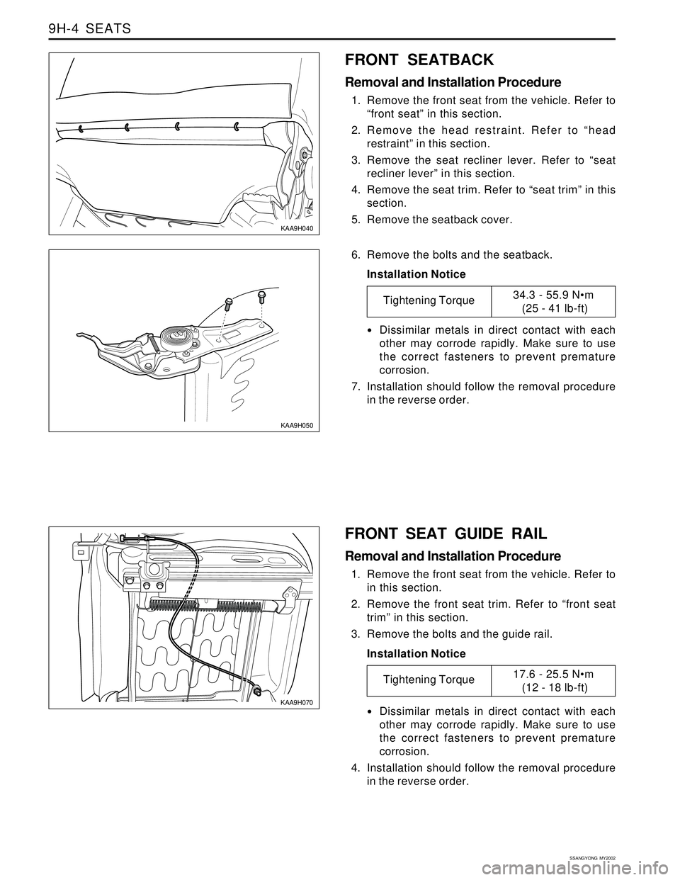
FRONT SEAT GUIDE RAIL
Removal and Installation Procedure
1. Remove the front seat from the vehicle. Refer to
in this section.
2. Remove the front seat trim. Refer to “front seat
trim” in this section.
3. Remove the bolts and the guide rail.
Installation Notice
KAA9H050
6. Remove the bolts and the seatback.
Installation Notice
Dissimilar metals in direct contact with each
other may corrode rapidly. Make sure to use
the correct fasteners to prevent premature
corrosion.
7. Installation should follow the removal procedure
in the reverse order.
Tightening Torque34.3 - 55.9 Nm
(25 - 41 lb-ft)
Dissimilar metals in direct contact with each
other may corrode rapidly. Make sure to use
the correct fasteners to prevent premature
corrosion.
4. Installation should follow the removal procedure
in the reverse order.
Tightening Torque17.6 - 25.5 Nm
(12 - 18 lb-ft)
KAA9H040
FRONT SEATBACK
Removal and Installation Procedure
1. Remove the front seat from the vehicle. Refer to
“front seat” in this section.
2. Remove the head restraint. Refer to “head
restraint” in this section.
3. Remove the seat recliner lever. Refer to “seat
recliner lever” in this section.
4. Remove the seat trim. Refer to “seat trim” in this
section.
5. Remove the seatback cover.
Page 1763 of 2053
SEATS 9H-5
SSANGYONG MY2002
KAA9H100
KAA9H080
KAA9H090
FRONT SEAT TRIM
Removal and Installation Procedure
1. Remove the recliner lever by rubber hammer. Refer
to “seat recliner lever” in this section.
2. Remove the screws and the seat trim.
3. Installation should follow the removal procedure
in the reverse order.
FRONT SEAT RECLINER LEVER
Removal and Installation Procedure
1. Remove the seat recliner lever by rubber hammer.
2. Installation should follow the removal procedure
in the reverse order.
HEAD RESTRAINT
Removal and Installation Procedure
1. Press in the head restraint adjust button and
remove the head restraint from the seatback.
KAA9H110
2. Insert two flat head screwdrivers down the front
and back side of the guide sleeves.
3. With the screwdrivers, press in the retaining
latches and remove the guide sleeves.
4. Installation should follow the removal procedure
in the reverse order.
Page 1823 of 2053

SSANGYONG MY2002
9P-6 DOORS
KAA9P050
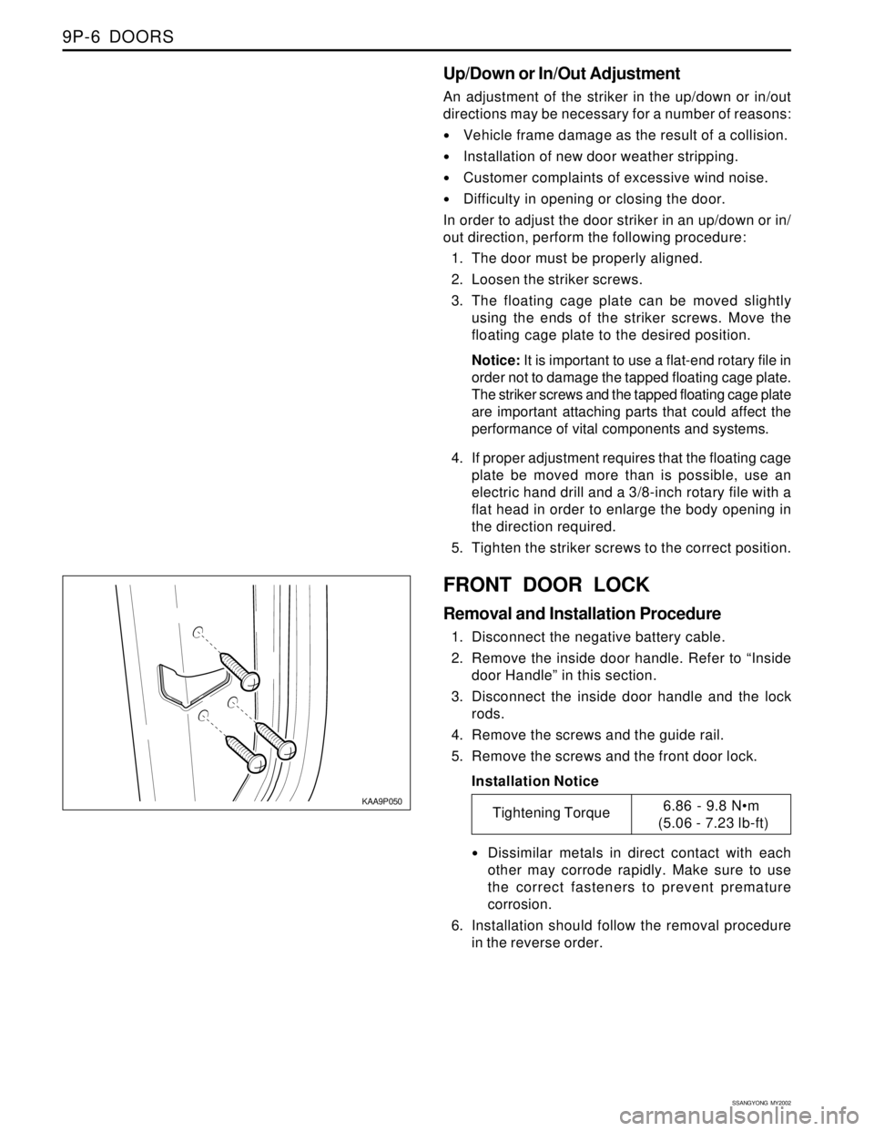
FRONT DOOR LOCK
Removal and Installation Procedure
1. Disconnect the negative battery cable.
2. Remove the inside door handle. Refer to “Inside
door Handle” in this section.
3. Disconnect the inside door handle and the lock
rods.
4. Remove the screws and the guide rail.
5. Remove the screws and the front door lock.
Installation Notice
Dissimilar metals in direct contact with each
other may corrode rapidly. Make sure to use
the correct fasteners to prevent premature
corrosion.
6. Installation should follow the removal procedure
in the reverse order.
Up/Down or In/Out Adjustment
An adjustment of the striker in the up/down or in/out
directions may be necessary for a number of reasons:
Vehicle frame damage as the result of a collision.
Installation of new door weather stripping.
Customer complaints of excessive wind noise.
Difficulty in opening or closing the door.
In order to adjust the door striker in an up/down or in/
out direction, perform the following procedure:
1. The door must be properly aligned.
2. Loosen the striker screws.
3. The floating cage plate can be moved slightly
using the ends of the striker screws. Move the
floating cage plate to the desired position.
Notice: It is important to use a flat-end rotary file in
order not to damage the tapped floating cage plate.
The striker screws and the tapped floating cage plate
are important attaching parts that could affect the
performance of vital components and systems.
4. If proper adjustment requires that the floating cage
plate be moved more than is possible, use an
electric hand drill and a 3/8-inch rotary file with a
flat head in order to enlarge the body opening in
the direction required.
5. Tighten the striker screws to the correct position.
Tightening Torque6.86 - 9.8 Nm
(5.06 - 7.23 lb-ft)
Page 1832 of 2053
SECTION 9Q
ROOF
CAUTION: Disconnect the negative battery cable before removing or installing any electrical unit or when a
tool or equipment could easily come in contact with exposed electrical terminals. Disconnecting this cable
will help prevent personal injury and damage to the vehicle. The ignition must also be in LOCK unless
otherwise noted.
TABLE OF CONTENTS
Description and Operation..................................9Q-2
Sunvisors ...........................................................9Q-2
Cat Hook............................................................9Q-2
Components Locator ...........................................9Q-3
Roof...................................................................9Q-3Unit Repair...........................................................9Q-4
Formed Headliner...............................................9Q-4
Sun Visors..........................................................9Q-4
Page 1833 of 2053
SSANGYONG MY2002
9Q-2 ROOF
DESCRIPTION AND OPERATION
SUNVISORS
The sun visors swing down in order to block out glare.
They also swing to the side when they are released
from the support. Each sun visor has a vanity mirror.
CAT HOOK
The coat hook is fastened to the headliner above the
left hand rear passenger’s seat.
Page 1835 of 2053

SSANGYONG MY2002
9Q-4 ROOF
KAA9Q030
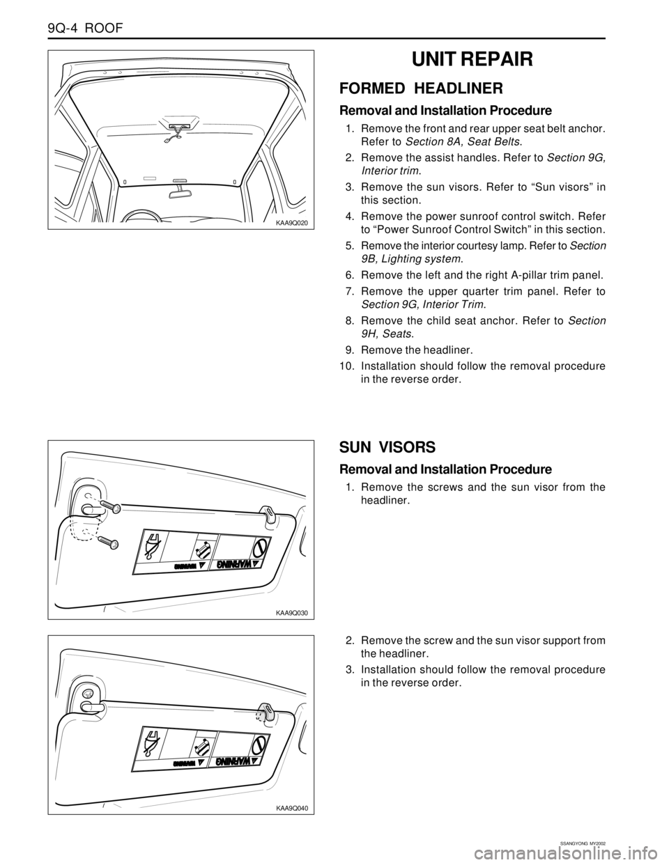
SUN VISORS
Removal and Installation Procedure
1. Remove the screws and the sun visor from the
headliner.
KAA9Q020
UNIT REPAIR
FORMED HEADLINER
Removal and Installation Procedure
1. Remove the front and rear upper seat belt anchor.
Refer to Section 8A, Seat Belts.
2. Remove the assist handles. Refer to Section 9G,
Interior trim.
3. Remove the sun visors. Refer to “Sun visors” in
this section.
4. Remove the power sunroof control switch. Refer
to “Power Sunroof Control Switch” in this section.
5. Remove the interior courtesy lamp. Refer to Section
9B, Lighting system.
6. Remove the left and the right A-pillar trim panel.
7. Remove the upper quarter trim panel. Refer to
Section 9G, Interior Trim.
8. Remove the child seat anchor. Refer to Section
9H, Seats.
9. Remove the headliner.
10. Installation should follow the removal procedure
in the reverse order.
2. Remove the screw and the sun visor support from
the headliner.
3. Installation should follow the removal procedure
in the reverse order.
KAA9Q040