Page 1472 of 2053
SSANGYONG MY2002
6C-4 POWER STEERING GEAR
DIAGNOSTIC INFORMATION AND PROCEDURES
POWER STEERING RACK AND PINION GEAR
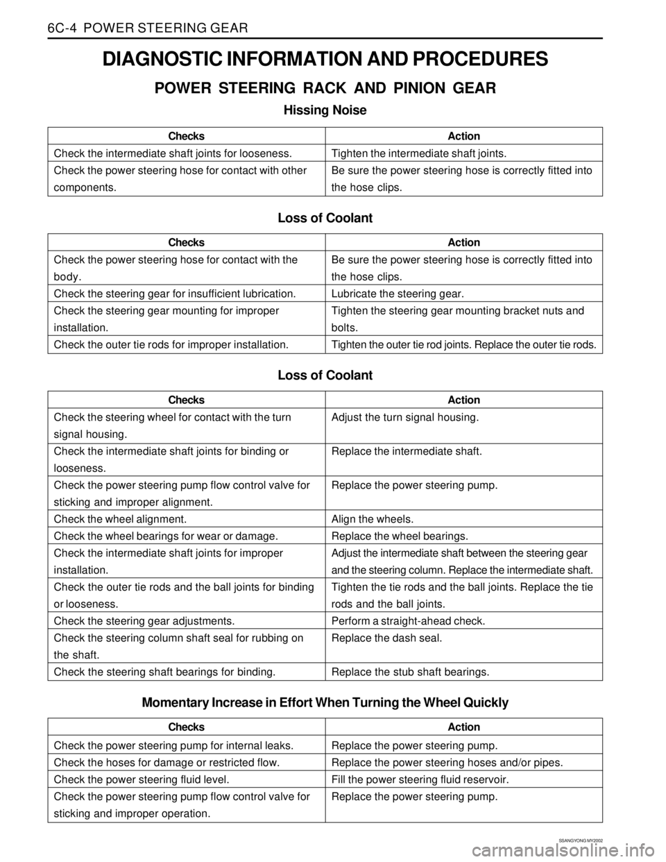
Hissing Noise
Check the intermediate shaft joints for looseness.
Check the power steering hose for contact with other
components.ChecksActionTighten the intermediate shaft joints.
Be sure the power steering hose is correctly fitted into
the hose clips.
Loss of Coolant
Check the power steering hose for contact with the
body.
Check the steering gear for insufficient lubrication.
Check the steering gear mounting for improper
installation.
Check the outer tie rods for improper installation.ChecksActionBe sure the power steering hose is correctly fitted into
the hose clips.
Lubricate the steering gear.
Tighten the steering gear mounting bracket nuts and
bolts.
Tighten the outer tie rod joints. Replace the outer tie rods.
Loss of Coolant
Check the steering wheel for contact with the turn
signal housing.
Check the intermediate shaft joints for binding or
looseness.
Check the power steering pump flow control valve for
sticking and improper alignment.
Check the wheel alignment.
Check the wheel bearings for wear or damage.
Check the intermediate shaft joints for improper
installation.
Check the outer tie rods and the ball joints for binding
or looseness.
Check the steering gear adjustments.
Check the steering column shaft seal for rubbing on
the shaft.
Check the steering shaft bearings for binding.ChecksActionAdjust the turn signal housing.
Replace the intermediate shaft.
Replace the power steering pump.
Align the wheels.
Replace the wheel bearings.
Adjust the intermediate shaft between the steering gear
and the steering column. Replace the intermediate shaft.
Tighten the tie rods and the ball joints. Replace the tie
rods and the ball joints.
Perform a straight-ahead check.
Replace the dash seal.
Replace the stub shaft bearings.
Check the power steering pump for internal leaks.
Check the hoses for damage or restricted flow.
Check the power steering fluid level.
Check the power steering pump flow control valve for
sticking and improper operation.ChecksActionReplace the power steering pump.
Replace the power steering hoses and/or pipes.
Fill the power steering fluid reservoir.
Replace the power steering pump.
Momentary Increase in Effort When Turning the Wheel Quickly
Page 1474 of 2053
SSANGYONG MY2002
6C-6 POWER STEERING GEAR
POWER STEERING RACK AND
PINION GEAR BENCH TESTING
Removal and Installation Procedure
Notice: Pressure checks or pressure and flow checks
may also be conducted using this setup.
1. Disconnect and remove the power steering gear.
Refer to “Rack and Pinion Assembly” in this
section.
2. Place the power steering gear on a bench next to
the vehicle.
3. Disconnect the pressure line at the point where the
hose connects to the pipe. Extend this line to reach
the power steering gear on the bench.
4. Disconnect the return line from the power steering
fluid reservoir. Extend this line to reach the power
steering gear on the bench.
5. Connect the power steering pipes to the power
steering gear.
6. Start the engine and allow it to idle for 10 seconds.
7. Check the power steering fluid level. Refer to
Section 6A, Power Steering System.
8. Start the engine and turn the rack and pinion stub
shaft a full turn in each direction. Hold the shaft
against each stop for 5 seconds.
9. Inspect for possible leak points. Refer to Section
6A, Power Steering System.
Installation Procedure
1. Stop the engine.
2. Disconnect the power steering pipes from the power
steering gear.
KAA6C020
3. Remove the extensions and reconnect the pressure
and return lines.
4. Install and connect the power steering gear. Refer
to “Rack and Pinion Assembly” in this section.
5. Start the engine and allow it to idle for 10 seconds.
6. Check the power steering fluid level. Refer to
Section 6A, Power Steering System.
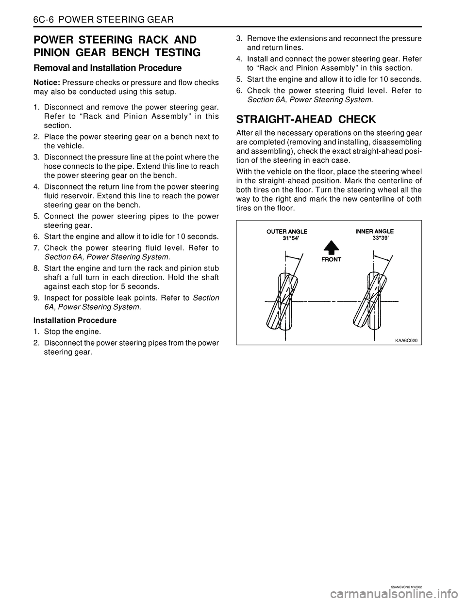
STRAIGHT-AHEAD CHECK
After all the necessary operations on the steering gear
are completed (removing and installing, disassembling
and assembling), check the exact straight-ahead posi-
tion of the steering in each case.
With the vehicle on the floor, place the steering wheel
in the straight-ahead position. Mark the centerline of
both tires on the floor. Turn the steering wheel all the
way to the right and mark the new centerline of both
tires on the floor.
Page 1475 of 2053
POWER STEERING GEAR 6C-7
SSANGYONG MY2002
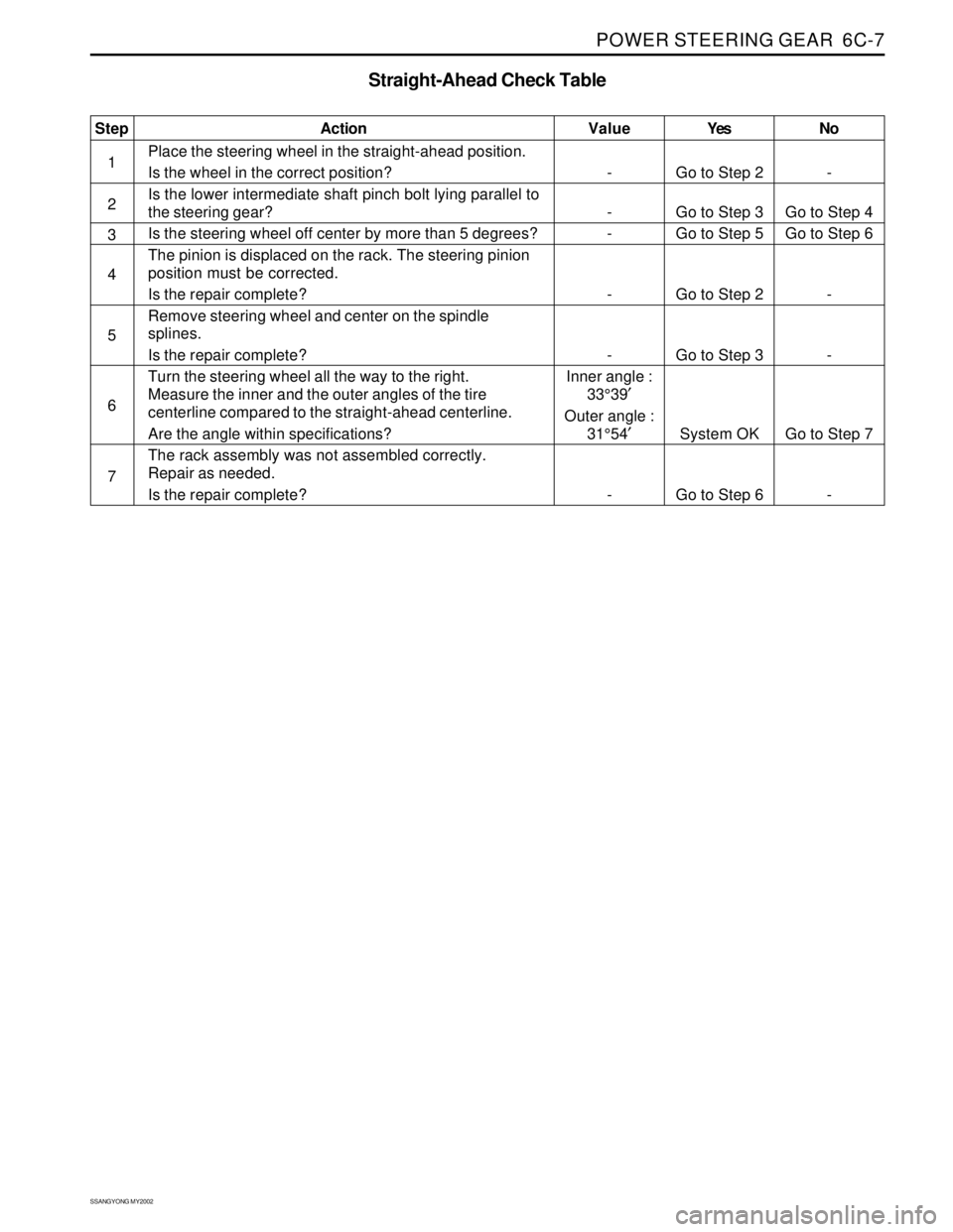
Yes
Go to Step 2
Go to Step 3
Go to Step 5
Go to Step 2
Go to Step 3
System OK
Go to Step 6No
-
Go to Step 4
Go to Step 6
-
-
Go to Step 7
- Value
-
-
-
-
-
Inner angle :
33°39′
Outer angle :
31°54′
-Step
1
2
3
4
5
6
7Action
Place the steering wheel in the straight-ahead position.
Is the wheel in the correct position?
Is the lower intermediate shaft pinch bolt lying parallel to
the steering gear?
Is the steering wheel off center by more than 5 degrees?
The pinion is displaced on the rack. The steering pinion
position must be corrected.
Is the repair complete?
Remove steering wheel and center on the spindle
splines.
Is the repair complete?
Turn the steering wheel all the way to the right.
Measure the inner and the outer angles of the tire
centerline compared to the straight-ahead centerline.
Are the angle within specifications?
The rack assembly was not assembled correctly.
Repair as needed.
Is the repair complete?
Straight-Ahead Check Table
Page 1478 of 2053
SSANGYONG MY2002
6C-10 POWER STEERING GEAR
KAA6C090
KAA6C100
KAA6C110
KAA6C080
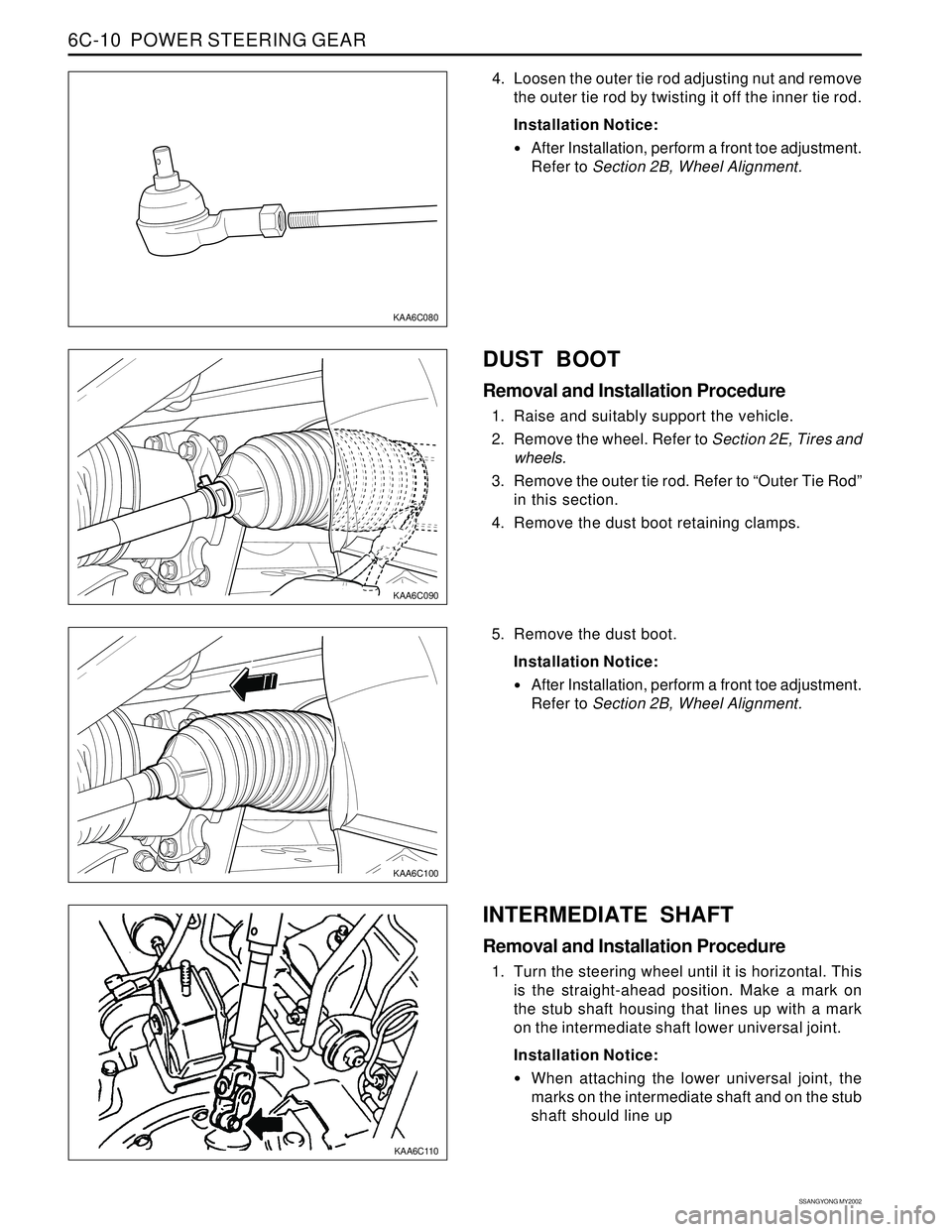
4. Loosen the outer tie rod adjusting nut and remove
the outer tie rod by twisting it off the inner tie rod.
Installation Notice:
After Installation, perform a front toe adjustment.
Refer to Section 2B, Wheel Alignment.
DUST BOOT
Removal and Installation Procedure
1. Raise and suitably support the vehicle.
2. Remove the wheel. Refer to Section 2E, Tires and
wheels.
3. Remove the outer tie rod. Refer to “Outer Tie Rod”
in this section.
4. Remove the dust boot retaining clamps.
5. Remove the dust boot.
Installation Notice:
After Installation, perform a front toe adjustment.
Refer to Section 2B, Wheel Alignment.
INTERMEDIATE SHAFT
Removal and Installation Procedure
1. Turn the steering wheel until it is horizontal. This
is the straight-ahead position. Make a mark on
the stub shaft housing that lines up with a mark
on the intermediate shaft lower universal joint.
Installation Notice:
When attaching the lower universal joint, the
marks on the intermediate shaft and on the stub
shaft should line up
Page 1482 of 2053
SSANGYONG MY2002
6C-14 POWER STEERING GEAR
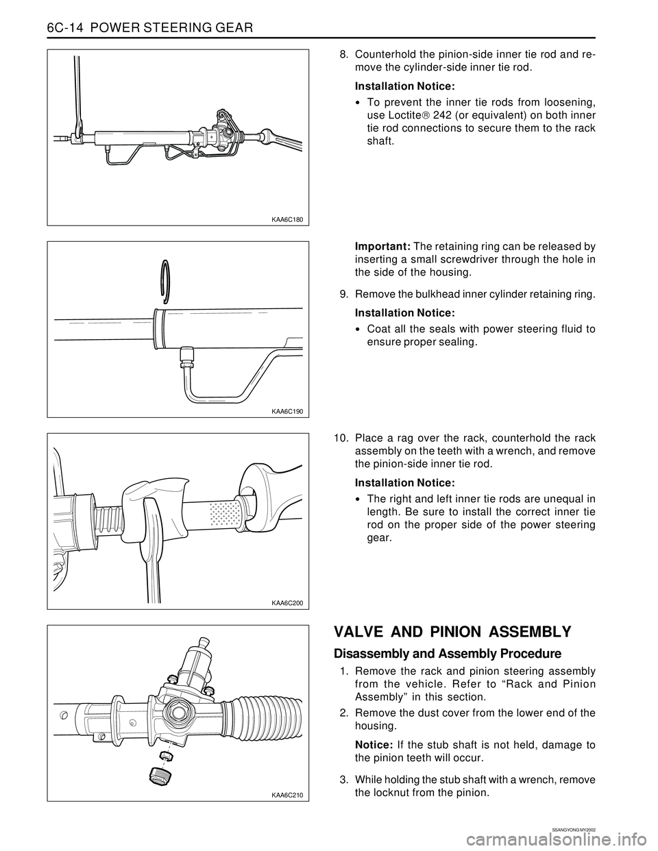
8. Counterhold the pinion-side inner tie rod and re-
move the cylinder-side inner tie rod.
Installation Notice:
To prevent the inner tie rods from loosening,
use Loctite 242 (or equivalent) on both inner
tie rod connections to secure them to the rack
shaft.
KAA6C180
KAA6C190
KAA6C210
KAA6C200
Important: The retaining ring can be released by
inserting a small screwdriver through the hole in
the side of the housing.
9. Remove the bulkhead inner cylinder retaining ring.
Installation Notice:
Coat all the seals with power steering fluid to
ensure proper sealing.
10. Place a rag over the rack, counterhold the rack
assembly on the teeth with a wrench, and remove
the pinion-side inner tie rod.
Installation Notice:
The right and left inner tie rods are unequal in
length. Be sure to install the correct inner tie
rod on the proper side of the power steering
gear.
VALVE AND PINION ASSEMBLY
Disassembly and Assembly Procedure
1. Remove the rack and pinion steering assembly
from the vehicle. Refer to “Rack and Pinion
Assembly” in this section.
2. Remove the dust cover from the lower end of the
housing.
Notice: If the stub shaft is not held, damage to
the pinion teeth will occur.
3. While holding the stub shaft with a wrench, remove
the locknut from the pinion.
Page 1487 of 2053
SECTION 6E
POWER STEERING AND COLUMN
TABLE OF CONTENTS
Description and Operation...................................6E-2
General Description.............................................6E-2
Ignition Switch Keyhole Lamp..............................6E-2
Ignition Key Reminder .........................................6E-2
Component Locator.............................................6E-3
Diagnostic Information and Procedures..............6E-4
Steering Wheel Freeplay Inspection.....................6E-4
Steering Effort Inspection.....................................6E-4
Steering Column Diagnosis..................................6E-5
Repair Instructions................................................6E-9On-Vehicle Service.................................................6E-9
Headlamp/Turn Signal Switch and Lever...............6E-9
Wiper Switch and Lever.....................................6E-10
Steering Wheel With Sir.....................................6E-10
Ignition Lock Cylinder and Switch......................6E-11
Steering Column................................................6E-12
Specifications.....................................................6E-14
Fastener Tightening Specifications.....................6E-14
Special Tools and Equipment............................6E-15
Special Tools Table............................................6E-15
Page 1488 of 2053
SSANGYONG MY2002
6E-2 POWER STEERING AND COLUMN
GENERAL DESCRIPTION
Caution: To ensure the energy-absorbing action of
the steering column, it is important to use only the
specified screws, bolts, and nuts, tightened to the
specified torque.
In addition to the steering function, the steering column
provides safety and security.
The energy-absorbing column is designed to compress
in a front-end collision to lessen the chance of driver
injury.
The ignition switch and the lock are mounted on the
column, allowing the ignition and steering operations
to be locked to inhibit theft of the car.
The column levers trigger the turn signals, the headlight
beams, and the windshield washer and wipers.
A tilt steering column uses a spherical joint to allow
the steering wheel to tilt up and down. This enables
the driver to adjust the steering wheel to a comfortable
position.
Notice: Apply a thin coat of lithium grease to all friction
points when reassembling.
The column may be disassembled and reassembled
easily.
DESCRIPTION AND OPERATION
IGNITION SWITCH KEYHOLE LAMP
For description and lamp replacement information, Re-
fer to Section 9B, Lighting Systems.
IGNITION KEY REMINDER
The ignition key reminder alerts the driver that the key
is still in the ignition when the driver attempts to exit
the vehicle.
An internal switch in the ignition lock cylinder supplies
battery voltage to the reminder chime module when all
of the following conditions are true:
•The key is in the ignition switch.
The ignition is OFF.
The driver’s door is open.
For information on removal and installation of the re-
minder chime module, Refer to Section 9E, Instrumen-
tation/Driver Information.
Page 1489 of 2053
POWER STEERING AND COLUMN 6E-3
SSANGYONG MY2002
COMPONENT LOCATOR
KAA6E010
1 Driver Airbag Module
2 Steering Wheel Nut
3 Steering Wheel
4 Lower Steering Column Cover
5 Lower Steering Column Cover Screw
6 Steering Column Upper Mounting Bolt7 Steering Column Lower Mounting Nut
8 Intermediate Shaft Upper Pinch Bolt
9 Intermediate Shaft
10 Steering Column
11 Upper Steering Column Cover
12 Headlamp/Turn Signal Switch and Lever