1997 SSANGYONG KORANDO air condition
[x] Cancel search: air conditionPage 1771 of 2053
WATERLEAKS 9I-3
SSANGYONG MY2002
DIAGNOSIS
WATERLEAK DIAGNOSIS
The repair of waterleaks in the body requires proper
testing and diagnosis. Repair waterleaks by adjusting
the misaligned parts and using the proper repair materi-
als. First, determine what conditions cause the leak.
For example, the leak may occur only when the vehicle
is parked on an incline, or water may appear only in
the spare tire compartment. Second, test the area for
the source of the leak using the following testing
methods. If the general leak area is found, determine
the exact entry point of the leak by using a water hose
or an air hose. If the general leak area is not obvious,
use the watertest stands to determine the area of the
leak. It may be necessary to remove some interior trim
panels or some parts in order to locate the leaks.
Important: It is necessary to find the origin of all the
leaks before making any repairs. Random repairs may
stop the leak only temporarily and may make future
repairs more difficult. Continue localized testing in the
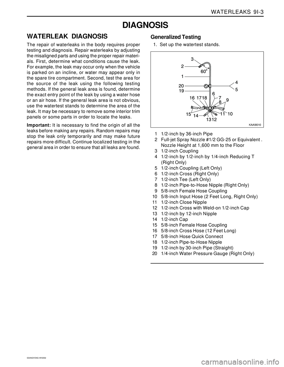
general area in order to ensure that all leaks are found.1 1/2-inch by 36-inch Pipe
2 Full-jet Spray Nozzle #1/2 GG-25 or Equivalent .
Nozzle Height at 1,600 mm to the Floor
3 1/2-inch Coupling
4 1/2-inch by 1/2-inch by 1/4-inch Reducing T
(Right Only)
5 1/2-inch Coupling (Left Only)
6 1/2-inch Cross (Right Only)
7 1/2-inch Tee (Left Only)
8 1/2-inch Pipe-to-Hose Nipple (Right Only)
9 5/8-inch Female Hose Coupling
10 5/8-inch Input Hose (2 Feet Long, Right Only)
11 1/2-inch Close Nipple
12 1/2-inch Cross with Weld-on 1/2-inch Cap
13 1/2-inch by 12-inch Nipple
14 1/2-inch Cap
15 5/8-inch Female Hose Coupling
16 5/8-inch Cross Hose (12 Feet Long)
17 5/8-inch Hose Quick Connect
18 1/2-inch Pipe-to-Hose Nipple
19 1/2-inch by 30-inch Pipe (Straight)
20 1/4-inch Water Pressure Gauge (Right Only)
KAA9I010
Generalized Testing
1. Set up the watertest stands.
Page 1777 of 2053
SSANGYONG MY2002
9J-2 WINDNOISE
DIAGNOSIS
WINDNOISE DIAGNOSIS
Caution: An assistant should drive the vehicle while
the technician checks for the location of the wind-
noise, in order to prevent personal injury or vehicle
damage.
A test drive in the vehicle is necessary to accurately
determine the location of the windnoise. Often there is
a primary leak and secondary leaks. Failure to repair
all leaks will only reduce the windnoise, not eliminate
it.
During the test drive the technician should bring the
following items to aid in determining the location of
the windnoise.
•A mechanics stethoscope or vacuum hose
Masking tape
Strip caulk
A china marking pencil
A screwdriver
Perform the following steps in order to conduct the
road test:
1. Choose a route that includes smooth straight
streets that run in all four directions (north, south,
east, and west).
2. Choose streets with little traffic or noise that would
interfere with the test.
3. Drive the vehicle at the speeds at which the noise
was noticed by the customer or until the noise is
produced. Do not exceed legal speed limits.
4. The windnoise is external if any of the following
conditions occur:
The windnoise is caused by the wind.
The windnoise can be heard with the door glass
lowered and while the vehicle is being driven.
The windnoise is eliminated when tape is placed
over various moldings and gaps.5. Internal windnoise is air leaving the vehicle and
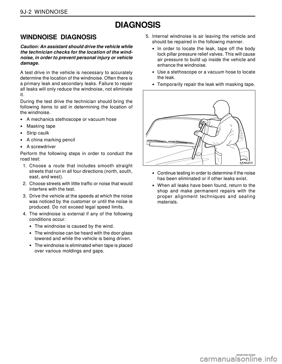
should be repaired in the following manner.
In order to locate the leak, tape off the body
lock pillar pressure relief valves. This will cause
air pressure to build up inside the vehicle and
enhance the windnoise.
Use a stethoscope or a vacuum hose to locate
the leak.
Temporarily repair the leak with masking tape.
Continue testing in order to determine if the noise
has been eliminated or if other leaks exist.
When all leaks have been found, return to the
shop and make permanent repairs with the
proper alignment techniques and sealing
materials.
KAA9J010
Page 1778 of 2053
WINDNOISE 9J-3
SSANGYONG MY2002
MAINTENANCE AND REPAIR
ON-VEHICLE SERVICE
WINDNOISE REPAIR
Windnoise leak repairs are very similar to waterleak
repairs. Refer to Section 9I, Waterleaks. The actual
procedure depends on the type of seal being repaired.
Leaks around the door opening weatherstrips do not
al-ways indicate a faulty weatherstrip. A door or window
adjustment may resolve the condition. Refer to Section
9P, Doors or Section 9L, Glass and Mirrors.
Page 1811 of 2053
FRAME AND UNDERBODY 9N-9
SSANGYONG MY2002
GENERAL DESCRIPTION AND SYSTEM OPERATION
GENERAL BODY CONSTRUCTION
This vehicle is constructed with a unitized body which
in-corporates integral front and rear frame side rails.
The front suspension lower control arms are bolted to
and retained by supports, one each on the right and
left sides. The front suspension lower control arm
supports are attached to the underbody with three bolts
at two locations. The engine is bolted to the integral
front side rails. The suspension strut towers must be
dimensionally correct in relation to the remainder of
the underbody in order to maintain specified
suspension strut and caster/camber angles.
Since the individual underbody parts contribute directly
to the overall strength of the body, it is essential to
observe proper welding techniques during servicerepair operations. The underbody parts should be
properly sealed and rustproofed whenever body repair
operations destroy or damage the original sealing and
rustproofing. When rustproofing critical underbody
parts, use a good-quality type of air-dry primer, such
as a corrosion-resistant chromate or an equivalent
material. Combination-type primer/surfacers are not
recommended.
ENGINE UNDER COVERS
The engine under covers are molded pieces of plastic
that serve as shields for the underside of the engine.
The covers help protect the engine from small rocks,
gravel and other objects that would otherwise come
into contact with the engine during normal driving
conditions.
Page 1868 of 2053
2-4 2-4 2-4 2-4
2-4
ELECTRICAL WIRING DIAGRAMS ELECTRICAL WIRING DIAGRAMSELECTRICAL WIRING DIAGRAMS ELECTRICAL WIRING DIAGRAMS
ELECTRICAL WIRING DIAGRAMS
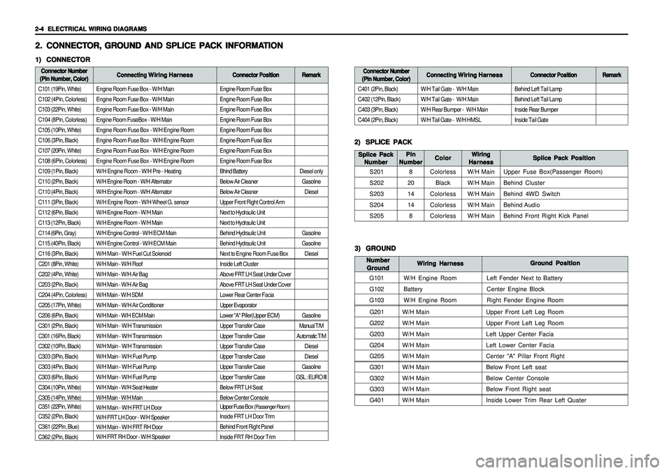
Engine Room Fuse Box - W/H Main
Engine Room Fuse Box - W/H Main
Engine Room Fuse Box - W/H Main
Engine Room FuseBox - W/H Main
Engine Room Fuse Box - W/H Engine Room
Engine Room Fuse Box - W/H Engine Room
Engine Room Fuse Box - W/H Engine Room
Engine Room Fuse Box - W/H Engine Room
W/H Engine Room - W/H Pre - Heating
W/H Engine Room - W/H Alternator
W/H Engine Room - W/H Alternator
W/H Engine Room - W/H Wheel G. sensor
W/H Engine Room - W/H Main
W/H Engine Room - W/H Main
W/H Engine Control - W/H ECM Main
W/H Engine Control - W/H ECM Main
W/H Main - W/H Fuel Cut Solenoid
W/H Main - W/H Roof
W/H Main - W/H Air Bag
W/H Main - W/H Air Bag
W/H Main - W/H SDM
W/H Main - W/H Air Conditioner
W/H Main - W/H ECM Main
W/H Main - W/H Transmission
W/H Main - W/H Transmission
W/H Main - W/H Transmission
W/H Main - W/H Fuel Pump
W/H Main - W/H Fuel Pump
W/H Main - W/H Fuel Pump
W/H Main - W/H Seat Heater
W/H Main - W/H Main
W/H Main - W/H FRT LH Door
W/H FRT LH Door - W/H Speaker
W/H Main - W/H FRT RH Door
W/H FRT RH Door - W/H Speaker
G201W/H Main Upper Front Left Leg Room
G202W/H Main Upper Front Left Leg Room
G203W/H Main Left Upper Center Facia
G204W/H Main Left Lower Center Facia
G205W/H Main Center "A" Pillar Front Right
G301W/H Main Below Front Left seat
G302W/H Main Below Center Console
G303W/H Main Below Front Right seat
G401W/H Main Inside Lower Trim Rear Left Quater
Engine Room Fuse Box
Engine Room Fuse Box
Engine Room Fuse Box
Engine Room Fuse Box
Engine Room Fuse Box
Engine Room Fuse Box
Engine Room Fuse Box
Engine Room Fuse Box
Bhind Battery
Below Air Cleaner
Below Air Cleaner
Upper Front Right Control Arm
Next to Hydraulic Unit
Next to Hydraulic Unit
Behind Hydraulic Unit
Behind Hydraulic Unit
Next to Engine Room Fuse Box
Inside Left Cluster
Above FRT LH Seat Under Cover
Above FRT LH Seat Under Cover
Lower Rear Center Facia
Upper Evaporator
Lower "A" Piller(Upper ECM)
Upper Transfer Case
Upper Transfer Case
Upper Transfer Case
Upper Transfer Case
Upper Transfer Case
Upper Transfer Case
Below FRT LH Seat
Below Center Console
Upper Fuse Box
(Passenger Room)
Inside FRT LH Door Trim
Behind Front Right Panel
Inside FRT RH Door Trim
2. 2.2. 2.
2.
CONNECT CONNECTCONNECT CONNECT
CONNECT
OR, OR,OR, OR,
OR,
GR GR GR GR
GR
OUND AND SPLICE PA OUND AND SPLICE PAOUND AND SPLICE PA OUND AND SPLICE PA
OUND AND SPLICE PA
CK INFORMA CK INFORMACK INFORMA CK INFORMA
CK INFORMA
TION TIONTION TION
TION1) 1)1) 1)
1)
CONNECTOR CONNECTORCONNECTOR CONNECTOR
CONNECTORConnector Number Connector NumberConnector Number Connector Number
Connector Number
(Pin Number, Color) (Pin Number, Color)(Pin Number, Color) (Pin Number, Color)
(Pin Number, Color)Connecting Connecting Connecting Connecting
Connecting
Wiring Harness Wiring HarnessWiring Harness Wiring Harness
Wiring Harness
Connector Position Connector PositionConnector Position Connector Position
Connector Position
C101 (19Pin, White)
C102 (4Pin, Colorless)
C103 (22Pin, White)
C104 (8Pin, Colorless)
C105 (10Pin, White)
C106 (3Pin, Black)
C107 (20Pin, White)
C108 (6Pin, Colorless)
C109 (1Pin, Black)
C110 (2Pin, Black)
C110 (4Pin, Black)
C111 (3Pin, Black)
C112 (6Pin, Black)
C113 (12Pin, Black)
C114 (6Pin, Gray)
C115 (40Pin, Black)
C116 (3Pin, Black)
C201 (8Pin, White)
C202 (4Pin, White)
C203 (2Pin, Black)
C204 (4Pin, Colorless)
C205 (17Pin, White)
C206 (6Pin, Black)
C301 (2Pin, Black)
C301 (16Pin, Black)
C302 (10Pin, Black)
C303 (3Pin, Black)
C303 (4Pin, Black)
C303 (6Pin, Black)
C304 (10Pin, White)
C305 (14Pin, White)
C351 (22Pin, White)
C352 (2Pin, Black)
C361 (22Pin, Blue)
C362 (2Pin, Black)
2) 2)2) 2)
2)
SPLICE PACK SPLICE PACKSPLICE PACK SPLICE PACK
SPLICE PACK
S201
S202
S203
S204
S205Splice Pack Position Splice Pack PositionSplice Pack Position Splice Pack Position
Splice Pack Position Wiring WiringWiring Wiring
Wiring
Harness HarnessHarness Harness
Harness Color ColorColor Color
Color Splice Pack Splice PackSplice Pack Splice Pack
Splice Pack
Number NumberNumber Number
Number
Colorless
Black
Colorless
Colorless
ColorlessW/H Main
W/H Main
W/H Main
W/H Main
W/H MainUpper Fuse Box(Passenger Room)
Behind Cluster
Behind 4WD Switch
Behind Audio
Behind Front Right Kick Panel
Remark RemarkRemark Remark
Remark
Diesel only
Gasoline
Diesel
Gasoline
Gasoline
Diesel
Gasoline
Manual T/M
Automatic T/M
Diesel
Diesel
Gasoline
GSL : EURO IIIBehind Left Tail Lamp
Behind Left Tail Lamp
Inside Rear Bumper
Inside Tail Gate
Connector Number Connector NumberConnector Number Connector Number
Connector Number
(Pin Number, Color) (Pin Number, Color)(Pin Number, Color) (Pin Number, Color)
(Pin Number, Color)Connecting Connecting Connecting Connecting
Connecting
Wiring Harness Wiring HarnessWiring Harness Wiring Harness
Wiring Harness
Connector Position Connector PositionConnector Position Connector Position
Connector Position
C401 (2Pin, Black)
C402 (12Pin, Black)
C403 (3Pin, Black)
C404 (2Pin, Black)W/H Tail Gate - W/H Main
W/H Tail Gate - W/H Main
W/H Rear Bumper - W/H Main
W/H Tail Gate - W/H HMSL
Remark RemarkRemark Remark
Remark
3) 3)3) 3)
3)
GROUND GROUNDGROUND GROUND
GROUND
G101
G102
G103Ground Position Ground PositionGround Position Ground Position
Ground Position
Wiring Harness Wiring HarnessWiring Harness Wiring Harness
Wiring Harness Number NumberNumber Number
Number
Ground GroundGround Ground
Ground
W/H Engine Room
Battery
W/H Engine RoomLeft Fender Next to Battery
Center Engine Block
Right Fender Engine Room
Pin PinPin Pin
Pin
Number NumberNumber Number
Number
8
20
14
14
8
Page 1875 of 2053
ELECTRICAL WIRING DIAGRAMS ELECTRICAL WIRING DIAGRAMSELECTRICAL WIRING DIAGRAMS ELECTRICAL WIRING DIAGRAMS
ELECTRICAL WIRING DIAGRAMS
2-11 2-11 2-11 2-11
2-11
7) 7)7) 7)
7)
W/H AIR-CONDITIONER W/H AIR-CONDITIONERW/H AIR-CONDITIONER W/H AIR-CONDITIONER
W/H AIR-CONDITIONER
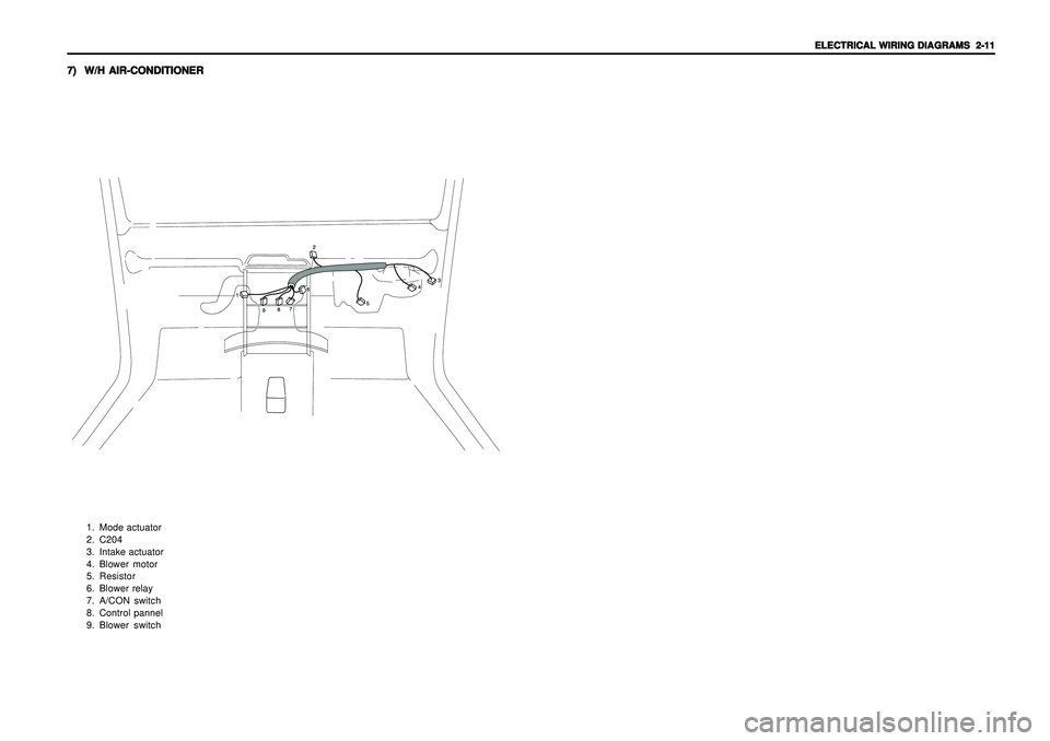
1. Mode actuator
2. C204
3. Intake actuator
4. Blower motor
5. Resistor
6. Blower relay
7. A/CON switch
8. Control pannel
9. Blower switch
Page 1897 of 2053

9. 9. 9. 9.
9.
ABS (ANTI-LOCK BRAKE SYSTEM) ABS (ANTI-LOCK BRAKE SYSTEM)ABS (ANTI-LOCK BRAKE SYSTEM) ABS (ANTI-LOCK BRAKE SYSTEM)
ABS (ANTI-LOCK BRAKE SYSTEM)
....................................................................................... .............................................................................................................................................................................. .......................................................................................
.......................................................................................
5-62 5-62 5-62 5-62
5-62
10. 10.10. 10.
10.
ABS/ABD (A ABS/ABD (AABS/ABD (A ABS/ABD (A
ABS/ABD (A
UT UTUT UT
UT
OMA OMAOMA OMA
OMA
TIC BRAKE DIFFERENTIAL LOCK): TIC BRAKE DIFFERENTIAL LOCK):TIC BRAKE DIFFERENTIAL LOCK): TIC BRAKE DIFFERENTIAL LOCK):
TIC BRAKE DIFFERENTIAL LOCK):
DIESEL DIESEL DIESEL DIESEL
DIESEL
...................................... ............................................................................ ......................................
......................................
5-64 5-64 5-64 5-64
5-64
1) INDICATOR, RELAY (ABD, MOTOR, VALVE), HYDRAULIC MODULATOR.................................................... 5-64
2) STOP LAMP SWITCH, ACCELERATION SENSOR, WHEEL SPEED SENSOR, DIAGNOSIS..................... 5-66
11. 11.11. 11.
11.
ABS/ABD (A ABS/ABD (AABS/ABD (A ABS/ABD (A
ABS/ABD (A
UT UTUT UT
UT
OMA OMAOMA OMA
OMA
TIC BRAKE DIFFERENTIAL LOCK): TIC BRAKE DIFFERENTIAL LOCK):TIC BRAKE DIFFERENTIAL LOCK): TIC BRAKE DIFFERENTIAL LOCK):
TIC BRAKE DIFFERENTIAL LOCK):
GASOLINE GASOLINE GASOLINE GASOLINE
GASOLINE
................................ ................................................................ ................................
................................
5-68 5-68 5-68 5-68
5-68
1) INDICATOR, RELAY (ABD, MOTOR, VALVE), HYDRAULIC MODULATOR.................................................... 5-68
2) STOP LAMP SWITCH, ACCELERATION SENSOR, WHEEL SPEED SENSOR, DIAGNOSIS..................... 5-70
12. 12.12. 12.
12.
ABS/ABD (A ABS/ABD (AABS/ABD (A ABS/ABD (A
ABS/ABD (A
UT UTUT UT
UT
OMA OMAOMA OMA
OMA
TIC BRAKE DIFFERENTIAL LOCK): TIC BRAKE DIFFERENTIAL LOCK):TIC BRAKE DIFFERENTIAL LOCK): TIC BRAKE DIFFERENTIAL LOCK):
TIC BRAKE DIFFERENTIAL LOCK):
EUR EUR EUR EUR
EUR
O III O IIIO III O III
O III
.................................... ........................................................................ ....................................
....................................
5-72 5-72 5-72 5-72
5-72
-ATTACHED EBCM-................................................................................................................................................... 5-72
13. 13.13. 13.
13.
TCCU TCCUTCCU TCCU
TCCU
........................................................................................................................................... ........................................................................................................................................... ........................................................................................................................................... ...........................................................................................................................................
...........................................................................................................................................
5-74 5-74 5-74 5-74
5-74
1) INDICATOR, DIAGNOSIS..................................................................................................................................... 5-74
2) 4WD SWITCH, SPEED SENSOR & CLUTCH COIL, SHIFT MOTOR, LOCKING HUB SOLENOID ............ 5-76
14. 14.14. 14.
14.
TOD (TORQUE ON DEMAND) TOD (TORQUE ON DEMAND)TOD (TORQUE ON DEMAND) TOD (TORQUE ON DEMAND)
TOD (TORQUE ON DEMAND)
................................................................................................. .................................................................................................................................................................................................. .................................................................................................
.................................................................................................
5-78 5-78 5-78 5-78
5-78
1) 4WD SWITCH, INDICATOR, DIAGNOSIS, SHIFT MOTOR.............................................................................. 5-78
2) SPEED SENSOR & CLUTCH (COIL, CLUTCH SW(M/T) & NEUTRAL RELAY (A/T)) .................................... 5-80
15. 15.15. 15.
15.
MANUAL AIR CONDITIONING SYSTEM : DIESEL MANUAL AIR CONDITIONING SYSTEM : DIESELMANUAL AIR CONDITIONING SYSTEM : DIESEL MANUAL AIR CONDITIONING SYSTEM : DIESEL
MANUAL AIR CONDITIONING SYSTEM : DIESEL
................................................................. .................................................................................................................................. .................................................................
.................................................................
5-82 5-82 5-82 5-82
5-82
1) CONDNSER FAN MOTOR, THERMO SWITCH, COMPRESOR, THERMO AMP ............................................ 5-82MANUAL AIR CONDITIONING SYSTEM : GASOLINE MANUAL AIR CONDITIONING SYSTEM : GASOLINEMANUAL AIR CONDITIONING SYSTEM : GASOLINE MANUAL AIR CONDITIONING SYSTEM : GASOLINE
MANUAL AIR CONDITIONING SYSTEM : GASOLINE
........................................................... ...................................................................................................................... ...........................................................
...........................................................
5-84 5-84 5-84 5-84
5-841) CONDNSER FAN MOTOR(LH/RH), COMPRESOR, THERMO AMP ................................................................. 5-84
2) BLOWER MOTOR CIRCUIT................................................................................................................................. 5-86
3) CONTROL PANEL, INTAKE ACTUATOR, MODE ACTUATOR......................................................................... 5-88
16. 16.16. 16.
16.
AIR BAG (SDM : SENSING & DIAGNOSIS MODULE) AIR BAG (SDM : SENSING & DIAGNOSIS MODULE)AIR BAG (SDM : SENSING & DIAGNOSIS MODULE) AIR BAG (SDM : SENSING & DIAGNOSIS MODULE)
AIR BAG (SDM : SENSING & DIAGNOSIS MODULE)
........................................................... ...................................................................................................................... ...........................................................
...........................................................
5-90 5-90 5-90 5-90
5-90
17. 17.17. 17.
17.
SEA SEASEA SEA
SEA
T BEL T BELT BEL T BEL
T BEL
T & T & T & T &
T &
TENSION REDUCER TENSION REDUCERTENSION REDUCER TENSION REDUCER
TENSION REDUCER
........................................................................................ ................................................................................................................................................................................ ........................................................................................
........................................................................................
5-92 5-92 5-92 5-92
5-92
18. 18.18. 18.
18.
CLUSTER CLUSTERCLUSTER CLUSTER
CLUSTER
.................................................................................................................................... .................................................................................................................................... .................................................................................................................................... ....................................................................................................................................
....................................................................................................................................
5-94 5-94 5-94 5-94
5-94
1) VSS(VEHICLE SPEED SENSOR), METER(SPEEDO, TACHO) & GAUGE(FUEL, TEMPERATURE)
- DIESEL................................................................................................................................................................. 5-94
Page 1972 of 2053
5-82 5-82 5-82 5-82
5-82
ELECTRICAL WIRING DIAGRAMS ELECTRICAL WIRING DIAGRAMSELECTRICAL WIRING DIAGRAMS ELECTRICAL WIRING DIAGRAMS
ELECTRICAL WIRING DIAGRAMS
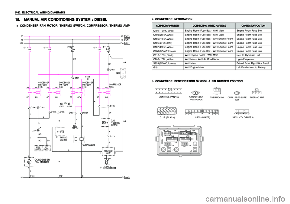
Engine Room Fuse Box - W/H Main
Engine Room Fuse Box - W/H Main
Engine Room Fuse Box - W/H Engine Room
Engine Room Fuse Box - W/H Engine Room
Engine Room Fuse Box - W/H Engine Room
Engine Room Fuse Box - W/H Engine Room
W/H Engine Room - W/H Main
W/H Main - W/H Air Conditioner
W/H Main
W/H Engine Main
a. a.a. a.
a.
CONNECTOR INFORMATION CONNECTOR INFORMATIONCONNECTOR INFORMATION CONNECTOR INFORMATION
CONNECTOR INFORMATION
b. b.b. b.
b.
CONNECTOR IDENTIFICATION SYMBOL & PIN NUMBER POSITION CONNECTOR IDENTIFICATION SYMBOL & PIN NUMBER POSITIONCONNECTOR IDENTIFICATION SYMBOL & PIN NUMBER POSITION CONNECTOR IDENTIFICATION SYMBOL & PIN NUMBER POSITION
CONNECTOR IDENTIFICATION SYMBOL & PIN NUMBER POSITION
CONDENSOR
FAN MOTOR CONTROL PANNEL
DUAL PRESSURE
SW
THERMO SW
C113 (BLACK)
15. 15.15. 15.
15.
MANUAL AIR CONDITIONING SYSTEM : DIESEL MANUAL AIR CONDITIONING SYSTEM : DIESELMANUAL AIR CONDITIONING SYSTEM : DIESEL MANUAL AIR CONDITIONING SYSTEM : DIESEL
MANUAL AIR CONDITIONING SYSTEM : DIESEL1) 1)1) 1)
1)
CONDENSER FAN MOTOR, THERMO SWITCH, COMPRESSOR, THERMO AMP CONDENSER FAN MOTOR, THERMO SWITCH, COMPRESSOR, THERMO AMPCONDENSER FAN MOTOR, THERMO SWITCH, COMPRESSOR, THERMO AMP CONDENSER FAN MOTOR, THERMO SWITCH, COMPRESSOR, THERMO AMP
CONDENSER FAN MOTOR, THERMO SWITCH, COMPRESSOR, THERMO AMP
THERMO AMP
C205 (WHITE)
S205 (COLORLESS)
C101 (19Pin, White)
C103 (22Pin,White)
C105 (10Pin,White)
C106 (3Pin,Black)
C107 (20Pin,White)
C108 (6Pin,Colorless)
C113 (12Pin,Black)
C205 (17Pin,White)
S205 (8Pin,Colorless)
G101CONNECTOR(NUMBER) CONNECTOR(NUMBER)CONNECTOR(NUMBER) CONNECTOR(NUMBER)
CONNECTOR(NUMBER)
CONNECTING. WIRING HARNESS CONNECTING. WIRING HARNESSCONNECTING. WIRING HARNESS CONNECTING. WIRING HARNESS
CONNECTING. WIRING HARNESS
CONNECTOR POSITION CONNECTOR POSITIONCONNECTOR POSITION CONNECTOR POSITION
CONNECTOR POSITION
Engine Room Fuse Box
Engine Room Fuse Box
Engine Room Fuse Box
Engine Room Fuse Box
Engine Room Fuse Box
Engine Room Fuse Box
Next to Hydraulic Unit
Upper Evaporator
Behind Front Right Kick Panel
Left Fender Next to Battery