1997 SSANGYONG KORANDO air condition
[x] Cancel search: air conditionPage 1627 of 2053
SSANGYONG MY2002
8B-44 SUPPLEMENTAL RESTRAINTS SYSTEM
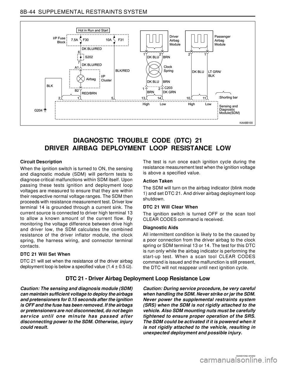
Circuit Description
When the ignition switch is turned to ON, the sensing
and diagnostic module (SDM) will perform tests to
diagnose critical malfunctions within SDM itself. Upon
passing these tests ignition and deployment loop
voltages are measured to ensure that they are within
their respective normal voltage ranges. The SDM then
proceeds with resistance measurement test. Driver low
terminal 14 is grounded through a current sink. The
current source is connected to driver high terminal 13
to allow a known amount of the current flow. By
monitoring the voltage difference between drive high
and driver low, the SDM calculates the combined
resistance of the driver inflator module, the clock
spring, the harness wiring, and connector terminal
contacts.
DTC 21 Will Set When
DTC 21 will set when the resistance of the driver airbag
deployment loop is below a specified value (1.4 ± 0.5 Ω).
DIAGNOSTIC TROUBLE CODE (DTC) 21
DRIVER AIRBAG DEPLOYMENT LOOP RESISTANCE LOW
The test is run once each ignition cycle during the
resistance measurement test when the ignition voltage
is above a specified value.
Action Taken
The SDM will turn on the airbag indicator (blink mode
1) and set DTC 21. And driver airbag deployment loop
shutdown.
DTC 21 Will Clear When
The ignition switch is turned OFF or the scan tool
CLEAR CODES command is received.
Diagnostic Aids
All intermittent condition is likely to be the caused by
a poor connection from the driver airbag to the clock
spring or SDM terminal 13 or 14. The test for this DTC
is run only while the airbag indicator is performing the
start-up test. When a scan tool CLEAR CODES
command is issued and the malfunction is still present,
the DTC will not reappear until next ignition cycle.
KAA8B100
DTC 21 - Driver Airbag Deployment Loop Resistance Low
Caution: The sensing and diagnosis module (SDM)
can maintain sufficient voltage to deploy the airbags
and pretensioners for 0.15 seconds after the ignition
is OFF and the fuse has been removed. If the airbags
or pretensioners are not disconnected, do not begin
service until one minute has passed after
disconnecting power to the SDM. Otherwise, injury
could result.Caution: During service procedure, be very careful
when handling the SDM. Never strike or jar the SDM.
Never power the supplemental restraints system
(SRS) when the SDM is not rigidly attached to the
vehicle. Also SDM mounting nuts must be carefully
tightened to ensure proper operation of the SRS.
The SDM could be activated if it is powered when it
is not rigidly attached to the vehicle, resulting in
unexpected deployment and possible injury.
Page 1630 of 2053
SSANGYONG MY2002
8B-48 SUPPLEMENTAL RESTRAINTS SYSTEM
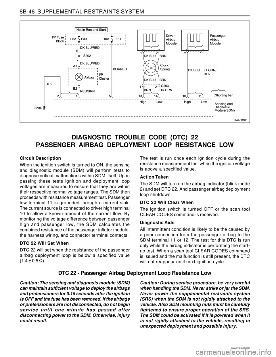
Circuit Description
When the ignition switch is turned to ON, the sensing
and diagnostic module (SDM) will perform tests to
diagnose critical malfunctions within SDM itself. Upon
passing these tests ignition and deployment loop
voltages are measured to ensure that they are within
their respective normal voltage ranges. The SDM then
proceeds with resistance measurement test. Passenger
low terminal 11 is grounded through a current sink.
The current source is connected to driver high terminal
10 to allow a known amount of the current flow. By
monitoring the voltage difference between passenger
high and passenger low, the SDM calculates the
combined resistance of the passenger inflator module,
the harness wiring, and connector terminal contacts.
DTC 22 Will Set When
DTC 22 will set when the resistance of the passenger
airbag deployment loop is below a specified value
(1.4 ± 0.5 Ω).
DIAGNOSTIC TROUBLE CODE (DTC) 22
PASSENGER AIRBAG DEPLOYMENT LOOP RESISTANCE LOW
The test is run once each ignition cycle during the
resistance measurement test when the ignition voltage
is above a specified value.
Action Taken
The SDM will turn on the airbag indicator (blink mode
2) and set DTC 22. And passenger airbag deployment
loop shutdown.
DTC 22 Will Clear When
The ignition switch is turned OFF or the scan tool
CLEAR CODES command is received.
Diagnostic Aids
All intermittent condition is likely to be the caused by
a poor connection from the passenger airbag to the
SDM terminal 11 or 12. The test for this DTC is run
only while the airbag indicator is performing the start-
up test. When a scan tool CLEAR CODES command
is issued and the malfunction is still present, the DTC
will not reappear until next ignition cycle.
KAA8B100
DTC 22 - Passenger Airbag Deployment Loop Resistance Low
Caution: The sensing and diagnosis module (SDM)
can maintain sufficient voltage to deploy the airbags
and pretensioners for 0.15 seconds after the ignition
is OFF and the fuse has been removed. If the airbags
or pretensioners are not disconnected, do not begin
service until one minute has passed after
disconnecting power to the SDM. Otherwise, injury
could result.Caution: During service procedure, be very careful
when handling the SDM. Never strike or jar the SDM.
Never power the supplemental restraints system
(SRS) when the SDM is not rigidly attached to the
vehicle. Also SDM mounting nuts must be carefully
tightened to ensure proper operation of the SRS.
The SDM could be activated if it is powered when it
is not rigidly attached to the vehicle, resulting in
unexpected deployment and possible injury.
Page 1632 of 2053
SSANGYONG MY2002
8B-50 SUPPLEMENTAL RESTRAINTS SYSTEM
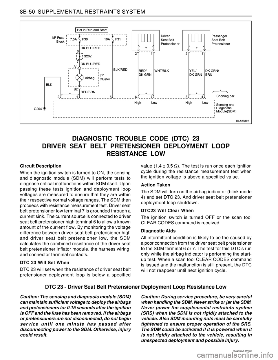
Circuit Description
When the ignition switch is turned to ON, the sensing
and diagnostic module (SDM) will perform tests to
diagnose critical malfunctions within SDM itself. Upon
passing these tests ignition and deployment loop
voltages are measured to ensure that they are within
their respective normal voltage ranges. The SDM then
proceeds with resistance measurement test. Driver seat
belt pretensioner low terminal 7 is grounded through a
current sink. The current source is connected to driver
seat belt pretensioner high terminal 6 to allow a known
amount of the current flow. By monitoring the voltage
difference between driver seat belt pretensioner high
and driver seat belt pretensioner low, the SDM
calculates the combined resistance of the driver seat
belt pretensioner inflator module, the harness wiring,
and connector terminal contacts.
DTC 23 Will Set When
DTC 23 will set when the resistance of driver seat belt
pretensioner deployment loop is below a specified
DIAGNOSTIC TROUBLE CODE (DTC) 23
DRIVER SEAT BELT PRETENSIONER DEPLOYMENT LOOP
RESISTANCE LOW
value (1.4 ± 0.5 Ω). The test is run once each ignition
cycle during the resistance measurement test when
the ignition voltage is above a specified value.
Action Taken
The SDM will turn on the airbag indicator (blink mode
4) and set DTC 23. And driver seat belt pretensioner
deployment loop shutdown.
DTC23 Will Clear When
The ignition switch is turned OFF or the scan tool
CLEAR CODES command is received.
Diagnostic Aids
All intermittent condition is likely to be the caused by
a poor connection from the driver seat belt pretensioner
to the SDM terminal 6 or 7. The test for this DTCis run
only while the airbag indicator is performing the start-
up test. When a scan tool CLEAR CODES command
is issued and the malfunction is still present, the DTC
will not reappear until next ignition cycle.
KAA8B120
DTC 23 - Driver Seat Belt Pretensioner Deployment Loop Resistance Low
Caution: The sensing and diagnosis module (SDM)
can maintain sufficient voltage to deploy the airbags
and pretensioners for 0.15 seconds after the ignition
is OFF and the fuse has been removed. If the airbags
or pretensioners are not disconnected, do not begin
service until one minute has passed after
disconnecting power to the SDM. Otherwise, injury
could result.Caution: During service procedure, be very careful
when handling the SDM. Never strike or jar the SDM.
Never power the supplemental restraints system
(SRS) when the SDM is not rigidly attached to the
vehicle. Also SDM mounting nuts must be carefully
tightened to ensure proper operation of the SRS.
The SDM could be activated if it is powered when it
is not rigidly attached to the vehicle, resulting in
unexpected deployment and possible injury.
Page 1634 of 2053
SSANGYONG MY2002
8B-52 SUPPLEMENTAL RESTRAINTS SYSTEM
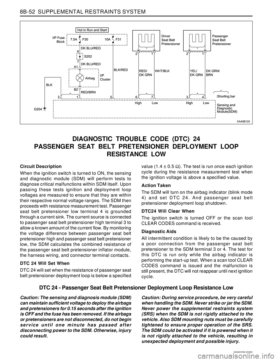
Circuit Description
When the ignition switch is turned to ON, the sensing
and diagnostic module (SDM) will perform tests to
diagnose critical malfunctions within SDM itself. Upon
passing these tests ignition and deployment loop
voltages are measured to ensure that they are within
their respective normal voltage ranges. The SDM then
proceeds with resistance measurement test. Passenger
seat belt pretensioner low terminal 4 is grounded
through a current sink. The current source is connected
to passenger seat belt pretensioner high terminal 3 to
allow a known amount of the current flow. By monitoring
the voltage difference between passenger seat belt
pretensioner high and passenger seat belt pretensioner
low, the SDM calculates the combined resistance of
the passenger seat belt pretensioner inflator module,
the harness wiring, and connector terminal contacts.
DTC 24 Will Set When
DTC 24 will set when the resistance of passenger seat
belt pretensioner deployment loop is below a specified
DIAGNOSTIC TROUBLE CODE (DTC) 24
PASSENGER SEAT BELT PRETENSIONER DEPLOYMENT LOOP
RESISTANCE LOW
value (1.4 ± 0.5 Ω). The test is run once each ignition
cycle during the resistance measurement test when
the ignition voltage is above a specified value.
Action Taken
The SDM will turn on the airbag indicator (blink mode
4) and set DTC 24. And passenger seat belt
pretensioner deployment loop shutdown.
DTC24 Will Clear When
The ignition switch is turned OFF or the scan tool
CLEAR CODES command is received.
Diagnostic Aids
All intermittent condition is likely to be the caused by
a poor connection from the passenger seat belt
pretensioner to the SDM terminal 3 or 4. The test for
this DTC is run only while the airbag indicator is
performing the start-up test. When a scan tool CLEAR
CODES command is issued and the malfunction is
still present, the DTC will not reappear until next ignition
cycle.
KAA8B120
DTC 24 - Passenger Seat Belt Pretensioner Deployment Loop Resistance Low
Caution: The sensing and diagnosis module (SDM)
can maintain sufficient voltage to deploy the airbags
and pretensioners for 0.15 seconds after the ignition
is OFF and the fuse has been removed. If the airbags
or pretensioners are not disconnected, do not begin
service until one minute has passed after
disconnecting power to the SDM. Otherwise, injury
could result.Caution: During service procedure, be very careful
when handling the SDM. Never strike or jar the SDM.
Never power the supplemental restraints system
(SRS) when the SDM is not rigidly attached to the
vehicle. Also SDM mounting nuts must be carefully
tightened to ensure proper operation of the SRS.
The SDM could be activated if it is powered when it
is not rigidly attached to the vehicle, resulting in
unexpected deployment and possible injury.
Page 1637 of 2053
SUPPLEMENTAL RESTRAINTS SYSTEM 8B-55
SSANGYONG MY2002
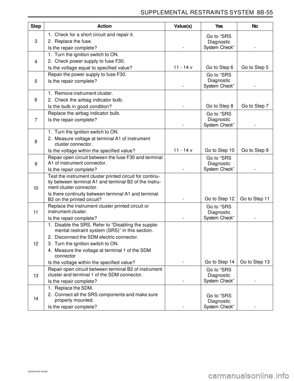
1. Check for a short circuit and repair it.
2. Replace the fuse.
Is the repair complete?
1. Turn the ignition switch to ON.
2. Check power supply to fuse F30.
Is the voltage equal to specified value?
Repair the power supply to fuse F30.
Is the repair complete?
1. Remove instrument cluster.
2. Check the airbag indicator bulb.
Is the bulb in good condition?
Replace the airbag indicator bulb.
Is the repair complete?
1. Turn the ignition switch to ON.
2. Measure voltage at terminal A1 of instrument
cluster connector.
Is the voltage within the specified value?
Repair open circuit between the fuse F30 and terminal
A1 of instrument connector.
Is the repair complete?
Test the instrument cluster printed circuit for continu-
ity between terminal A1 and terminal B2 of the instru-
ment cluster connector.
Is there continuity between terminal A1 and terminal
B2 on the printed circuit?
Replace the instrument cluster printed circuit or
instrument cluster.
Is the repair complete?
1. Disable the SRS. Refer to “Disabling the supple-
mental restraint system (SRS)” in this section.
2. Disconnect the SDM electric connector.
3. Turn the ignition switch to ON.
4. Measure the voltage at terminal 1 of the SDM
connector
Is the voltage within the specified value?
Repair open circuit between terminal B2 of instrument
cluster and terminal 1 of the SDM connector.
Is the repair complete?
1. Replace the SDM.
2. Connect all the SRS components and make sure
properly mounted.
Is the repair complete?
StepAction Value(s) Yes No
4
6
7
8
11 - 14 v Go to Step 6 Go to Step 5
5
-Go to “SRS
Diagnostic
System Check” -
- Go to Step 8 Go to Step 7
-Go to “SRS
Diagnostic
System Check” -
9
10
11
12
-Go to “SRS
Diagnostic
System Check” - 3
11 - 14 v Go to Step 10 Go to Step 9
-Go to “SRS
Diagnostic
System Check” -
13
- Go to Step 12 Go to Step 11
- Go to Step 14 Go to Step 13
-Go to “SRS
Diagnostic
System Check” -
-Go to “SRS
Diagnostic
System Check” - 14
-Go to “SRS
Diagnostic
System Check” -
Page 1652 of 2053
SECTION 9A
BODY WIRING SYSTEM
CAUTION: Disconnect the negative battery cable before removing or installing any electrical unit or when a
tool or equipment could easily come in contact with exposed electrical terminals. Disconnecting this cable
will help prevent personal injury and damage to the vehicle. The ignition must also be in LOCK unless
otherwise noted.
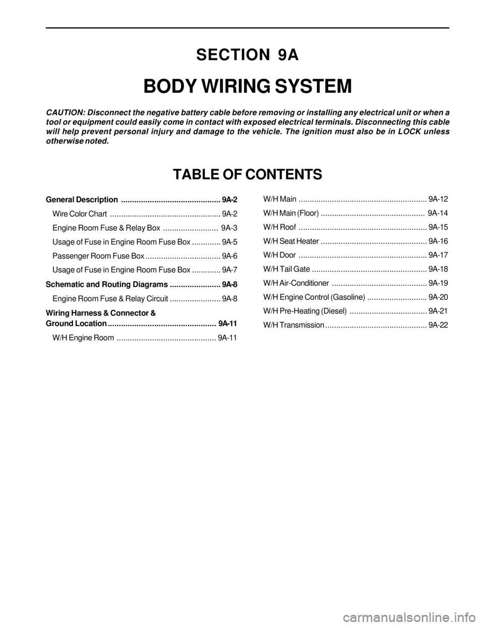
TABLE OF CONTENTS
General Description.............................................9A-2
Wire Color Chart..................................................9A-2
Engine Room Fuse & Relay Box......................... 9A-3
Usage of Fuse in Engine Room Fuse Box.............9A-5
Passenger Room Fuse Box..................................9A-6
Usage of Fuse in Engine Room Fuse Box.............9A-7
Schematic and Routing Diagrams.......................9A-8
Engine Room Fuse & Relay Circuit.......................9A-8
Wiring Harness & Connector &
Ground Location................................................. 9A-11
W/H Engine Room.............................................9A-11W/H Main..........................................................9A-12
W/H Main (Floor)............................................... 9A-14
W/H Roof..........................................................9A-15
W/H Seat Heater................................................9A-16
W/H Door..........................................................9A-17
W/H Tail Gate....................................................9A-18
W/H Air-Conditioner...........................................9A-19
W/H Engine Control (Gasoline)...........................9A-20
W/H Pre-Heating (Diesel)...................................9A-21
W/H Transmission..............................................9A-22
Page 1670 of 2053
BODY WIRING SYSTEM 9A-19
SSANGYONG MY2002
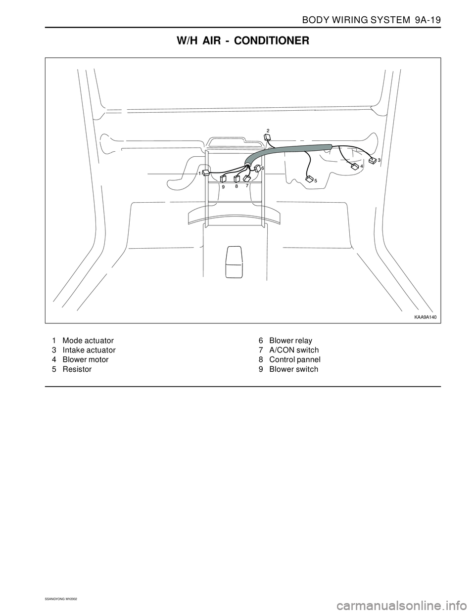
W/H AIR - CONDITIONER
1 Mode actuator
3 Intake actuator
4 Blower motor
5 Resistor6 Blower relay
7 A/CON switch
8 Control pannel
9 Blower switch
KAA9A140
Page 1676 of 2053
SSANGYONG MY2002
9B-2 LIGHTING SYSTEM
DESCRIPTION AND OPERATION
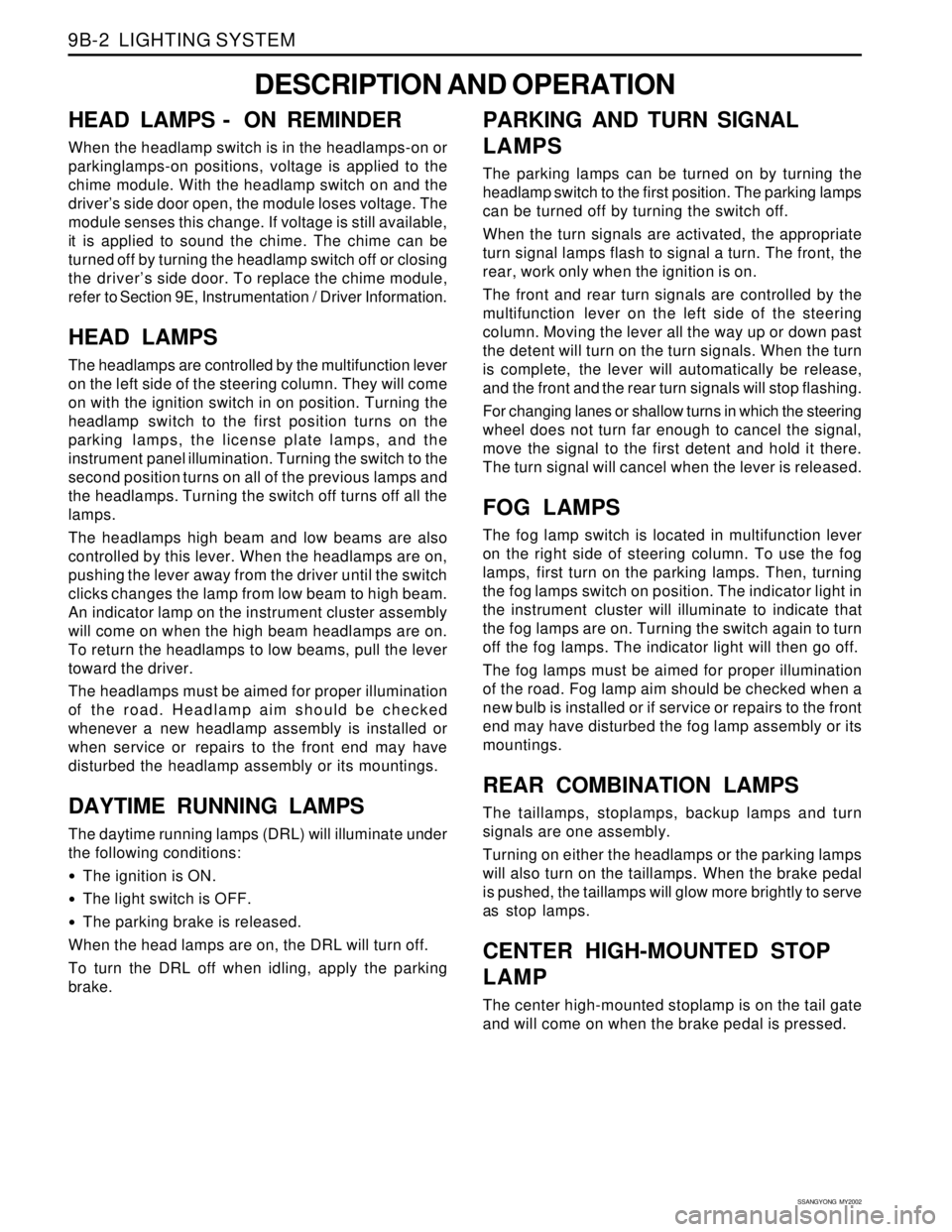
HEAD LAMPS - ON REMINDER
When the headlamp switch is in the headlamps-on or
parkinglamps-on positions, voltage is applied to the
chime module. With the headlamp switch on and the
driver’s side door open, the module loses voltage. The
module senses this change. If voltage is still available,
it is applied to sound the chime. The chime can be
turned off by turning the headlamp switch off or closing
the driver’s side door. To replace the chime module,
refer to Section 9E, Instrumentation / Driver Information.
HEAD LAMPS
The headlamps are controlled by the multifunction lever
on the left side of the steering column. They will come
on with the ignition switch in on position. Turning the
headlamp switch to the first position turns on the
parking lamps, the license plate lamps, and the
instrument panel illumination. Turning the switch to the
second position turns on all of the previous lamps and
the headlamps. Turning the switch off turns off all the
lamps.
The headlamps high beam and low beams are also
controlled by this lever. When the headlamps are on,
pushing the lever away from the driver until the switch
clicks changes the lamp from low beam to high beam.
An indicator lamp on the instrument cluster assembly
will come on when the high beam headlamps are on.
To return the headlamps to low beams, pull the lever
toward the driver.
The headlamps must be aimed for proper illumination
of the road. Headlamp aim should be checked
whenever a new headlamp assembly is installed or
when service or repairs to the front end may have
disturbed the headlamp assembly or its mountings.
DAYTIME RUNNING LAMPS
The daytime running lamps (DRL) will illuminate under
the following conditions:
The ignition is ON.
The light switch is OFF.
The parking brake is released.
When the head lamps are on, the DRL will turn off.
To turn the DRL off when idling, apply the parking
brake.
PARKING AND TURN SIGNAL
LAMPS
The parking lamps can be turned on by turning the
headlamp switch to the first position. The parking lamps
can be turned off by turning the switch off.
When the turn signals are activated, the appropriate
turn signal lamps flash to signal a turn. The front, the
rear, work only when the ignition is on.
The front and rear turn signals are controlled by the
multifunction lever on the left side of the steering
column. Moving the lever all the way up or down past
the detent will turn on the turn signals. When the turn
is complete, the lever will automatically be release,
and the front and the rear turn signals will stop flashing.
For changing lanes or shallow turns in which the steering
wheel does not turn far enough to cancel the signal,
move the signal to the first detent and hold it there.
The turn signal will cancel when the lever is released.
FOG LAMPS
The fog lamp switch is located in multifunction lever
on the right side of steering column. To use the fog
lamps, first turn on the parking lamps. Then, turning
the fog lamps switch on position. The indicator light in
the instrument cluster will illuminate to indicate that
the fog lamps are on. Turning the switch again to turn
off the fog lamps. The indicator light will then go off.
The fog lamps must be aimed for proper illumination
of the road. Fog lamp aim should be checked when a
new bulb is installed or if service or repairs to the front
end may have disturbed the fog lamp assembly or its
mountings.
REAR COMBINATION LAMPS
The taillamps, stoplamps, backup lamps and turn
signals are one assembly.
Turning on either the headlamps or the parking lamps
will also turn on the taillamps. When the brake pedal
is pushed, the taillamps will glow more brightly to serve
as stop lamps.
CENTER HIGH-MOUNTED STOP
LAMP
The center high-mounted stoplamp is on the tail gate
and will come on when the brake pedal is pressed.