1997 SSANGYONG KORANDO air condition
[x] Cancel search: air conditionPage 1571 of 2053
FATC-HAVC 7D-17
SSANGYONG MY2002
KAA7D150
KAA7D160
KAA7D170
KAA7D180
TROUBLESHOOTING
Check and Service
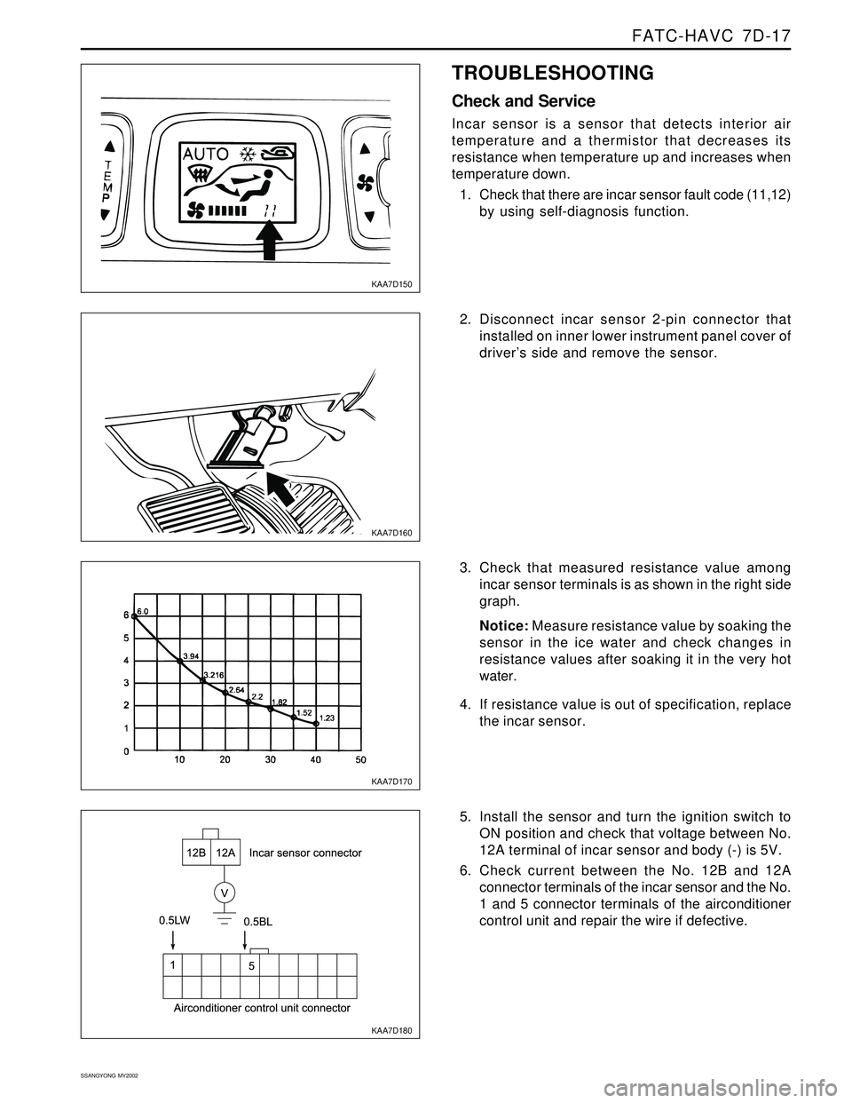
Incar sensor is a sensor that detects interior air
temperature and a thermistor that decreases its
resistance when temperature up and increases when
temperature down.
1. Check that there are incar sensor fault code (11,12)
by using self-diagnosis function.
2. Disconnect incar sensor 2-pin connector that
installed on inner lower instrument panel cover of
driver’s side and remove the sensor.
3. Check that measured resistance value among
incar sensor terminals is as shown in the right side
graph.
Notice: Measure resistance value by soaking the
sensor in the ice water and check changes in
resistance values after soaking it in the very hot
water.
4. If resistance value is out of specification, replace
the incar sensor.
5. Install the sensor and turn the ignition switch to
ON position and check that voltage between No.
12A terminal of incar sensor and body (-) is 5V.
6. Check current between the No. 12B and 12A
connector terminals of the incar sensor and the No.
1 and 5 connector terminals of the airconditioner
control unit and repair the wire if defective.
Page 1572 of 2053
SSANGYONG MY2002
7D-18 FATC-HAVC
KAA7D190
KAA7D200
KAA7D210
KAA7D220
Ambient Sensor
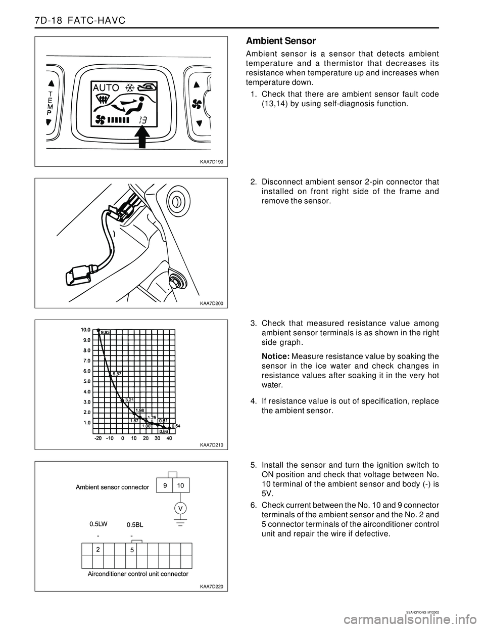
Ambient sensor is a sensor that detects ambient
temperature and a thermistor that decreases its
resistance when temperature up and increases when
temperature down.
1. Check that there are ambient sensor fault code
(13,14) by using self-diagnosis function.
2. Disconnect ambient sensor 2-pin connector that
installed on front right side of the frame and
remove the sensor.
3. Check that measured resistance value among
ambient sensor terminals is as shown in the right
side graph.
Notice: Measure resistance value by soaking the
sensor in the ice water and check changes in
resistance values after soaking it in the very hot
water.
4. If resistance value is out of specification, replace
the ambient sensor.
5. Install the sensor and turn the ignition switch to
ON position and check that voltage between No.
10 terminal of the ambient sensor and body (-) is
5V.
6. Check current between the No. 10 and 9 connector
terminals of the ambient sensor and the No. 2 and
5 connector terminals of the airconditioner control
unit and repair the wire if defective.
Page 1573 of 2053
FATC-HAVC 7D-19
SSANGYONG MY2002
KAA7D230
KAA7D240
KAA7D250
KAA7D260
Water Sensor
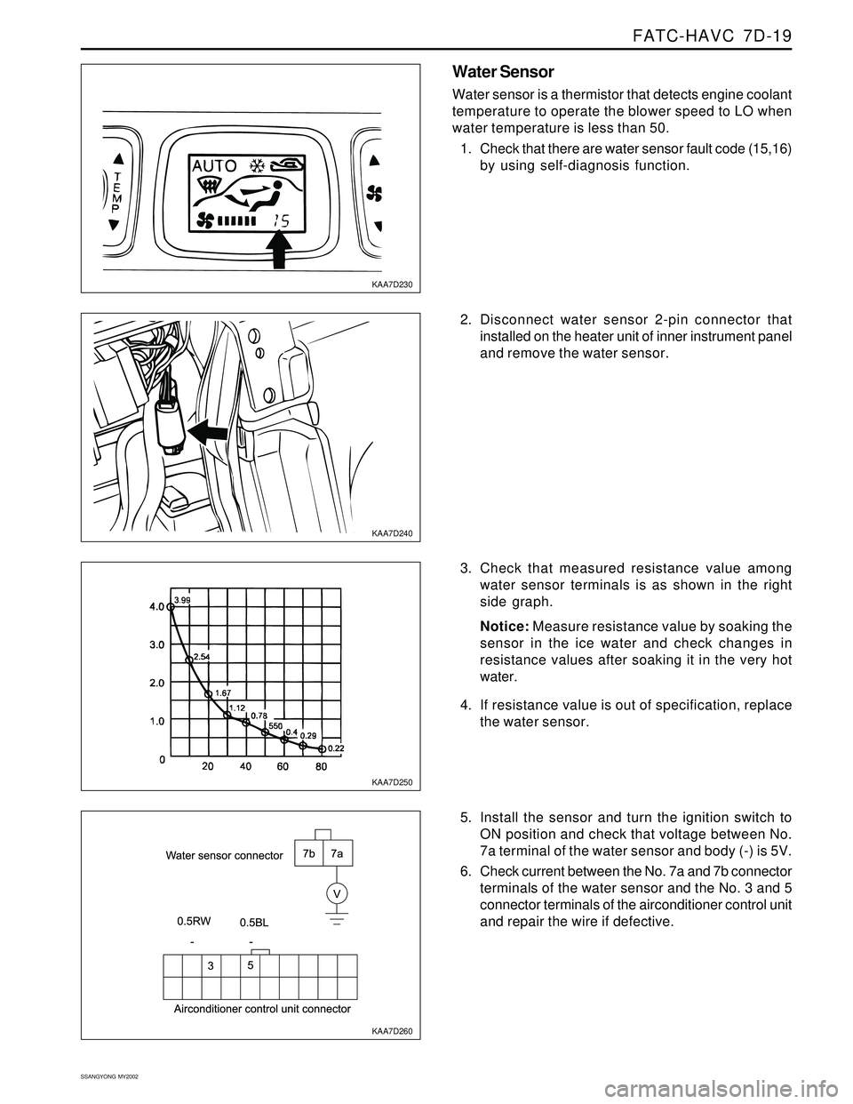
Water sensor is a thermistor that detects engine coolant
temperature to operate the blower speed to LO when
water temperature is less than 50.
1. Check that there are water sensor fault code (15,16)
by using self-diagnosis function.
2. Disconnect water sensor 2-pin connector that
installed on the heater unit of inner instrument panel
and remove the water sensor.
3. Check that measured resistance value among
water sensor terminals is as shown in the right
side graph.
Notice: Measure resistance value by soaking the
sensor in the ice water and check changes in
resistance values after soaking it in the very hot
water.
4. If resistance value is out of specification, replace
the water sensor.
5. Install the sensor and turn the ignition switch to
ON position and check that voltage between No.
7a terminal of the water sensor and body (-) is 5V.
6. Check current between the No. 7a and 7b connector
terminals of the water sensor and the No. 3 and 5
connector terminals of the airconditioner control unit
and repair the wire if defective.
Page 1574 of 2053
SSANGYONG MY2002
7D-20 FATC-HAVC
KAA7D270
KAA7D280
KAA7D290
KAA7D300
Sun load Sensor
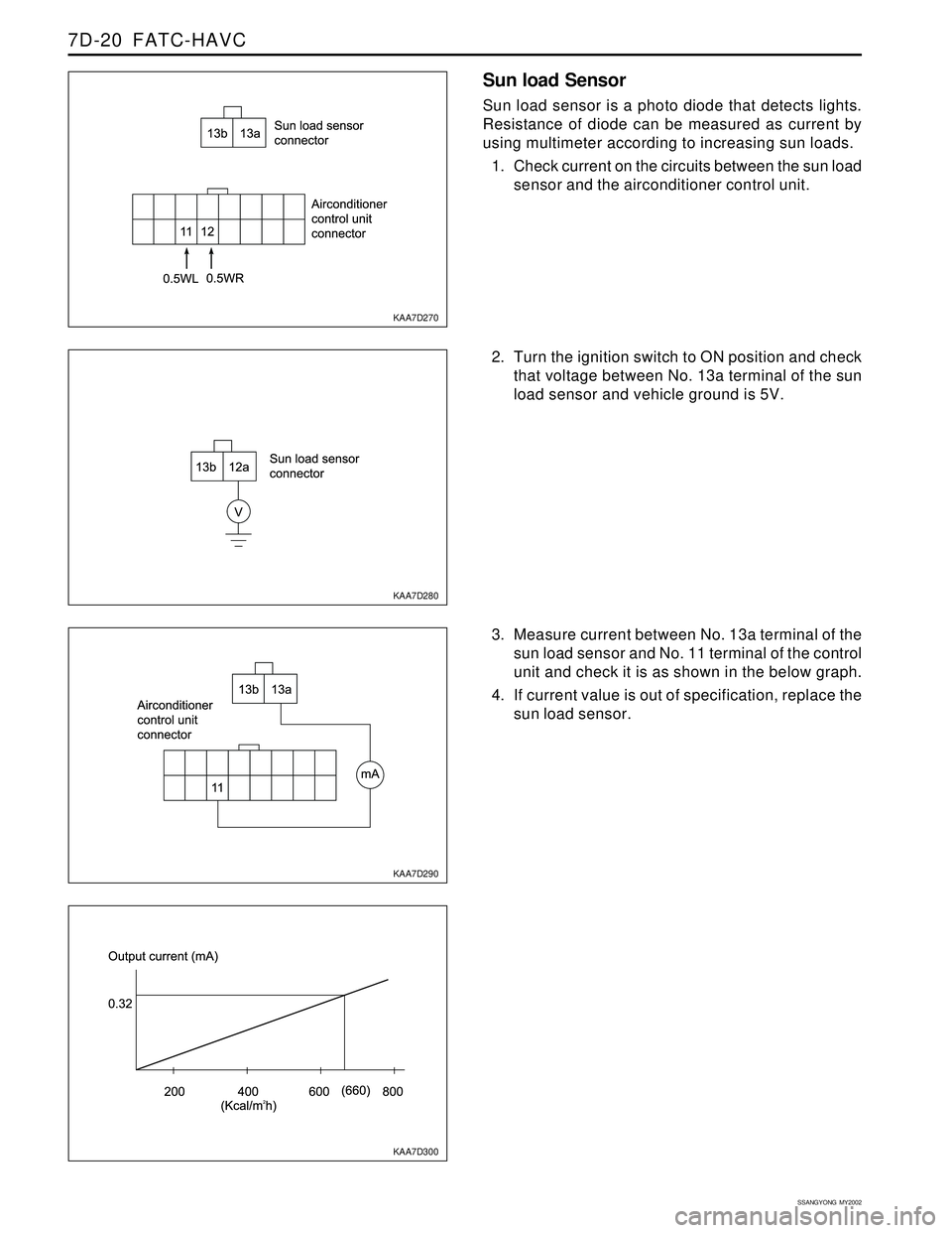
Sun load sensor is a photo diode that detects lights.
Resistance of diode can be measured as current by
using multimeter according to increasing sun loads.
1. Check current on the circuits between the sun load
sensor and the airconditioner control unit.
2. Turn the ignition switch to ON position and check
that voltage between No. 13a terminal of the sun
load sensor and vehicle ground is 5V.
3. Measure current between No. 13a terminal of the
sun load sensor and No. 11 terminal of the control
unit and check it is as shown in the below graph.
4. If current value is out of specification, replace the
sun load sensor.
Page 1575 of 2053
FATC-HAVC 7D-21
SSANGYONG MY2002
KAA7D310
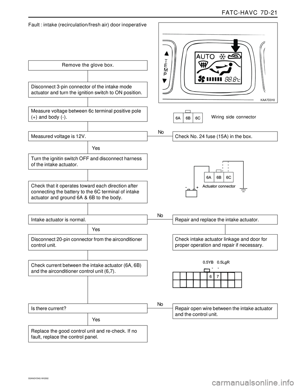
Fault : intake (recirculation/fresh air) door inoperative
Remove the glove box.
Check No. 24 fuse (15A) in the box.
YesNo
Check that it operates toward each direction after
connecting the battery to the 6C terminal of intake
actuator and ground 6A & 6B to the body.
Wiring side connector
Intake actuator is normal.
YesRepair and replace the intake actuator. No
Check intake actuator linkage and door for
proper operation and repair if necessary.Disconnect 20-pin connector from the airconditioner
control unit.
Check current between the intake actuator (6A, 6B)
and the airconditioner control unit (6,7).
Is there current?
YesRepair open wire between the intake actuator
and the control unit. No
Replace the good control unit and re-check. If no
fault, replace the control panel.
Measure voltage between 6c terminal positive pole
(+) and body (-).
Measured voltage is 12V.
Turn the ignitin switch OFF and disconnect harness
of the intake actuator.
Disconnect 3-pin connector of the intake mode
actuator and turn the ignition switch to ON position.
Page 1576 of 2053
SSANGYONG MY2002
7D-22 FATC-HAVC
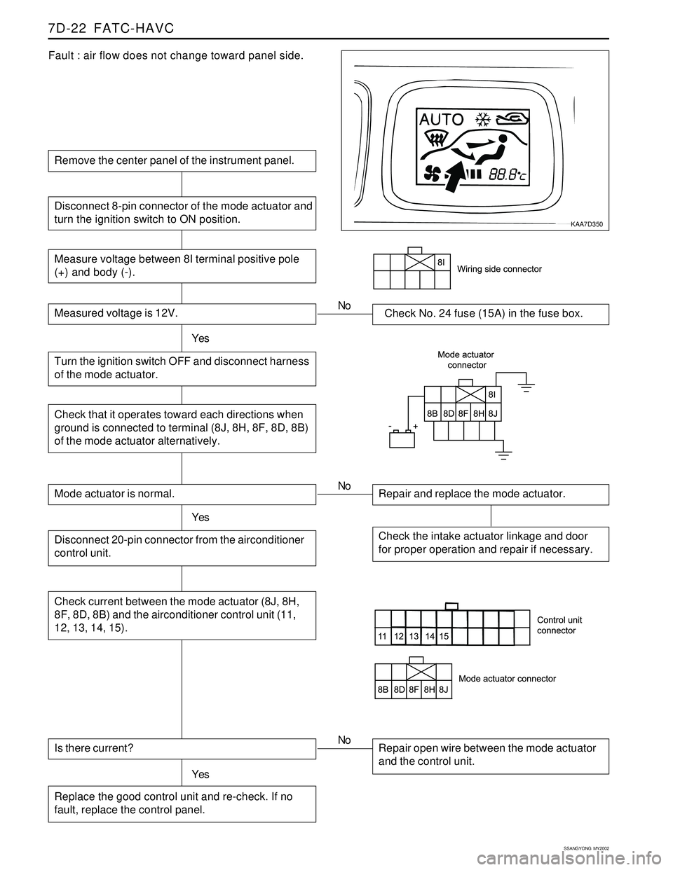
Fault : air flow does not change toward panel side.
Remove the center panel of the instrument panel.
Measure voltage between 8I terminal positive pole
(+) and body (-).
Measured voltage is 12V.Check No. 24 fuse (15A) in the fuse box.
Turn the ignition switch OFF and disconnect harness
of the mode actuator.YesNo
Disconnect 8-pin connector of the mode actuator and
turn the ignition switch to ON position.
Check that it operates toward each directions when
ground is connected to terminal (8J, 8H, 8F, 8D, 8B)
of the mode actuator alternatively.
Mode actuator is normal.
YesRepair and replace the mode actuator. No
Check the intake actuator linkage and door
for proper operation and repair if necessary.Disconnect 20-pin connector from the airconditioner
control unit.
Check current between the mode actuator (8J, 8H,
8F, 8D, 8B) and the airconditioner control unit (11,
12, 13, 14, 15).
Is there current?
YesRepair open wire between the mode actuator
and the control unit. No
Replace the good control unit and re-check. If no
fault, replace the control panel.
KAA7D350
Page 1578 of 2053
SSANGYONG MY2002
8A-2 SEAT BELTS
DESCRIPTION AND OPERATION
DRIVER SEAT BELT WARNING
The driver’s seat belt incorporates a seat belt warning
lamp in the instrument cluster to remind the driver if
the seat belt is not fastened when the ignition is turned
ON. The warning lamp blinks for eight seconds with
chime and goes out.
THREE-POINT FRONT SEAT BELT
WITH PRETENSIONER
The front seat belt contains an electronically controlled
pyrotechnic retractor, pretensioner, which reduces seat
belt slack when it activated in a head-on or angled
front collision. The front seat belt must be replaced
after an accident that causes its activation. At normal
condition the driver’s seat belt operates as emergency
locking retractor (ELR).
Emergency Locking Retractor (ELR)
The ELR seat belt is always unlocked, allowing the
passenger freedom of movement, except in
emergencies such as rapid deceleration, rapid
acceleration, or hard cornering maneuvers.
THREE-POINT REAR OUTBOARD
SEAT BELT
The rear outboard seating position uses the emergency
locking retractor (ELR). Refer to Three-point front seat
belt with pretensioner in this section for details.
TWO-POINT LAP REAR CENTER
SEAT BELT
The two-point lap rear center seat belt is a single contin-
uous length of webbing. The webbing is routed from
the anchor through plate and into a single retractor.
OPERATIONAL AND FUNCTIONAL
CHECKS
Caution:
Keep sharp objects and potentially damaged ob
jects away from seat belts.
Avoid bending or damaging any portion of
buckle or the latch plate
Do not breach or dye the belt webbing. Use only
mild soap and water in order to clean the belts.
When installing the seat belt anchor bolts and
screws, start the bolts and screws by hand in or-
der to prevent cross-threading.
Do not attempt any repairs on the retractor mech-
anisms or covers. Replace any defective assem-
blies with new assemblies.
Replace any belts that are cut or damaged in any
way.
1. Inspect all seat anchor bolts and screws in order to
verify that they are secure.
2. Inspect the seat belt buckle. The buckle must lock
and unlock easily.
3. After inserting the latch into the buckle, tug sharply
on the belt. The buckle must remain locked.
4. Fully extend the shoulder belt portion to make sure
that there is no twisting or tears in the belt.
5. Let the shoulder belt retract fully. The belt should
retract easily.
CHILD SEAT TETHER ANCHOR
There are three child seat tether anchors to hold the
child seat firmly. One is located rear center of ceiling
and two are located on the rear corner of floor.
Page 1588 of 2053
SUPPLEMENTAL RESTRAINTS SYSTEM 8B-3
SSANGYONG MY2002
SUPPLEMENTAL RESTRAINT
SYSTEM (SRS)
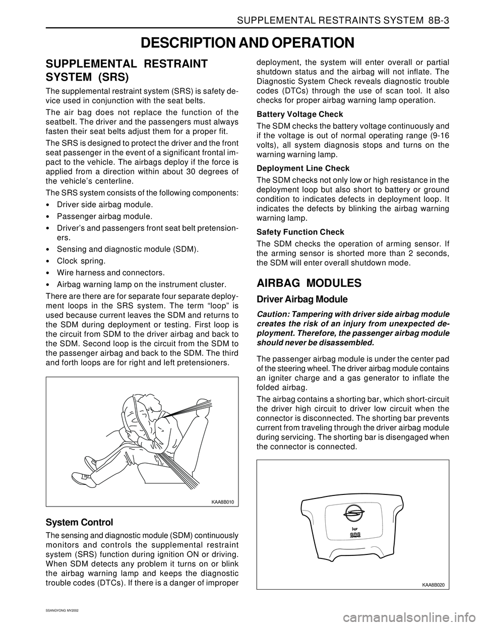
The supplemental restraint system (SRS) is safety de-
vice used in conjunction with the seat belts.
The air bag does not replace the function of the
seatbelt. The driver and the passengers must always
fasten their seat belts adjust them for a proper fit.
The SRS is designed to protect the driver and the front
seat passenger in the event of a significant frontal im-
pact to the vehicle. The airbags deploy if the force is
applied from a direction within about 30 degrees of
the vehicle’s centerline.
The SRS system consists of the following components:
Driver side airbag module.
Passenger airbag module.
Driver’s and passengers front seat belt pretension-
ers.
Sensing and diagnostic module (SDM).
Clock spring.
Wire harness and connectors.
Airbag warning lamp on the instrument cluster.
There are there are for separate four separate deploy-
ment loops in the SRS system. The term “loop” is
used because current leaves the SDM and returns to
the SDM during deployment or testing. First loop is
the circuit from SDM to the driver airbag and back to
the SDM. Second loop is the circuit from the SDM to
the passenger airbag and back to the SDM. The third
and forth loops are for right and left pretensioners.
DESCRIPTION AND OPERATION
KAA8B010
deployment, the system will enter overall or partial
shutdown status and the airbag will not inflate. The
Diagnostic System Check reveals diagnostic trouble
codes (DTCs) through the use of scan tool. It also
checks for proper airbag warning lamp operation.
Battery Voltage Check
The SDM checks the battery voltage continuously and
if the voltage is out of normal operating range (9-16
volts), all system diagnosis stops and turns on the
warning warning lamp.
Deployment Line Check
The SDM checks not only low or high resistance in the
deployment loop but also short to battery or ground
condition to indicates defects in deployment loop. It
indicates the defects by blinking the airbag warning
warning lamp.
Safety Function Check
The SDM checks the operation of arming sensor. If
the arming sensor is shorted more than 2 seconds,
the SDM will enter overall shutdown mode.
AIRBAG MODULES
Driver Airbag Module
Caution: Tampering with driver side airbag module
creates the risk of an injury from unexpected de-
ployment. Therefore, the passenger airbag module
should never be disassembled.
The passenger airbag module is under the center pad
of the steering wheel. The driver airbag module contains
an igniter charge and a gas generator to inflate the
folded airbag.
The airbag contains a shorting bar, which short-circuit
the driver high circuit to driver low circuit when the
connector is disconnected. The shorting bar prevents
current from traveling through the driver airbag module
during servicing. The shorting bar is disengaged when
the connector is connected.
System Control
The sensing and diagnostic module (SDM) continuously
monitors and controls the supplemental restraint
system (SRS) function during ignition ON or driving.
When SDM detects any problem it turns on or blink
the airbag warning lamp and keeps the diagnostic
trouble codes (DTCs). If there is a danger of improper
KAA8B020