Page 1254 of 2053
5A-156 AUTOMATIC TRANSMISSION
SSANGYONG MY2002
DTC P1747 Solenoid 7 Circuit Short (Cont’d)
Check for a poor connection at the 10-way transmission
connector and TCM connector and repair the malfunc-
tioning terminals as necessary.
Is a repair necessary?
1. Turn the ignition OFF.
2. Replace the TCM.
Is the action complete?
1. Using the scan tool, clear the DTCs.
2. Road test the vehicle within the conditions for
setting this DTC as specified in the text.
Does the scan tool indicate that this diagnostic has
run and passed?
Check if any DTCs are set.
Are there any DTCs displayed or previously recorded
at Step 2 that have not been diagnosed?
StepAction Value(s) Yes No
10
- Go to Step 12 Go to Step 11
13 11
- Go to Step 12 -
12
- Go to Step 13 Go to Step 2
-Go to
applicable
DTC tableSystem OK,
Check
Complete
Page 1384 of 2053
SSANGYONG MY2002
5D1-14 TRANSFER CASE
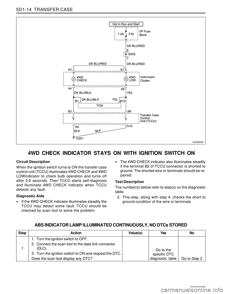
4WD CHECK INDICATOR STAYS ON WITH IGNITION SWITCH ON
KAA5D040
Circuit Description
When the ignition switch turns to ON the transfer case
control unit (TCCU) illuminates 4WD CHECK and 4WD
LOWindicator to check bulb operation and turns off
after 0.6 seconds. Then TCCU starts self-diagnosis
and illuminate 4WD CHECK indicator when TCCU
detects any fault.
Diagnostic Aids
If the 4WD CHECK indicator illuminates steadily the
TCCU may detect some fault. TCCU should be
checked by scan tool to solve the problem.
The 4WD CHECK indicator also illuminates steadily
if the terminal B2 of TCCU connector is shorted to
ground. The shorted wire or terminals should be re-
paired.
Test Description
The number(s) below refer to step(s) on the diagnostic
table.
2. This step, along with step 4, checks the short to
ground condition of the wire or terminals
Step
1
ABS INDICATOR LAMP ILLUMINATED CONTINUOUSLY, NO DTCs STORED
Action Yes
Go to the
specific DTC
diagnostic tableNo
Go to Step 2 Value(s)
1. Turn the ignition switch to OFF.
2. Connect the scan tool to the data link connector
(DLC).
3. Turn the ignition switch to ON and request the DTC.
Does the scan tool display any DTC?
Page 1386 of 2053
SSANGYONG MY2002
5D1-16 TRANSFER CASE
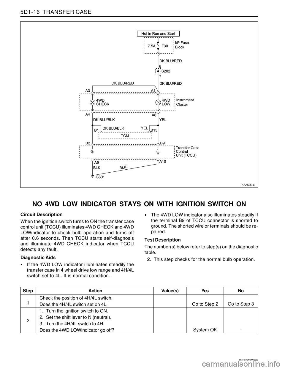
KAA5D040
NO 4WD LOW INDICATOR STAYS ON WITH IGNITION SWITCH ON
Circuit Description
When the ignition switch turns to ON the transfer case
control unit (TCCU) illuminates 4WD CHECK and 4WD
LOWindicator to check bulb operation and turns off
after 0.6 seconds. Then TCCU starts self-diagnosis
and illuminate 4WD CHECK indicator when TCCU
detects any fault.
Diagnostic Aids
If the 4WD LOW indicator illuminates steadily the
transfer case in 4 wheel drive low range and 4H/4L
switch set to 4L. It is normal condition.
The 4WD LOW indicator also illuminates steadily if
the terminal B9 of TCCU connector is shorted to
ground. The shorted wire or terminals should be re-
paired.
Test Description
The number(s) below refer to step(s) on the diagnostic
table.
2. This step checks for the normal bulb operation.
Step
1
2
Action Yes
Go to Step 2
System OKNo
Go to Step 3
- Value(s)
Check the position of 4H/4L switch.
Does the 4H/4L switch set on 4L.
1. Turn the ignition switch to ON.
2. Set the shift lever to N (neutral).
3. Turn the 4H/4L switch to 4H.
Does the 4WD LOWindicator go off?
Page 1411 of 2053
TRANSFER CASE (PART TIME - 4408) 5D2-11
SSANGYONG MY2002
KAA5D080
KAA5D090
KAA5D100
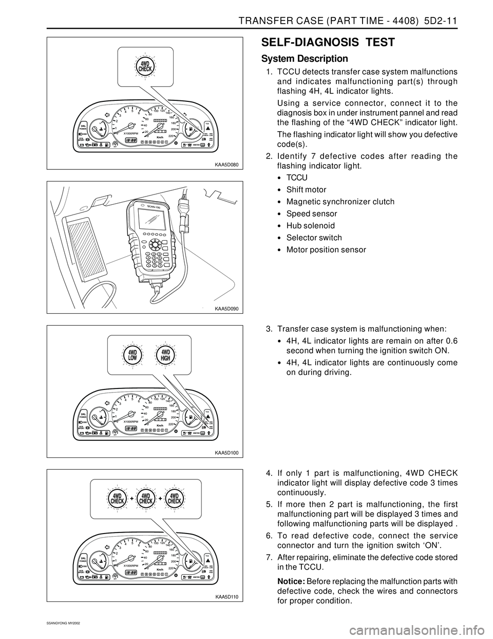
SELF-DIAGNOSIS TEST
System Description
1. TCCU detects transfer case system malfunctions
and indicates malfunctioning part(s) through
flashing 4H, 4L indicator lights.
Using a service connector, connect it to the
diagnosis box in under instrument pannel and read
the flashing of the “4WD CHECK” indicator light.
The flashing indicator light will show you defective
code(s).
2. Identify 7 defective codes after reading the
flashing indicator light.
TCCU
Shift motor
Magnetic synchronizer clutch
Speed sensor
Hub solenoid
Selector switch
Motor position sensor
KAA5D110
3. Transfer case system is malfunctioning when:
4H, 4L indicator lights are remain on after 0.6
second when turning the ignition switch ON.
4H, 4L indicator lights are continuously come
on during driving.
4. If only 1 part is malfunctioning, 4WD CHECK
indicator light will display defective code 3 times
continuously.
5. If more then 2 part is malfunctioning, the first
malfunctioning part will be displayed 3 times and
following malfunctioning parts will be displayed .
6. To read defective code, connect the service
connector and turn the ignition switch ‘ON’.
7. After repairing, eliminate the defective code stored
in the TCCU.
Notice: Before replacing the malfunction parts with
defective code, check the wires and connectors
for proper condition.
Page 1429 of 2053
TRANSFER CASE (PART TIME - 4408) 5D2-31
SSANGYONG MY2002
Cleaning Procedure
Notice: Before cleaning, check the magnet for the
presence of metal particles which indicate internal
chipping of the transfer case.
1. Using cleaning solvent, clean the residual oil and
dirt deposits.
Notice: During cleaning, be careful not to damage
the metal surfaces.
2. After cleaning, dry the parts with low pressure(Max.
20 psi) compressed air.
3. Lubricate the ball bearings and needle bearings
with transfer case oil after cleaning.
Notice: Protect the lubricated bearings from dust.
Inspection Procedure
1. Visually check the all removed parts.
Notice: Always replace the hose coupling, O-ring
and oil seal with new parts.
2. Inspection Terms
Burr : Local rise of material forming protruding
sharp edge
Chip : An area from which a small fragment has
been broken off or cut
Crack : Surface break of line nature indicating
partial or complete separation of material.
Excessive wear : Heavy or obvious wear beyond
expectations considering conditions of
operation.
Indentation : Displacement of material caused
by localized heavy contact.
Galling : Breakdown of metal surface due to
excessive friction between parts. Particles of
the softer material are torn loose and welded to
the harder material.
Nick : Local break or notch, usually displacement
of material rather than loss.
Scoring : Tear or break in metal surface from
contact under abnormal pressure.
Page 1430 of 2053
SSANGYONG MY2002
5D2-32 TRANSFER CASE (PART TIME - 4408)
Step wear : Heavy wear that produces a step
that can be seen or felt between adjacent
contact and non-contact surfaces.
Uneven wear : Condition of localized, unevenly
distributed wear Includes hollows, shiny spots,
uneven polish and other visual indications.
3. Specific Inspection
Referring to normal gear tooth face, specifically
inspect the uneven wear and chips of gear tooth.
Replace or repair if necessary.
KAA5D590
Page 1463 of 2053
SSANGYONG MY2002
6B-2 POWER STEERING PUMP
DESCRIPTION AND OPERATION
GENERAL DESCRIPTION
The power steering pump is a multivaned hydraulic
pump. The serpentine accessory drive belt on the en-
gine drives the power steering pump. The power steer-
ing pump provides the hydraulic pressure to the power
steering gear.
The power steering gear uses the hydraulic pressure
to assist in steering the vehicle.
When steering conditions exceed maximum pressure
requirements, such as when the wheels are turned
against the stops, the pressure built up in the steeringgear exerts pressure on the spring end of the flow
control valve. The high pressure lifts the relief valve
ball from its seat and allows oil to flow through a trigger
orifice located in the outlet fitting. This reduce pressure
on the spring end of the flow control valve which then
opens and allows the oil to return to the intake side of
the pump. This action limits maximum pressure output
of the pump to a safe level.
No repair procedures are to be done on the internal
components of the power steering pump. The only ser-
viceable components of the power steering pump are
the power steering pump pulley and the pump itself.
Page 1498 of 2053
SSANGYONG MY2002
6E-12 POWER STEERING AND COLUMN
KAA6E040
KAA6E120
STEERING COLUMN
Important: Remove the steering column only if the
following conditions exist:
The steering column requires replacement.
The steering and the ignition lock housing require
replacement.
Another operation requires the removal of the
steering column
Notice: The steering column is extremely
susceptible to damage after it has been removed
from the vehicle. Dropping the column assembly
on its end or hammering the end of the steering
shaft can collapse the steering shaft or loosen the
plastic injections which maintain column rigidity.
Leaning on the column can cause it to bend or
deform. Any of the above damage can impair the
column’s collapsible design. If it is necessary to
remove the steering wheel, use only the specified
steering wheel puller.
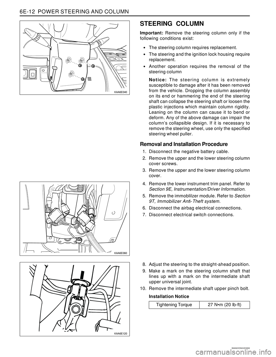
Removal and Installation Procedure
1. Disconnect the negative battery cable.
2. Remove the upper and the lower steering column
cover screws.
3. Remove the upper and the lower steering column
cover.
KAA6E060
4. Remove the lower instrument trim panel. Refer to
Section 9E, Instrumentation/Driver Information.
5. Remove the immoblilzer module. Refer to Section
9T, Immobilizer Anti-Theft system.
6. Disconnect the airbag electrical connections.
7. Disconnect electrical switch connections.
8. Adjust the steering to the straight-ahead position.
9. Make a mark on the steering column shaft that
lines up with a mark on the intermediate shaft
upper universal joint.
10. Remove the intermediate shaft upper pinch bolt.
Installation Notice
Tightening Torque 27 Nm (20 lb-ft)