1997 SSANGYONG KORANDO ecm
[x] Cancel search: ecmPage 508 of 2053

1F2 -- 90 M161 ENGINE CONTROLS
D AEW OO M Y_2000
INTERNAL FAILURE
Failure
CodeDescriptionTrouble AreaMaintenance Hint
21Transmission coding
failureWhen faulty of variant coding
of transmission
DInspection the coding condition
through scan tool
DInspection the Engine Control Module
(ECM)
DInspection the CAN line
DInspection the TCM
136ECM failure (RAM)
When malfunction of random
access memory -- ECM
internal error
DInspection the ECM
142Uncoded/ unprogramed
ECMWhen malfunction of ECM
coding-- required ECM
encoding
DFulfill the ECM variant coding
137ECM failure (EPROM)
143
ECM failure
(EEPROM/Flash -- EPPOM
checksum failure)
144ECM failure (coding ID
checksum failure)When malfunction of ECM
internalDInspection the ECM
145ECM failure (coding
checksum failure)
146ECM failure (programming
checksum failure)
Page 510 of 2053

1F2 -- 92 M161 ENGINE CONTROLS
D AEW OO M Y_2000
ELECTRONIC THROTTLE CONTROLLER SAFETY MALFUNCTION
Failure
CodeDescriptionTrouble AreaMaintenance Hint
110Throttle actuator
learning data fault
110Exceed fuel-- cut safety
time
120
Cruise control
interruption memory
failure
138Call Monitoring
139
Servo motor control
output interruption
memory failure
140Servo motor open/short
186ECM failure
(incompatible CPU)
187ECM failure (CPUs
communication failure)
188ECM failure (CPU 2
configuration failure)
189ECM failure (CPU 2
fault)
190
ECM failure (CPU run
time failure between
CPUs)System internal failureDInspection the Engine Control Module
(ECM)
231
ECM failure (CPU 2
cruise control message
counter failure)
232Over deceleration limit
(CPU 2)
233Over acceleration limit
(CPU 2)
234Cruise control lever dual
operation (CPU 2)
235
Cruise control lever
safety terminal failure
(CPU 2)
236Unusual pedal position
variation (CPU 2)
237Unusual throttle position
variation (CPU 2)
238
Unusual throttle
controller monitoring
data comparison fault
(CPU 2)
Page 511 of 2053

M161 ENGINE CONTROLS 1F2 -- 93
D AEW OO M Y_2000
Failure
CodeDescriptionTrouble AreaMaintenance Hint
239
Unusual accelerator
pedal position sensor
comparison fault
(CPU 2)
240
Throttle potentiometer
comparison fault
(CPU 2)
241Unusual CPU
communication (CPU 2)
242Unusual CPU
configuration (CPU 2)
243A/D converter failure
(CPU 2)
244
Accelerator pedal
position sensor setpoint
fault between CPU 1
and CPU 2
System internal failureDInspection the Engine Control Module
(ECM)
245
Position controller
setpoint fault between
CPU 1 and CPU 2
y(ECM)
246
MSR setpoint fault
between CPU 1 and
CPU 2
247
Idle control setpoint fault
between CPU 1 and
CPU 2
248A/D converter overflow
(CPU 2)
249ROM fault (CPU 2)
250RAM fault (CPU 2)
251Cycle monitor fault
(CPU 2)
Page 512 of 2053

1F2 -- 94 M161 ENGINE CONTROLS
D AEW OO M Y_2000
IMMOBILIZER
KAB1F360
Failure
CodeDescriptionTrouble AreaMaintenance Hint
25Communication with
transponder missingWhen missing the
transponder signal
DInspection the Engine Control Module
(ECM) pin 13, 14 about short circuit or
open with bad contact
DInspection the power source or ground
short circuit or open of immobilizer unit
DInspection the transponder condition
(broken etc.)
DInspection the ECM
141Unprogramed ECM with
immobilizer
When malfunction of
immobilizer
Required immobilizer
encoding, no paired condition
of immobilizer even through
start trial
DFulfill the immobilizer pairing
Circuit Description
Immobilizer is a device disabling vehicle ignition unless a specific key is used and designed to help prevent vehicle
theft.
Immobilizer is comprised of two devices, a key with encoded transponder and ECM with the same encoding of the
transponder. When a key is inserted into the hole to start vehicle and turned to ON, the ECM reads and decodes the
transponder code and, if the same, starts the engine, it is called immobilizer. It means immobilizersystem disables
starting by stopping fuel supply if the code in the transponder does not match the code stored in ECM each other.
Page 523 of 2053

M161 ENGINE CONTROLS 1F2 -- 105
D AEW OO M Y_2000
4. Check the O-ring for damage and replace it if neces-
sary.
5. Installation should follow the removal procedure in
the reverse order.
KAA1F160
CRANKSHAFT POSITION SENSOR
Removal and installation Procedure
1. Disconnect the negative battery cable.
2. Disconnect the electrical connector at the crankshaft
position sensor.
3. Remove the crankshaft position sensor retaining bolt.
Installation Notice
Tightening Torque
10 NSm (89 lb-in)
4. Installation should follow the removal procedure in
the reverse order.
KAA1F200
ENGINE CONTROL MODULE
Removal and installation Procedure
1. Disconnect the negative battery cable.
2. Remove the cowl side trim form passenger side. Re-
fer toSection 9G, Interior trim.
3. Remove the four securing nuts for the Engine Control
Module (ECM) from the mounting bracket.
Installation Notice
Tightening Torque
10 NSm (89 lb-in)
4. Pull out the ECM from the bracket.
5. Disconnect the vehicle side coupling.
6. Installation should follow the removal procedure in
the reverse order.
Page 1099 of 2053

AUTOMATIC TRANSMISSION 5A-5
SSANGYONG MY2002
Engine Speed
The engine speed signal is derived from the Control-
ler Area Network (CAN) via Engine Control Module
(ECM).
Vehicle Speed
The vehicle speed sensor, which is located in the
transfer case, sends the output shaft speed signal
to the Engine Control Module (ECM). The information
is then transferred to the TCM via the CAN.
Transmission Fluid Temperature
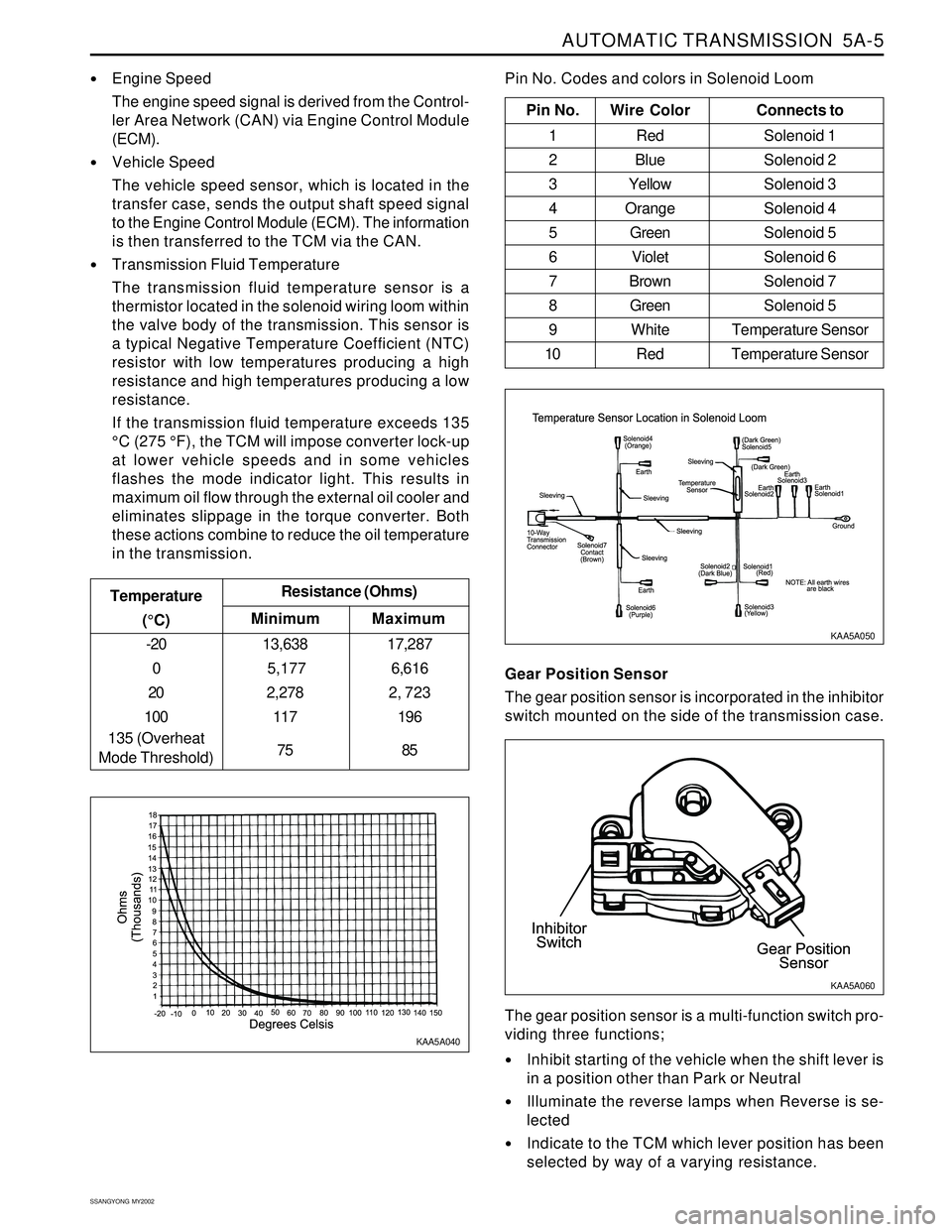
The transmission fluid temperature sensor is a
thermistor located in the solenoid wiring loom within
the valve body of the transmission. This sensor is
a typical Negative Temperature Coefficient (NTC)
resistor with low temperatures producing a high
resistance and high temperatures producing a low
resistance.
If the transmission fluid temperature exceeds 135
°C (275 °F), the TCM will impose converter lock-up
at lower vehicle speeds and in some vehicles
flashes the mode indicator light. This results in
maximum oil flow through the external oil cooler and
eliminates slippage in the torque converter. Both
these actions combine to reduce the oil temperature
in the transmission.
Minimum Temperature
(°C)Resistance (Ohms)
-20
0
20
100
135 (Overheat
Mode Threshold)13,638
5,177
2,278
117
75
Maximum
17,287
6,616
2, 723
196
85
Pin No. Wire ColorConnects to
1 Red Solenoid 1
2 BlueSolenoid 2
3 YellowSolenoid 3
4 OrangeSolenoid 4
5 GreenSolenoid 5
6 VioletSolenoid 6
7 BrownSolenoid 7
8 GreenSolenoid 5
9 White Temperature Sensor
10 Red Temperature Sensor
Pin No. Codes and colors in Solenoid Loom
KAA5A040KAA5A050
Gear Position Sensor
The gear position sensor is incorporated in the inhibitor
switch mounted on the side of the transmission case.
Inhibit starting of the vehicle when the shift lever is
in a position other than Park or Neutral
Illuminate the reverse lamps when Reverse is se-
lected
Indicate to the TCM which lever position has been
selected by way of a varying resistance. The gear position sensor is a multi-function switch pro-
viding three functions;
KAA5A060
Page 1102 of 2053

5A-8 AUTOMATIC TRANSMISSION
SSANGYONG MY2002
Solenoid Valve Symbols
(ON/OFF Solenoids)
The solenoid symbol shown adjacent to each solenoid
on the hydraulic system schematics indicates the state
of the oil flow through the solenoid valve with the power
ON or OFF.
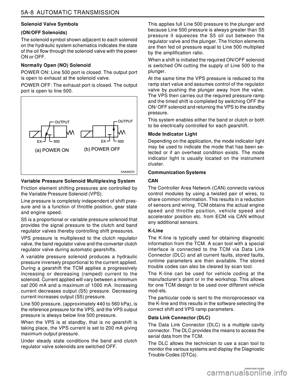
Normally Open (NO) Solenoid
POWER ON: Line 500 port is closed. The output port
is open to exhaust at the solenoid valve.
POWER OFF: The exhaust port is closed. The output
port is open to line 500.
Variable Pressure Solenoid Multiplexing System
Friction element shifting pressures are controlled by
the Variable Pressure Solenoid (VPS).
Line pressure is completely independent of shift pres-
sure and is a function of throttle position, gear state
and engine speed.
S5 is a proportional or variable pressure solenoid that
provides the signal pressure to the clutch and band
regulator valves thereby controlling shift pressures.
VPS pressure is multiplexed to the clutch regulator
valve, the band regulator valve and the converter clutch
regulator valve during automatic gearshifts.
A variable pressure solenoid produces a hydraulic
pressure inversely proportional to the current applied.
During a gearshift the TCM applies a progressively
increasing or decreasing (ramped) current to the
solenoid. Current applied will vary between a minimum
oaf 200 mA and a maximum of 1000 mA. Increasing
current decreases output (S5) pressure. Decreasing
current increases output (S5) pressure.
Line 500 pressure, (approximately 440 to 560 kPa), is
the reference pressure for the VPS, and the VPS output
pressure is always below line 500 pressure.
When the VPS is at standby, that is no gearshift is
taking place, the VPS current is set to 200 mA giving
maximum output pressure.
Under steady state conditions the band and clutch
regulator valve solenoids are switched OFF.This applies full Line 500 pressure to the plunger and
because Line 500 pressure is always greater than S5
pressure it squeezes the S5 oil out between the
regulator valve and the plunger. The friction elements
are then fed oil pressure equal to Line 500 multiplied
by the amplification ratio.
When a shift is initiated the required ON/OFF solenoid
is switched ON cutting the supply of Line 500 to the
plunger.
At the same time the VPS pressure is reduced to the
ramp start value and assumes control of the regulator
valve by pushing the plunger away from the valve.
The VPS then carries out the required pressure ramp
and the timed shift is completed by switching OFF the
ON/ OFF solenoid and returning the VPS to the standby
pressure.
This system enables either the band or clutch or both
to be electrically controlled for each gearshift.
Mode Indicator Light
Depending on the application, the mode indicator light
may be used to indicate the mode that has been se-
lected or if an overheat condition exists. The mode
indicator light is usually located on the instrument
cluster.
Communication Systems
CAN
The Controller Area Network (CAN) connects various
control modules by using a twisted pair of wires, to
share common information. This results in a reduction
of sensors and wiring. TCM obtains the actual engine
speed and throttle position, vehicle speed and
accelerator position etc. from ECM via CAN without
any additional sensors.
K-Line
The K-line is typically used for obtaining diagnostic
information from the TCM. A scan tool with a special
interface is connected to the TCM via Data Link
Connector (DLC) and all current faults, stored faults,
runtime parameters are then available. The stored
trouble codes can also be cleared by scan tool.
The K-line can be used for vehicle coding at the
manufacturer’s plant or in the workshop. This allows
for one TCM design to be used over different vehicle
mod-els.
The particular code is sent to the microprocessor via
the K-line and this results in the software selecting the
correct shift and VPS ramp parameters.
Data Link Connector (DLC)
The Data Link Connector (DLC) is a multiple cavity
connector. The DLC provides the means to access the
serial data from the TCM.
The DLC allows the technician to use a scan tool to
monitor the various systems and display the Diagnostic
Trouble Codes (DTCs).
KAA5A070
Page 1143 of 2053

5A-48 AUTOMATIC TRANSMISSION
SSANGYONG MY2002
TROUBLE CODE DIAGNOSIS - GASOLINE VEHICLE
TCM DIAGNOSTIC SYSTEM
OVERVIEW
Notice: To prevent Transmission Control Module (TCM)
damage. The ignition key must be OFF when
disconnection or reconnection the power to the TCM
(for example bttery cable, TCM pigtail connector, TCM
fuse, jumper cables, etc.).
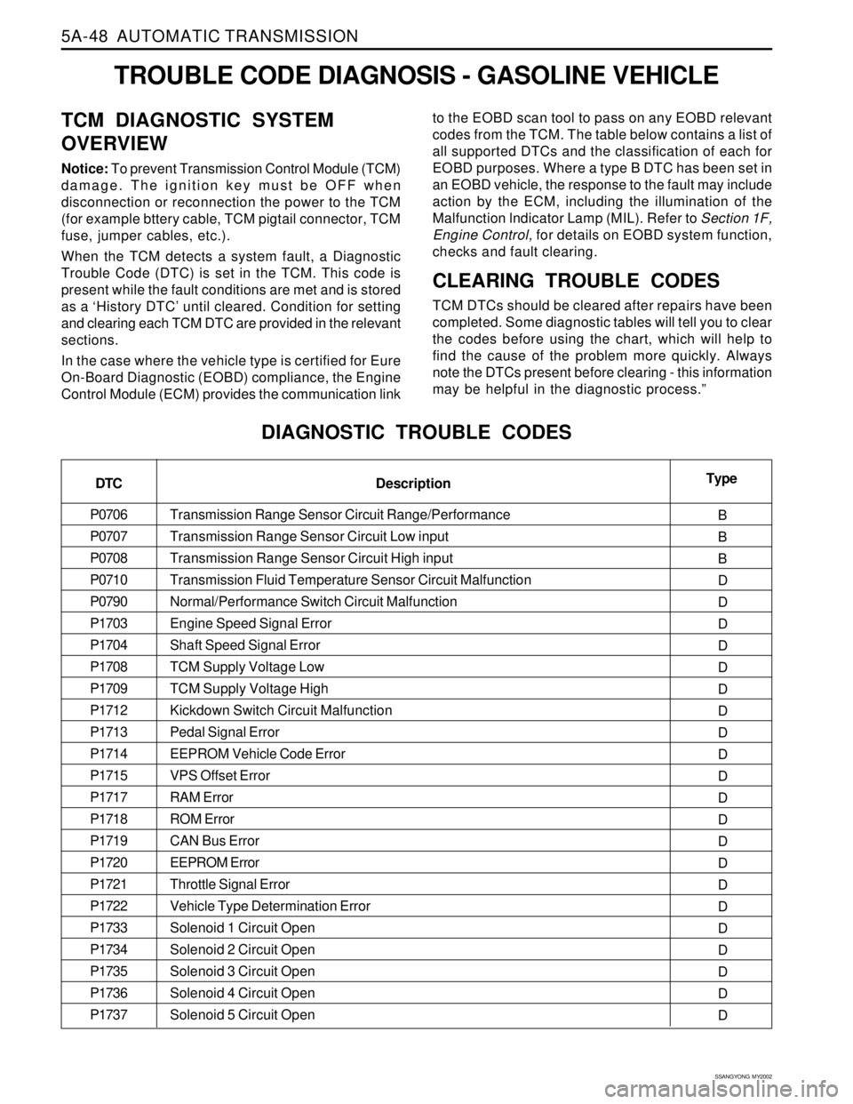
When the TCM detects a system fault, a Diagnostic
Trouble Code (DTC) is set in the TCM. This code is
present while the fault conditions are met and is stored
as a ‘History DTC’ until cleared. Condition for setting
and clearing each TCM DTC are provided in the relevant
sections.
In the case where the vehicle type is certified for Eure
On-Board Diagnostic (EOBD) compliance, the Engine
Control Module (ECM) provides the communication linkto the EOBD scan tool to pass on any EOBD relevant
codes from the TCM. The table below contains a list of
all supported DTCs and the classification of each for
EOBD purposes. Where a type B DTC has been set in
an EOBD vehicle, the response to the fault may include
action by the ECM, including the illumination of the
Malfunction lndicator Lamp (MIL). Refer to Section 1F,
Engine Control, for details on EOBD system function,
checks and fault clearing.
CLEARING TROUBLE CODES
TCM DTCs should be cleared after repairs have been
completed. Some diagnostic tables will tell you to clear
the codes before using the chart, which will help to
find the cause of the problem more quickly. Always
note the DTCs present before clearing - this information
may be helpful in the diagnostic process.”
DIAGNOSTIC TROUBLE CODES
DTC
P0706
P0707
P0708
P0710
P0790
P1703
P1704
P1708
P1709
P1712
P1713
P1714
P1715
P1717
P1718
P1719
P1720
P1721
P1722
P1733
P1734
P1735
P1736
P1737Type
B
B
B
D
D
D
D
D
D
D
D
D
D
D
D
D
D
D
D
D
D
D
D
D Description
Transmission Range Sensor Circuit Range/Performance
Transmission Range Sensor Circuit Low input
Transmission Range Sensor Circuit High input
Transmission Fluid Temperature Sensor Circuit Malfunction
Normal/Performance Switch Circuit Malfunction
Engine Speed Signal Error
Shaft Speed Signal Error
TCM Supply Voltage Low
TCM Supply Voltage High
Kickdown Switch Circuit Malfunction
Pedal Signal Error
EEPROM Vehicle Code Error
VPS Offset Error
RAM Error
ROM Error
CAN Bus Error
EEPROM Error
Throttle Signal Error
Vehicle Type Determination Error
Solenoid 1 Circuit Open
Solenoid 2 Circuit Open
Solenoid 3 Circuit Open
Solenoid 4 Circuit Open
Solenoid 5 Circuit Open