Page 1456 of 2053
POWER STEERING SYSTEM 6A-5
SSANGYONG MY2002
BLEEDING THE POWER
STEERING SYSTEM
1. Disconnect the fuel line. Using a starter motor,
crank the engine and turn the steering wheel from
lock to start 5 or 6 times.
Notice: Do bleeding with engine cranking. If bleed
with idling, there can be a air contact with oil.
2. Connect the fuel feed line and start the engine at
idle speed.
3. Turn the steering wheel from lock to lock until there
is no more air in oil reservoir.
4. Connect the oil level is within specification.
5. By turning the steering wheel left to right, check
the oil level change.
Notice: If oil is not changes more than 5 mm, do
bleeding again. If oil level rises suddenly when
stopped engine, again.
MAINTENANCE
CHECKING AND ADDING FLUID
Notice: When adding fluid or making a complete fluid
change, always use DEXRON. - II power steering fluid.
Failure to use the proper fluid will cause hose and seal
damage and fluid leaks.
1. The power steering fluid level is indicated by marks
on a fluid level indicator on the fluid reservoir cap.
2. If the fluid is warmed up to 66 °C (150 °F), the fluid
level should be between the MAX and MIN marks.
Add fluid as needed.
3. If the fluid is cool, 21 °C (70 °F), the fluid level should
be at the MIN mark. Add fluid as needed.
Page 1533 of 2053
SSANGYONG MY2002
7C-4 MANUAL & SEMIAUTO-HVAC
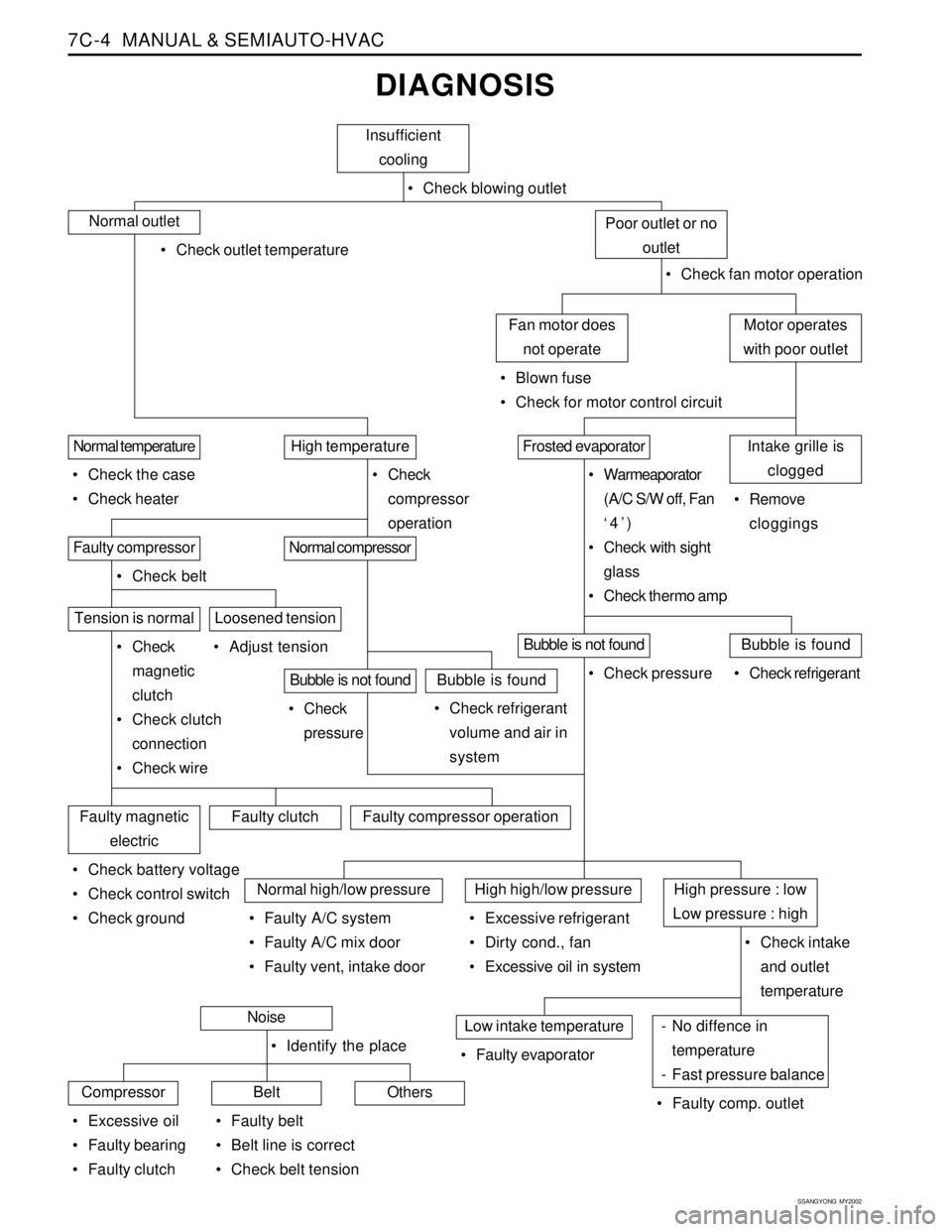
DIAGNOSIS
Insufficient
cooling
Check blowing outlet
Normal outlet
Check outlet temperature
Check fan motor operation
Motor operates
with poor outletFan motor does
not operate
Blown fuse
Check for motor control circuit
Poor outlet or no
outlet
Intake grille is
cloggedFrosted evaporatorHigh temperatureNormal temperature
Check the case
Check heater Check
compressor
operation Warmeaporator
(A/C S/W off, Fan
‘4’)
Check with sight
glass
Check thermo amp Remove
cloggings
Normal compressorFaulty compressor
Check belt
Tension is normal
Check
magnetic
clutch
Check clutch
connection
Check wire Adjust tension
Bubble is not foundBubble is found
Check refrigerant
volume and air in
system Check
pressure
Loosened tension
Bubble is not foundBubble is found
Check refrigerant Check pressure
Faulty magnetic
electricFaulty clutchFaulty compressor operation
Check battery voltage
Check control switch
Check ground
Normal high/low pressureHigh high/low pressureHigh pressure : low
Low pressure : high
Check intake
and outlet
temperature Faulty A/C system
Faulty A/C mix door
Faulty vent, intake door Excessive refrigerant
Dirty cond., fan
Excessive oil in system
- No diffence in
temperature
- Fast pressure balanceLow intake temperature
Faulty comp. outlet Faulty evaporatorNoise
CompressorBeltOthers
Excessive oil
Faulty bearing
Faulty clutch Identify the place
Faulty belt
Belt line is correct
Check belt tension
Page 1535 of 2053
SSANGYONG MY2002
7C-6 MANUAL & SEMIAUTO-HVAC
Oily clutch plate
Low voltage
Faulty electric connection or operationChecksActionClean oily plate using cleaning agent.
Charge battery or check for cause.
Check wire continuity
Check A/C switch and fan switch for continuity and
ground.
Magnetic Clutch Plays By Hand Only
Excessive clearance between
Clutch plate and clutch coilChecksActionAdjust clutch clearance (0.2-0.6mm).
DEFECTIVES IN COMPRESSOR CIRCUIT
Compressor Does Not Run
Faulty high/low pressure
Faulty A/C relayChecksActionCheck compressor magnet voltage supply.
A/C relay.
Magnetic Clutch Slips / Idles
Page 1536 of 2053
MANUAL & SEMIAUTO-HVAC 7C-7
SSANGYONG MY2002
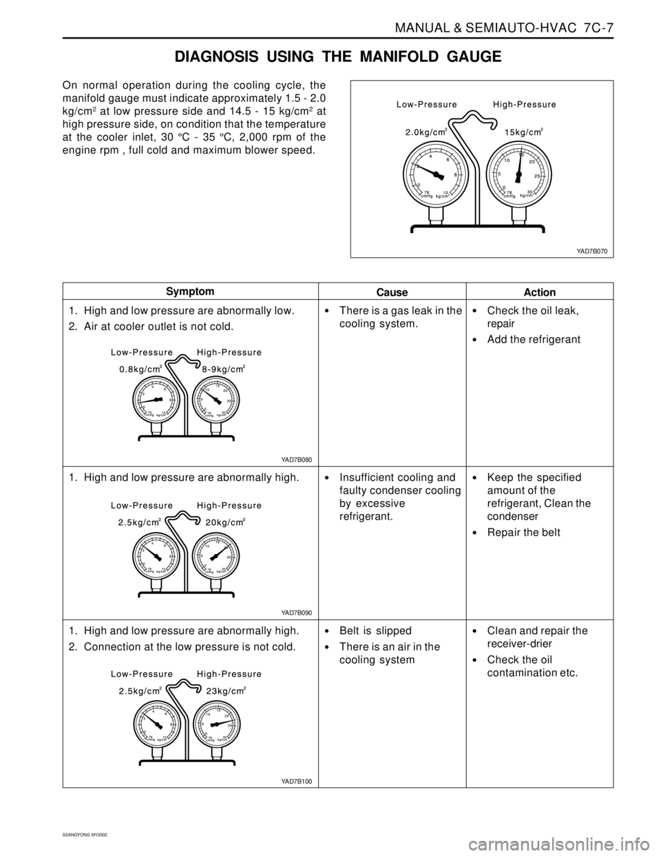
DIAGNOSIS USING THE MANIFOLD GAUGE
On normal operation during the cooling cycle, the
manifold gauge must indicate approximately 1.5 - 2.0
kg/cm
2 at low pressure side and 14.5 - 15 kg/cm2 at
high pressure side, on condition that the temperature
at the cooler inlet, 30 ºC - 35 ºC, 2,000 rpm of the
engine rpm , full cold and maximum blower speed.
Cause Symptom
Action
1. High and low pressure are abnormally low.
2. Air at cooler outlet is not cold.
1. High and low pressure are abnormally high.
1. High and low pressure are abnormally high.
2. Connection at the low pressure is not cold.
There is a gas leak in the
cooling system.
Insufficient cooling and
faulty condenser cooling
by excessive
refrigerant.
Belt is slipped
There is an air in the
cooling system
Check the oil leak,
repair
Add the refrigerant
Keep the specified
amount of the
refrigerant, Clean the
condenser
Repair the belt
Clean and repair the
receiver-drier
Check the oil
contamination etc.
YAD7B070
YAD7B080
YAD7B100 YAD7B090
Page 1537 of 2053
SSANGYONG MY2002
7C-8 MANUAL & SEMIAUTO-HVAC
1. The low-pressure and high-pressure are exces-
sive high.
2. There are a lot of moistures in the connection
of the low-side pressure
Cause SymptomAction
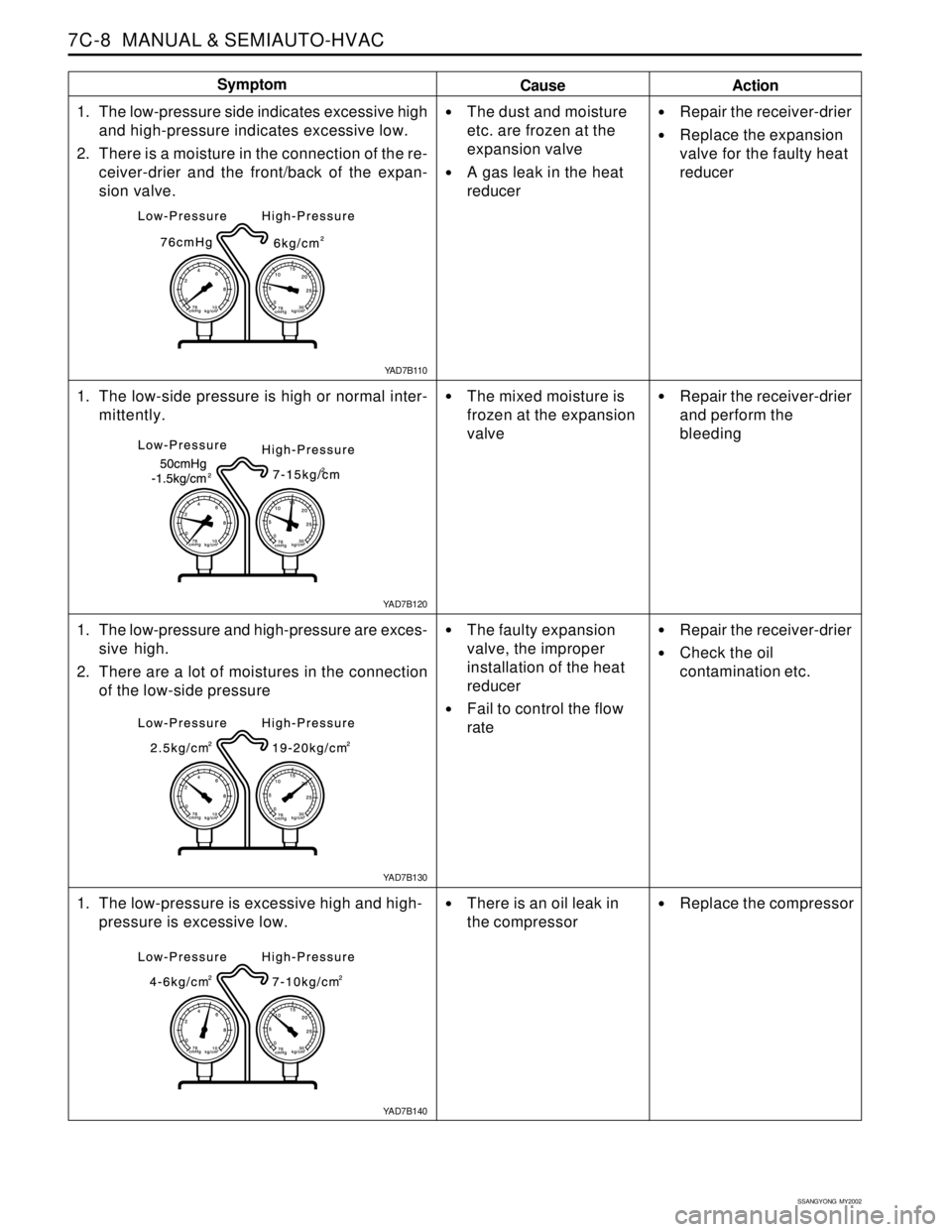
1. The low-pressure side indicates excessive high
and high-pressure indicates excessive low.
2. There is a moisture in the connection of the re-
ceiver-drier and the front/back of the expan-
sion valve.
1. The low-side pressure is high or normal inter-
mittently.
The dust and moisture
etc. are frozen at the
expansion valve
A gas leak in the heat
reducer
The mixed moisture is
frozen at the expansion
valve
The faulty expansion
valve, the improper
installation of the heat
reducer
Fail to control the flow
rate
Repair the receiver-drier
Replace the expansion
valve for the faulty heat
reducer
Repair the receiver-drier
and perform the
bleeding
Repair the receiver-drier
Check the oil
contamination etc.
1. The low-pressure is excessive high and high-
pressure is excessive low.
There is an oil leak in
the compressorReplace the compressor
YAD7B110
YAD7B130 YAD7B120
YAD7B140
Page 1543 of 2053
SSANGYONG MY2002
7C-14 MANUAL & SEMIAUTO-HVAC
REFRIGERANT CHARGING
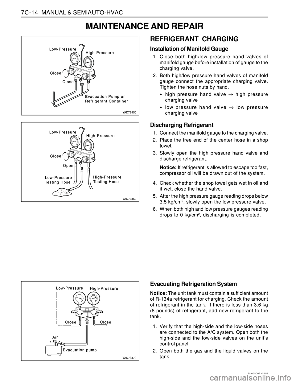
Installation of Manifold Gauge
1. Close both high/low pressure hand valves of
manifold gauge before installation of gauge to the
charging valve.
2. Both high/low pressure hand valves of manifold
gauge connect the appropriate charging valve.
Tighten the hose nuts by hand.
high pressure hand valve → high pressure
charging valve
low pressure hand valve → low pressure
charging valve
Discharging Refrigerant
1. Connect the manifold gauge to the charging valve.
2. Place the free end of the center hose in a shop
towel.
3. Slowly open the high pressure hand valve and
discharge refrigerant.
Notice: If refrigerant is allowed to escape too fast,
compressor oil will be drawn out of the system.
4. Check whether the shop towel gets wet in oil and
if wet, close the hand valve.
5. After the high pressure gauge reading drops below
3.5 kg/cm
2, slowly open the low pressure valve.
6. When both high and low pressure gauges reading
drops to 0 kg/cm
2, discharging is completed.
Evacuating Refrigeration System
Notice: The unit tank must contain a sufficient amount
of R-134a refrigerant for charging. Check the amount
of refrigerant in the tank. If there is less than 3.6 kg
(8 pounds) of refrigerant, add new refrigerant to the
tank.
1. Verify that the high-side and the low-side hoses
are connected to the A/C system. Open both the
high-side and the low-side valves on the unit’s
control panel.
2. Open both the gas and the liquid valves on the
tank.
YAD7B150
YAD7B160
YAD7B170
MAINTENANCE AND REPAIR
Page 1544 of 2053
MANUAL & SEMIAUTO-HVAC 7C-15
SSANGYONG MY2002
Important: Refer to the manufacturer’s
instructions for the charging station in use. It is
necessary to evacuate the system before
recharging it with new or recycled refrigerant.
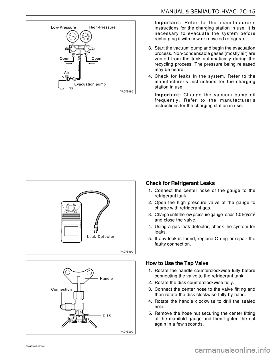
3. Start the vacuum pump and begin the evacuation
process. Non-condensable gases (mostly air) are
vented from the tank automatically during the
recycling process. The pressure being released
may be heard.
4. Check for leaks in the system. Refer to the
manufacturer’s instructions for the charging
station in use.
Important: Change the vacuum pump oil
frequently. Refer to the manufacturer’s
instructions for the charging station in use.
Check for Refrigerant Leaks
1. Connect the center hose of the gauge to the
refrigerant tank.
2. Open the high pressure valve of the gauge to
charge with refrigerant gas.
3. Charge until the low pressure gauge reads 1.0 kg/cm
2
and close the valve.
4. Using a gas leak detector, check the system for
leaks.
5. If any leak is found, replace O-ring or repair the
faulty connection.
How to Use the Tap Valve
1. Rotate the handle counterclockwise fully before
connecting the valve to the refrigerant tank.
2. Rotate the disk counterclockwise fully.
3. Connect the center hose to the valve fitting and
then rotate the disk clockwise fully by hand.
4. Rotate the handle clockwise to drill the sealed
hole.
5. Remove the hose nut securing the center fitting
of the manifold gauge and then tighten the nut
again in a few seconds.
YAD7B180
YAD7B190
YAD7B200
Page 1547 of 2053
SSANGYONG MY2002
7C-18 MANUAL & SEMIAUTO-HVAC
Total Oil Capacity 265 cc
COMPRESSOR OIL
REPLACEMENT
Before Oil Replacement
When any part is replaced or there are a lot of gas
leaks in the A/C system, you should add the specified
amount of the oil to keep the approval oil capacity
because the oil for lubricating the compressor
circulates through the A/C system during operating
the compressor.
Handling Oil
Be careful that moistures, dusts etc. must not flow
into the oil.
Do not mix with any other material.
If the oil leaves outside for long time, it’s possible
to mix it with the moistures and so keep the oil
sealed with a container.
Circulating Oil
For checking or adjusting the oil level, set the control
unit to full cold and max blower speed with keeping
the engine run at idle for 20 - 30 minutes in order to
circulate the oil through the compressor.