1997 SSANGYONG KORANDO check oil
[x] Cancel search: check oilPage 1311 of 2053
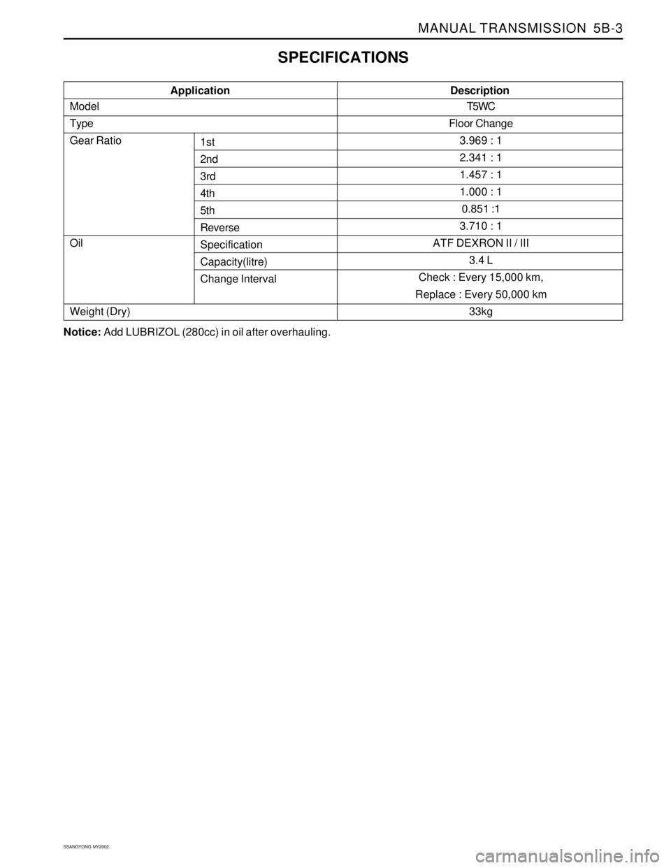
MANUAL TRANSMISSION 5B-3
SSANGYONG MY2002
Model
Type
Gear Ratio
Oil
Weight (Dry)1st
2nd
3rd
4th
5th
Reverse
Specification
Capacity(litre)
Change Interval Application
SPECIFICATIONS
T5WC
Floor Change
3.969 : 1
2.341 : 1
1.457 : 1
1.000 : 1
0.851 :1
3.710 : 1
ATF DEXRON II / III
3.4 L
Check : Every 15,000 km,
Replace : Every 50,000 km
33kg
Description
Notice: Add LUBRIZOL (280cc) in oil after overhauling.
Page 1312 of 2053
SSANGYONG MY2002
5B-4 MANUAL TRANSMISSION
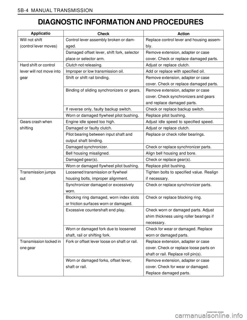
DIAGNOSTIC INFORMATION AND PROCEDURES
Control lever assembly broken or dam-
aged.
Damaged offset lever, shift fork, selector
place or selector arm.
Clutch not releasing.
Improper or low transmission oil.
Shift or shift rail binding.
Binding of sliding synchronizers or gears.
If reverse only, faulty backup switch.
Worn or damaged flywheel pilot bushing.
Engine idle speed too high.
Damaged or faulty clutch.
Pilot bearing between input shaft and
output shaft binding.
Damaged synchronizer.
Bell housing misaligned.
Damaged gear(s).
Worn or damaged flywheel pilot bushing.
Loosened transmission or flywheel
housing bolts, improper alignment.
Synchronizer damaged or excessively
worn.
Blocking ring damaged, worn index slots
or friction surfaces worn or damaged.
Excessive countershaft end play.
Worn or damaged fork due to loosened
shaft, rail or shifting fork.
Fork or offset lever loose on shaft or rail.
Worn or damaged forks, offset lever,
shaft or rail.Replace control lever and housing assem-
bly.
Remove extension, adapter or case
cover. Check or replace damaged parts.
Adjust or replace clutch.
Add or replace with specified oil.
Remove extension, adapter or case
cover. Check or replace damaged parts.
Remove extension, adapter or case
cover. Check synchronizers and gears
and replace damaged parts.
Check or replace backup switch.
Replace pilot bushing.
Adjust idle speed to specified speed.
Adjust or replace clutch.
Replace or check roller bearings.
Check or replace synchronizer parts.
Align bell housing and bore.
Check or replace gear(s).
Replace pilot bushing.
Tighten bolts to specified value. Realign
if necessary.
Check or replace synchronizer parts.
Check or replace blocking ring.
Check worn or damaged parts. Adjust
shim thickness using roller bearings if
necessary.
Check for wear or damaged. Replace
worn or damaged parts.
Replace extension, adapter or case
cover. Check or replace loose parts on
shaft or rail. Replace roll pin(s).
Remove extension, adapter or case
cover. Check for wear or damaged.
Replace damaged parts. Check Applicatio
Will not shift
(control lever moves)
Hard shift or control
lever will not move into
gear
Gears crash when
shifting
Transmission jumps
out
Transmission locked in
one gear
Action
Page 1313 of 2053
MANUAL TRANSMISSION 5B-5
SSANGYONG MY2002
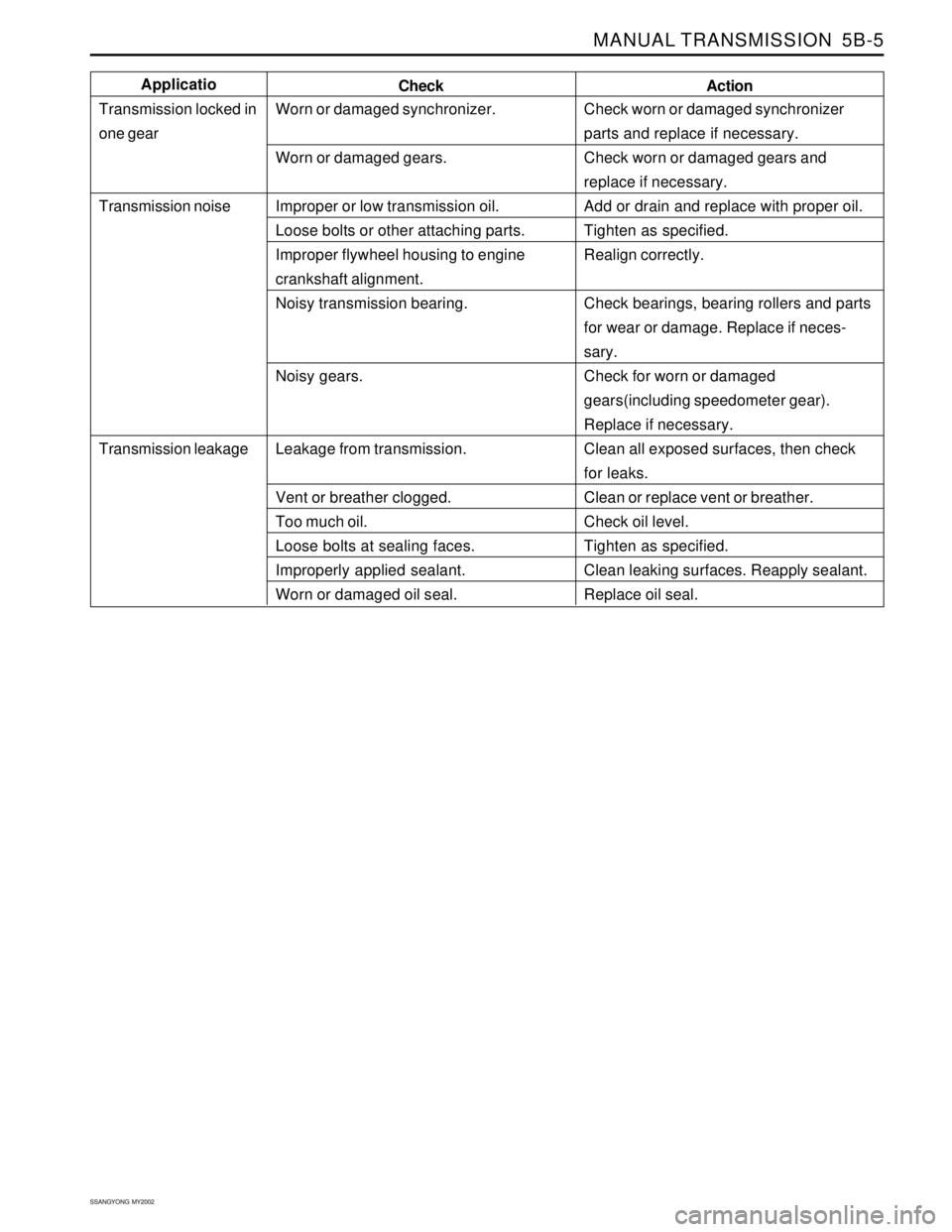
Check worn or damaged synchronizer
parts and replace if necessary.
Check worn or damaged gears and
replace if necessary.
Add or drain and replace with proper oil.
Tighten as specified.
Realign correctly.
Check bearings, bearing rollers and parts
for wear or damage. Replace if neces-
sary.
Check for worn or damaged
gears(including speedometer gear).
Replace if necessary.
Clean all exposed surfaces, then check
for leaks.
Clean or replace vent or breather.
Check oil level.
Tighten as specified.
Clean leaking surfaces. Reapply sealant.
Replace oil seal.
Action
Worn or damaged synchronizer.
Worn or damaged gears.
Improper or low transmission oil.
Loose bolts or other attaching parts.
Improper flywheel housing to engine
crankshaft alignment.
Noisy transmission bearing.
Noisy gears.
Leakage from transmission.
Vent or breather clogged.
Too much oil.
Loose bolts at sealing faces.
Improperly applied sealant.
Worn or damaged oil seal.Check Applicatio
Transmission locked in
one gear
Transmission noise
Transmission leakage
Page 1363 of 2053
SSAMGYONG MY2002
5C-8 CLUTCH
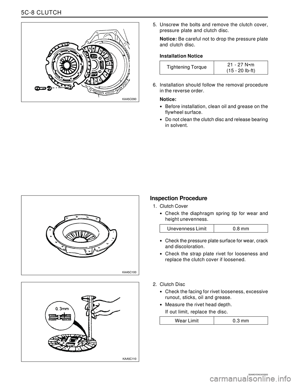
5. Unscrew the bolts and remove the clutch cover,
pressure plate and clutch disc.
Notice: Be careful not to drop the pressure plate
and clutch disc.
Installation Notice
6. Installation should follow the removal procedure
in the reverse order.
Notice:
Before installation, clean oil and grease on the
flywheel surface.
Do not clean the clutch disc and release bearing
in solvent.
2. Clutch Disc
Check the facing for rivet looseness, excessive
runout, sticks, oil and grease.
Measure the rivet head depth.
If out limit, replace the disc.
Inspection Procedure
1. Clutch Cover
Check the diaphragm spring tip for wear and
height unevenness.
Check the pressure plate surface for wear, crack
and discoloration.
Check the strap plate rivet for looseness and
replace the clutch cover if loosened.
KAA5C090
KAA5C100
KAA5C110
Tightening Torque21 - 27 Nm
(15 - 20 lb-ft)
Wear Limit 0.3 mm
Unevenness Limit 0.8 mm
Page 1369 of 2053
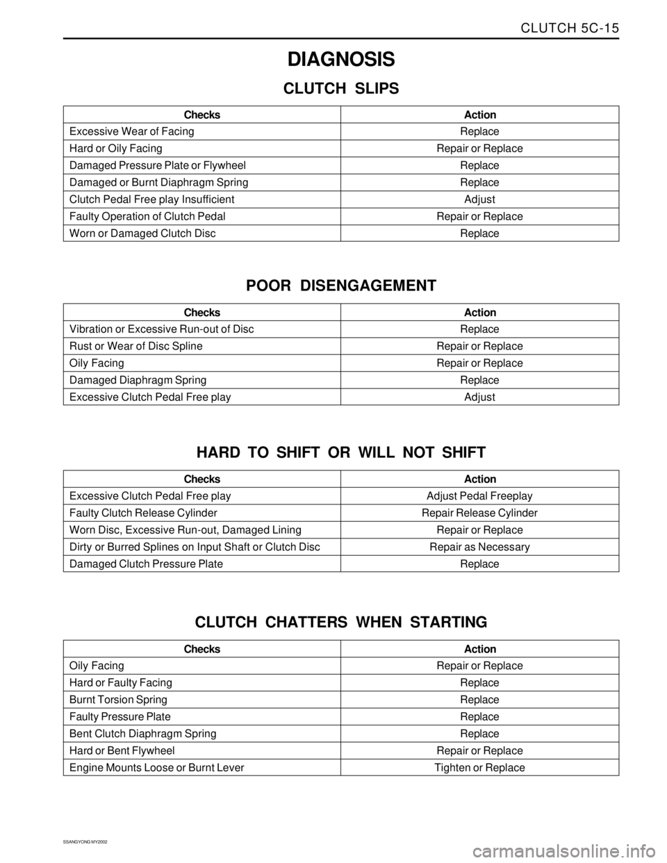
CLUTCH 5C-15
SSANGYONG MY2002
Replace
Repair or Replace
Replace
Replace
Adjust
Repair or Replace
Replace Excessive Wear of Facing
Hard or Oily Facing
Damaged Pressure Plate or Flywheel
Damaged or Burnt Diaphragm Spring
Clutch Pedal Free play Insufficient
Faulty Operation of Clutch Pedal
Worn or Damaged Clutch DiscAction Checks
DIAGNOSIS
CLUTCH SLIPS
Replace
Repair or Replace
Repair or Replace
Replace
Adjust Vibration or Excessive Run-out of Disc
Rust or Wear of Disc Spline
Oily Facing
Damaged Diaphragm Spring
Excessive Clutch Pedal Free playAction Checks
POOR DISENGAGEMENT
Adjust Pedal Freeplay
Repair Release Cylinder
Repair or Replace
Repair as Necessary
Replace Excessive Clutch Pedal Free play
Faulty Clutch Release Cylinder
Worn Disc, Excessive Run-out, Damaged Lining
Dirty or Burred Splines on Input Shaft or Clutch Disc
Damaged Clutch Pressure PlateAction Checks
HARD TO SHIFT OR WILL NOT SHIFT
Repair or Replace
Replace
Replace
Replace
Replace
Repair or Replace
Tighten or Replace Oily Facing
Hard or Faulty Facing
Burnt Torsion Spring
Faulty Pressure Plate
Bent Clutch Diaphragm Spring
Hard or Bent Flywheel
Engine Mounts Loose or Burnt LeverAction Checks
CLUTCH CHATTERS WHEN STARTING
Page 1372 of 2053
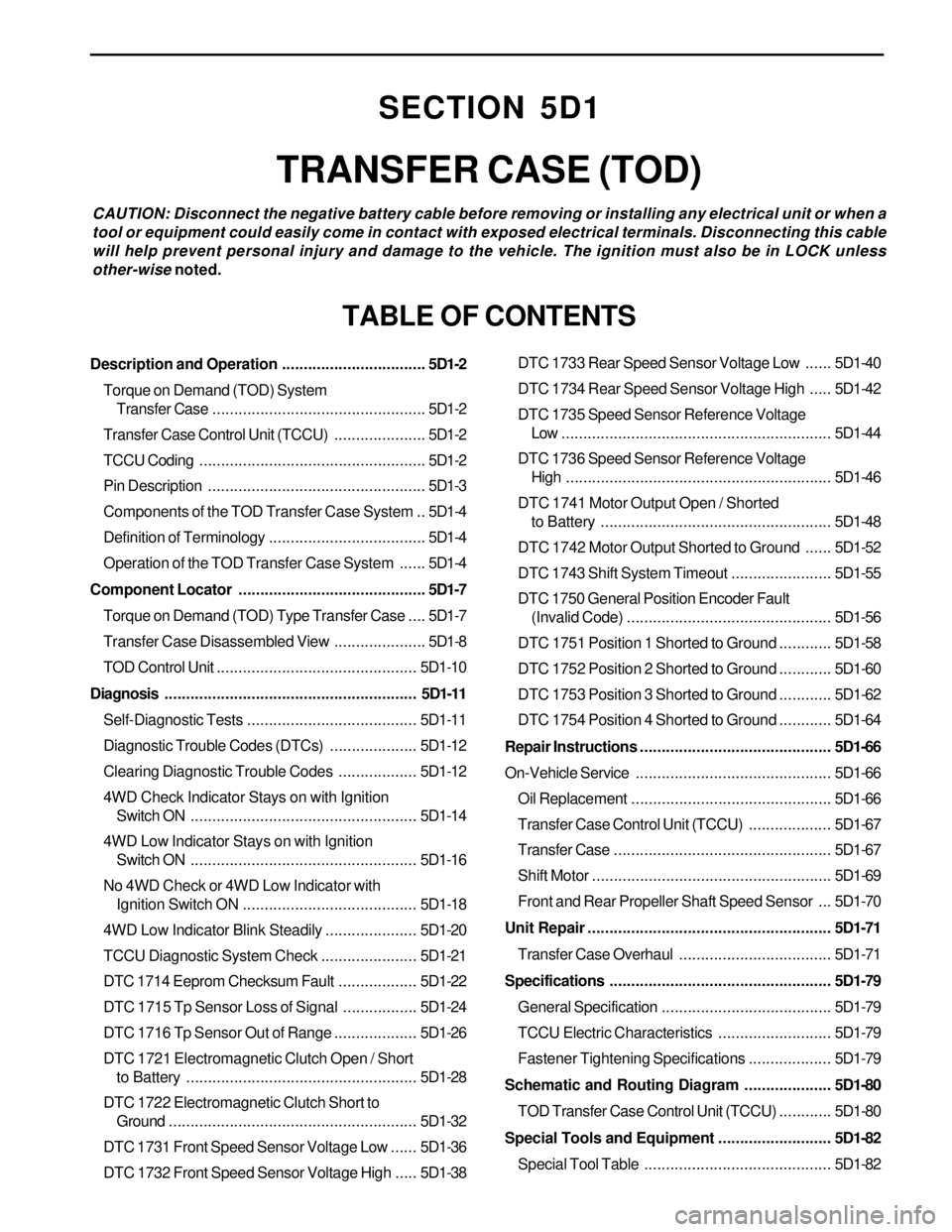
SECTION 5D1
TRANSFER CASE (TOD)
CAUTION: Disconnect the negative battery cable before removing or installing any electrical unit or when a
tool or equipment could easily come in contact with exposed electrical terminals. Disconnecting this cable
will help prevent personal injury and damage to the vehicle. The ignition must also be in LOCK unless
other-wise noted.
TABLE OF CONTENTS
Description and Operation.................................5D1-2
Torque on Demand (TOD) System
Transfer Case.................................................5D1-2
Transfer Case Control Unit (TCCU).....................5D1-2
TCCU Coding....................................................5D1-2
Pin Description..................................................5D1-3
Components of the TOD Transfer Case System ..5D1-4
Definition of Terminology....................................5D1-4
Operation of the TOD Transfer Case System......5D1-4
Component Locator...........................................5D1-7
Torque on Demand (TOD) Type Transfer Case....5D1-7
Transfer Case Disassembled View.....................5D1-8
TOD Control Unit..............................................5D1-10
Diagnosis..........................................................5D1-11
Self-Diagnostic Tests.......................................5D1-11
Diagnostic Trouble Codes (DTCs)....................5D1-12
Clearing Diagnostic Trouble Codes..................5D1-12
4WD Check Indicator Stays on with Ignition
Switch ON....................................................5D1-14
4WD Low Indicator Stays on with Ignition
Switch ON....................................................5D1-16
No 4WD Check or 4WD Low Indicator with
Ignition Switch ON........................................5D1-18
4WD Low Indicator Blink Steadily.....................5D1-20
TCCU Diagnostic System Check......................5D1-21
DTC 1714 Eeprom Checksum Fault..................5D1-22
DTC 1715 Tp Sensor Loss of Signal.................5D1-24
DTC 1716 Tp Sensor Out of Range...................5D1-26
DTC 1721 Electromagnetic Clutch Open / Short
to Battery.....................................................5D1-28
DTC 1722 Electromagnetic Clutch Short to
Ground.........................................................5D1-32
DTC 1731 Front Speed Sensor Voltage Low......5D1-36
DTC 1732 Front Speed Sensor Voltage High.....5D1-38DTC 1733 Rear Speed Sensor Voltage Low......5D1-40
DTC 1734 Rear Speed Sensor Voltage High.....5D1-42
DTC 1735 Speed Sensor Reference Voltage
Low ..............................................................5D1-44
DTC 1736 Speed Sensor Reference Voltage
High.............................................................5D1-46
DTC 1741 Motor Output Open / Shorted
to Battery.....................................................5D1-48
DTC 1742 Motor Output Shorted to Ground......5D1-52
DTC 1743 Shift System Timeout.......................5D1-55
DTC 1750 General Position Encoder Fault
(Invalid Code)...............................................5D1-56
DTC 1751 Position 1 Shorted to Ground............5D1-58
DTC 1752 Position 2 Shorted to Ground............5D1-60
DTC 1753 Position 3 Shorted to Ground............5D1-62
DTC 1754 Position 4 Shorted to Ground............5D1-64
Repair Instructions............................................5D1-66
On-Vehicle Service.............................................5D1-66
Oil Replacement..............................................5D1-66
Transfer Case Control Unit (TCCU)...................5D1-67
Transfer Case..................................................5D1-67
Shift Motor.......................................................5D1-69
Front and Rear Propeller Shaft Speed Sensor ...5D1-70
Unit Repair........................................................5D1-71
Transfer Case Overhaul...................................5D1-71
Specifications...................................................5D1-79
General Specification.......................................5D1-79
TCCU Electric Characteristics..........................5D1-79
Fastener Tightening Specifications...................5D1-79
Schematic and Routing Diagram....................5D1-80
TOD Transfer Case Control Unit (TCCU)............5D1-80
Special Tools and Equipment..........................5D1-82
Special Tool Table ...........................................5D1-82
Page 1388 of 2053
SSANGYONG MY2002
5D1-66 TRANSFER CASE
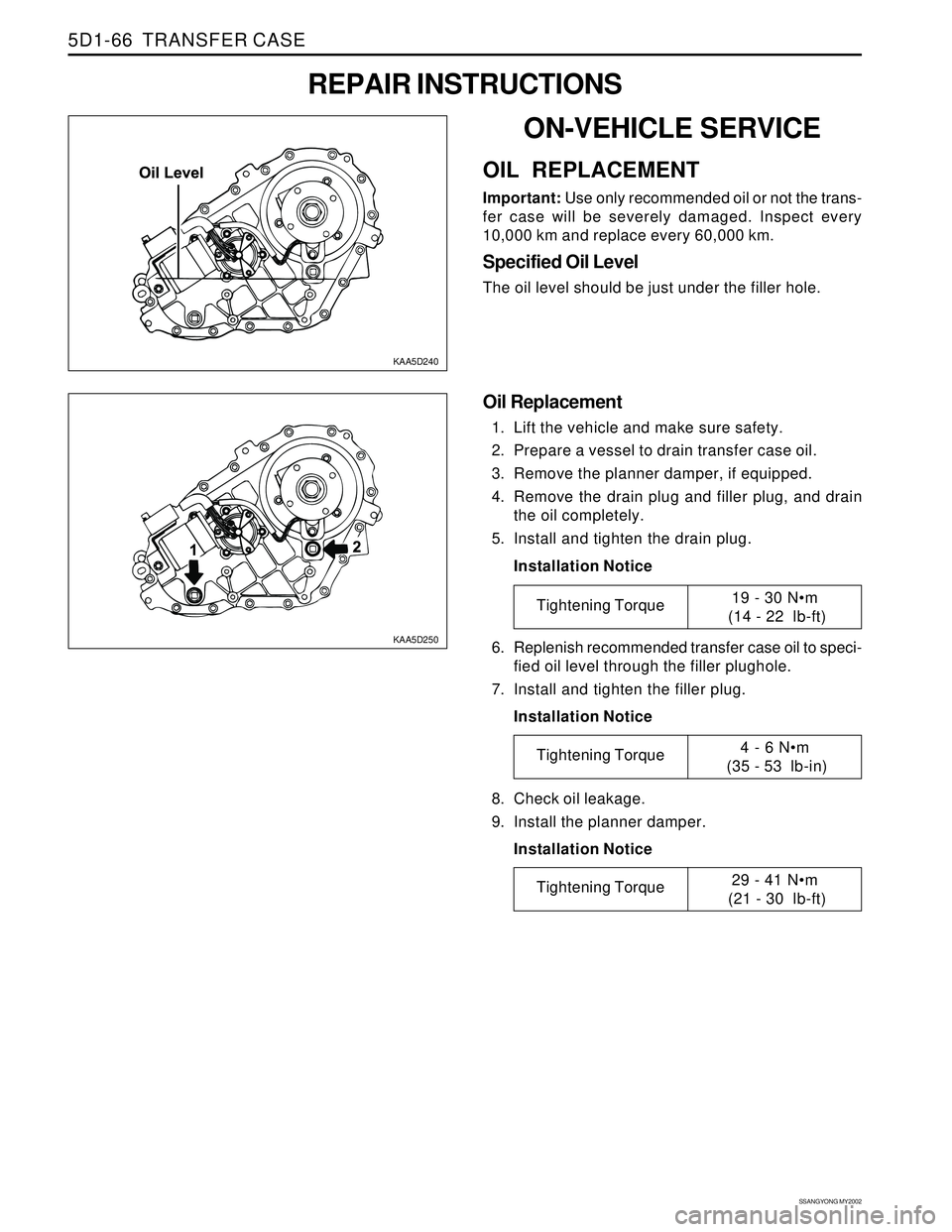
KAA5D240
KAA5D250
ON-VEHICLE SERVICE
OIL REPLACEMENT
Important: Use only recommended oil or not the trans-
fer case will be severely damaged. Inspect every
10,000 km and replace every 60,000 km.
Specified Oil Level
The oil level should be just under the filler hole.
REPAIR INSTRUCTIONS
Oil Replacement
1. Lift the vehicle and make sure safety.
2. Prepare a vessel to drain transfer case oil.
3. Remove the planner damper, if equipped.
4. Remove the drain plug and filler plug, and drain
the oil completely.
5. Install and tighten the drain plug.
Installation Notice
6. Replenish recommended transfer case oil to speci-
fied oil level through the filler plughole.
7. Install and tighten the filler plug.
Installation Notice
8. Check oil leakage.
9. Install the planner damper.
Installation Notice
Tightening Torque19 - 30 Nm
(14 - 22 lb-ft)
Tightening Torque4 - 6 Nm
(35 - 53 lb-in)
Tightening Torque29 - 41 Nm
(21 - 30 lb-ft)
Page 1395 of 2053
TRANSFER CASE 5D1-73
SSANGYONG MY2002
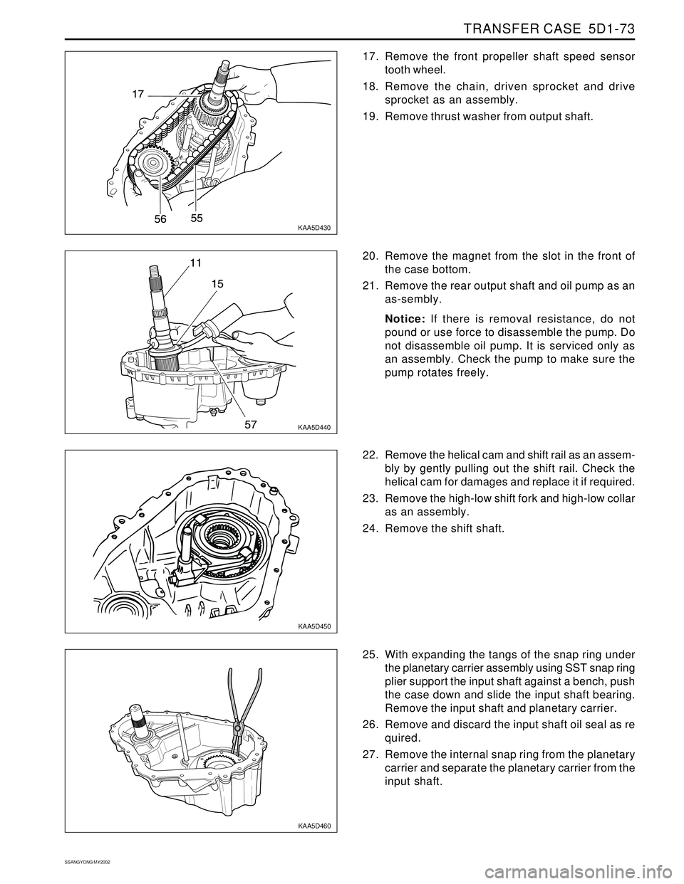
KAA5D430
KAA5D440
KAA5D450
KAA5D460
17. Remove the front propeller shaft speed sensor
tooth wheel.
18. Remove the chain, driven sprocket and drive
sprocket as an assembly.
19. Remove thrust washer from output shaft.
25. With expanding the tangs of the snap ring under
the planetary carrier assembly using SST snap ring
plier support the input shaft against a bench, push
the case down and slide the input shaft bearing.
Remove the input shaft and planetary carrier.
26. Remove and discard the input shaft oil seal as re
quired.
27. Remove the internal snap ring from the planetary
carrier and separate the planetary carrier from the
input shaft. 22. Remove the helical cam and shift rail as an assem-
bly by gently pulling out the shift rail. Check the
helical cam for damages and replace it if required.
23. Remove the high-low shift fork and high-low collar
as an assembly.
24. Remove the shift shaft. 20. Remove the magnet from the slot in the front of
the case bottom.
21. Remove the rear output shaft and oil pump as an
as-sembly.
Notice: If there is removal resistance, do not
pound or use force to disassemble the pump. Do
not disassemble oil pump. It is serviced only as
an assembly. Check the pump to make sure the
pump rotates freely.