1997 SSANGYONG KORANDO check oil
[x] Cancel search: check oilPage 952 of 2053

SSANGYONG MY2002
4D-2 FRONT BRAKES
DESCRIPTION AND OPERATION
GENERAL DESCRIPTION
When the brakes are applied, fluid pressure is sent to
each brake caliper. The pressure at the caliper is ex-
erted equally against the caliper piston. The pressure
applied to the piston is transmitted directly to the
inboard brake pad. This forces the pad against the inner
surface of the brake rotor. At the same time, fluid
pressure within the caliper piston bore forces the caliper
to slide inward on its guide pins. This action brings the
outboard pad into contact with the outer surface of the
brake rotor. This pressure on both sides of the brake
rotor causes friction, bringing the vehicle to a stop.
BRAKE CALIPER
The caliper has a single bore and is mounted to the
steering knuckle with two mounting bolts. Hydraulic
pressure, created by applying the brake pedal, is con-
verted by the caliper to a stopping force. This force
acts equally against the piston and the bottom of the
caliper bore to move the piston outward and to slide
the caliper inward, resulting in a clamping action on
the rotor. This clamping action forces the linings against
the rotor, creating friction to stop the vehicle.Important:
•Replace all components included in the repair kits
used to service the caliper.
Lubricate the rubber parts with clean brake fluid to
ease assembly.
Do not use lubricated shop air on brake parts, as
damage to the rubber components may result.
If any hydraulic component is removed or discon-
nected, it may be necessary to bleed all or part of
the brake system. Refer to Section 4F, Antilock
Brake System And Traction Control System.
Replace the pads in axle sets only.
The torque values specified are for dry, unlubricated
fasteners.
Perform the service operations on a clean bench,
free from all oily material.
BRAKE PADS
There are two brake pads mounted to each caliper, one
inboard and one outboard. As front disc brake pad wear,
master cylinder reservoir brake fluid level will drop. Fluid
level should be checked after replacing pads.
BRAKE ROTOR
Each front disc brake rotor is vented to help cool it dur-
ing and after brake applications.
Page 973 of 2053

REAR BRAKES 4E-13
SSANGYONG MY2002
5. Disconnect the parking brake cable from the
parking brake lever.
6. Remove the brake disc.
7. Using the rubber hammer, hit to separate the
parking brake lining lightly and move the lining
upward.
Inspection
1. Clean the dissembled parts and visually check
the followings;
Wear, rust and damage on the cylinder and
piston
Damage, crack on the caliper body and
damage, wear on the guide pin
Pad uneven wear and oil contamination
Boot’s damage and tear
YAD4C160
YAD4C170
YAD4C180
YAD4C190
Page 1002 of 2053
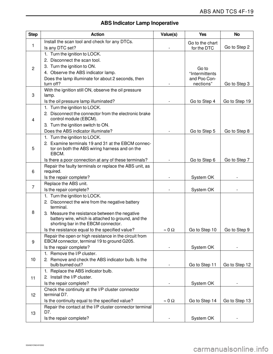
ABS AND TCS 4F-19
SSANGYONG MY2002
Step
1
2
3
4
5
6
7
8
9
10
11
12
13
ABS Indicator Lamp Inoperative
Action Yes
Go to the chart
for the DTC
Go to
“Intermittents
and Poo Con-
nections”
Go to Step 4
Go to Step 5
Go to Step 6
System OK
System OK
Go to Step 10
System OK
Go to Step 11
System OK
Go to Step 14
System OKNo
Go to Step 2
Go to Step 3
Go to Step 19
Go to Step 8
Go to Step 7
-
-
Go to Step 9
-
Go to Step 12
-
Go to Step 13
- Value(s)
Install the scan tool and check for any DTCs.
Is any DTC set?
1. Turn the ignition to LOCK.
2. Disconnect the scan tool.
3. Turn the ignition to ON.
4. Observe the ABS indicator lamp.
Does the lamp illuminate for about 2 seconds, then
turn off?
With the ignition still ON, observe the oil pressure
lamp.
Is the oil pressure lamp illuminated?
1. Turn the ignition to LOCK.
2. Disconnect the connector from the electronic brake
control module (EBCM).
3. Turn the ignition switch to ON.
Does the ABS indicator illuminate?
1. Turn the ignition to LOCK.
2. Examine terminals 19 and 31 at the EBCM connec-
tor on both the ABS wiring harness and on the
EBCM.
Is there a poor connection at any of these terminals?
Repair the faulty terminals or replace the ABS unit, as
required.
Is the repair complete?
Replace the ABS unit.
Is the repair complete?
1. Turn the ignition to LOCK.
2. Disconnect the wire from the negative battery
terminal.
3. Measure the resistance between the negative
battery wire, which is attached to ground, and the
shorting bar in the EBCM connector.
Is the resistance equal to the specified value?
Repair the open or high resistance in the circuit from
EBCM connector, terminal 19 to ground G205.
Is the repair complete?
1. Remove the I/P cluster.
2. Remove and check the ABS indicator bulb. Is the
bulb burned out?
1. Replace the ABS indicator bulb.
2. Install the I/P cluster.
Is the repair complete?
Check the continuity at the I/P cluster connector
terminal D7.
Is the continuity equal to the specified value?
Repair the contact at the I/P cluster connector terminal
D7.
Is the repair complete?
-
-
-
-
-
-
-
≈ 0 Ω
-
-
-
≈ 0 Ω
-
Page 1006 of 2053
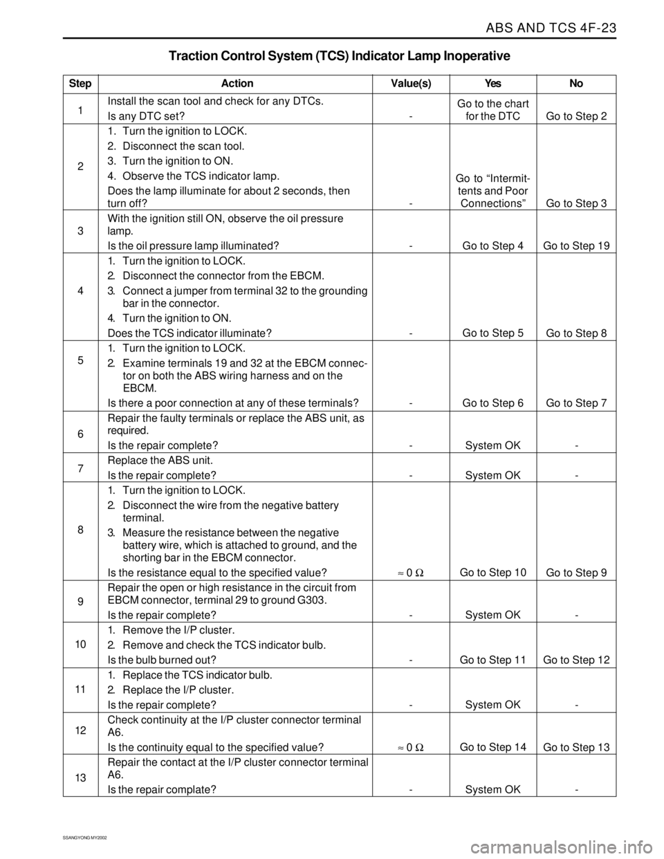
ABS AND TCS 4F-23
SSANGYONG MY2002
Step
1
2
3
4
5
6
7
8
9
10
11
12
13
Traction Control System (TCS) Indicator Lamp Inoperative
Action Yes NoValue(s)
Install the scan tool and check for any DTCs.
Is any DTC set?
1. Turn the ignition to LOCK.
2. Disconnect the scan tool.
3. Turn the ignition to ON.
4. Observe the TCS indicator lamp.
Does the lamp illuminate for about 2 seconds, then
turn off?
With the ignition still ON, observe the oil pressure
lamp.
Is the oil pressure lamp illuminated?
1. Turn the ignition to LOCK.
2. Disconnect the connector from the EBCM.
3. Connect a jumper from terminal 32 to the grounding
bar in the connector.
4. Turn the ignition to ON.
Does the TCS indicator illuminate?
1. Turn the ignition to LOCK.
2. Examine terminals 19 and 32 at the EBCM connec-
tor on both the ABS wiring harness and on the
EBCM.
Is there a poor connection at any of these terminals?
Repair the faulty terminals or replace the ABS unit, as
required.
Is the repair complete?
Replace the ABS unit.
Is the repair complete?
1. Turn the ignition to LOCK.
2. Disconnect the wire from the negative battery
terminal.
3. Measure the resistance between the negative
battery wire, which is attached to ground, and the
shorting bar in the EBCM connector.
Is the resistance equal to the specified value?
Repair the open or high resistance in the circuit from
EBCM connector, terminal 29 to ground G303.
Is the repair complete?
1. Remove the I/P cluster.
2. Remove and check the TCS indicator bulb.
Is the bulb burned out?
1. Replace the TCS indicator bulb.
2. Replace the I/P cluster.
Is the repair complete?
Check continuity at the I/P cluster connector terminal
A6.
Is the continuity equal to the specified value?
Repair the contact at the I/P cluster connector terminal
A6.
Is the repair complate?
-
-
-
-
-
-
-
≈ 0 Ω
-
-
-
≈ 0 Ω
-Go to the chart
for the DTC
Go to “Intermit-
tents and Poor
Connections”
Go to Step 4
Go to Step 5
Go to Step 6
System OK
System OK
Go to Step 10
System OK
Go to Step 11
System OK
Go to Step 14
System OKGo to Step 2
Go to Step 3
Go to Step 19
Go to Step 8
Go to Step 7
-
-
Go to Step 9
-
Go to Step 12
-
Go to Step 13
-
Page 1010 of 2053
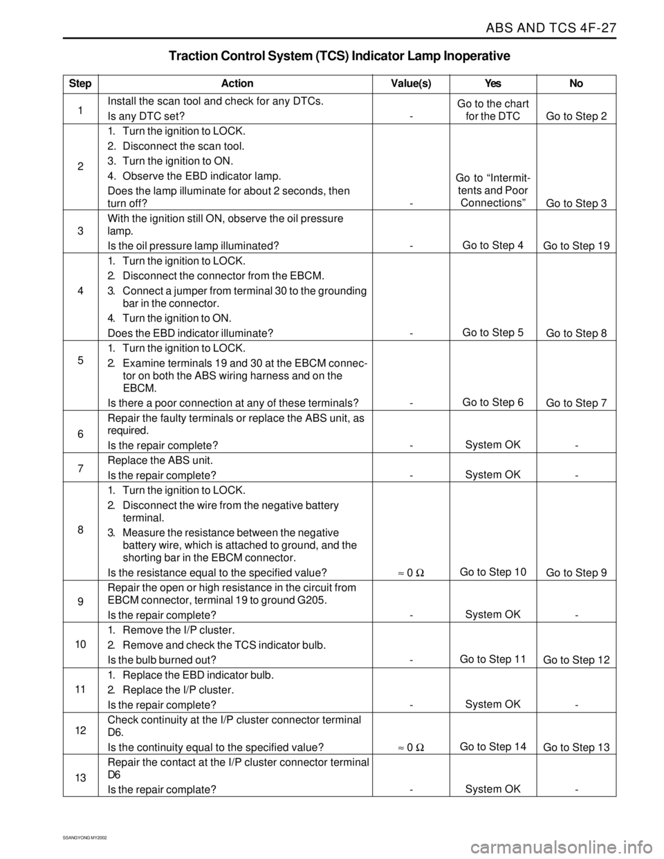
ABS AND TCS 4F-27
SSANGYONG MY2002
Step
1
2
3
4
5
6
7
8
9
10
11
12
13
Traction Control System (TCS) Indicator Lamp Inoperative
Action
Go to the chart
for the DTC
Go to “Intermit-
tents and Poor
Connections”
Go to Step 4
Go to Step 5
Go to Step 6
System OK
System OK
Go to Step 10
System OK
Go to Step 11
System OK
Go to Step 14
System OKGo to Step 2
Go to Step 3
Go to Step 19
Go to Step 8
Go to Step 7
-
-
Go to Step 9
-
Go to Step 12
-
Go to Step 13
- Value(s)
Install the scan tool and check for any DTCs.
Is any DTC set?
1. Turn the ignition to LOCK.
2. Disconnect the scan tool.
3. Turn the ignition to ON.
4. Observe the EBD indicator lamp.
Does the lamp illuminate for about 2 seconds, then
turn off?
With the ignition still ON, observe the oil pressure
lamp.
Is the oil pressure lamp illuminated?
1. Turn the ignition to LOCK.
2. Disconnect the connector from the EBCM.
3. Connect a jumper from terminal 30 to the grounding
bar in the connector.
4. Turn the ignition to ON.
Does the EBD indicator illuminate?
1. Turn the ignition to LOCK.
2. Examine terminals 19 and 30 at the EBCM connec-
tor on both the ABS wiring harness and on the
EBCM.
Is there a poor connection at any of these terminals?
Repair the faulty terminals or replace the ABS unit, as
required.
Is the repair complete?
Replace the ABS unit.
Is the repair complete?
1. Turn the ignition to LOCK.
2. Disconnect the wire from the negative battery
terminal.
3. Measure the resistance between the negative
battery wire, which is attached to ground, and the
shorting bar in the EBCM connector.
Is the resistance equal to the specified value?
Repair the open or high resistance in the circuit from
EBCM connector, terminal 19 to ground G205.
Is the repair complete?
1. Remove the I/P cluster.
2. Remove and check the TCS indicator bulb.
Is the bulb burned out?
1. Replace the EBD indicator bulb.
2. Replace the I/P cluster.
Is the repair complete?
Check continuity at the I/P cluster connector terminal
D6.
Is the continuity equal to the specified value?
Repair the contact at the I/P cluster connector terminal
D6
Is the repair complate?
-
-
-
-
-
-
-
≈ 0 Ω
-
-
-
≈ 0 Ω
-Yes No
Page 1045 of 2053
SSANGYONG MY2002
4F-62 ABS AND TCS
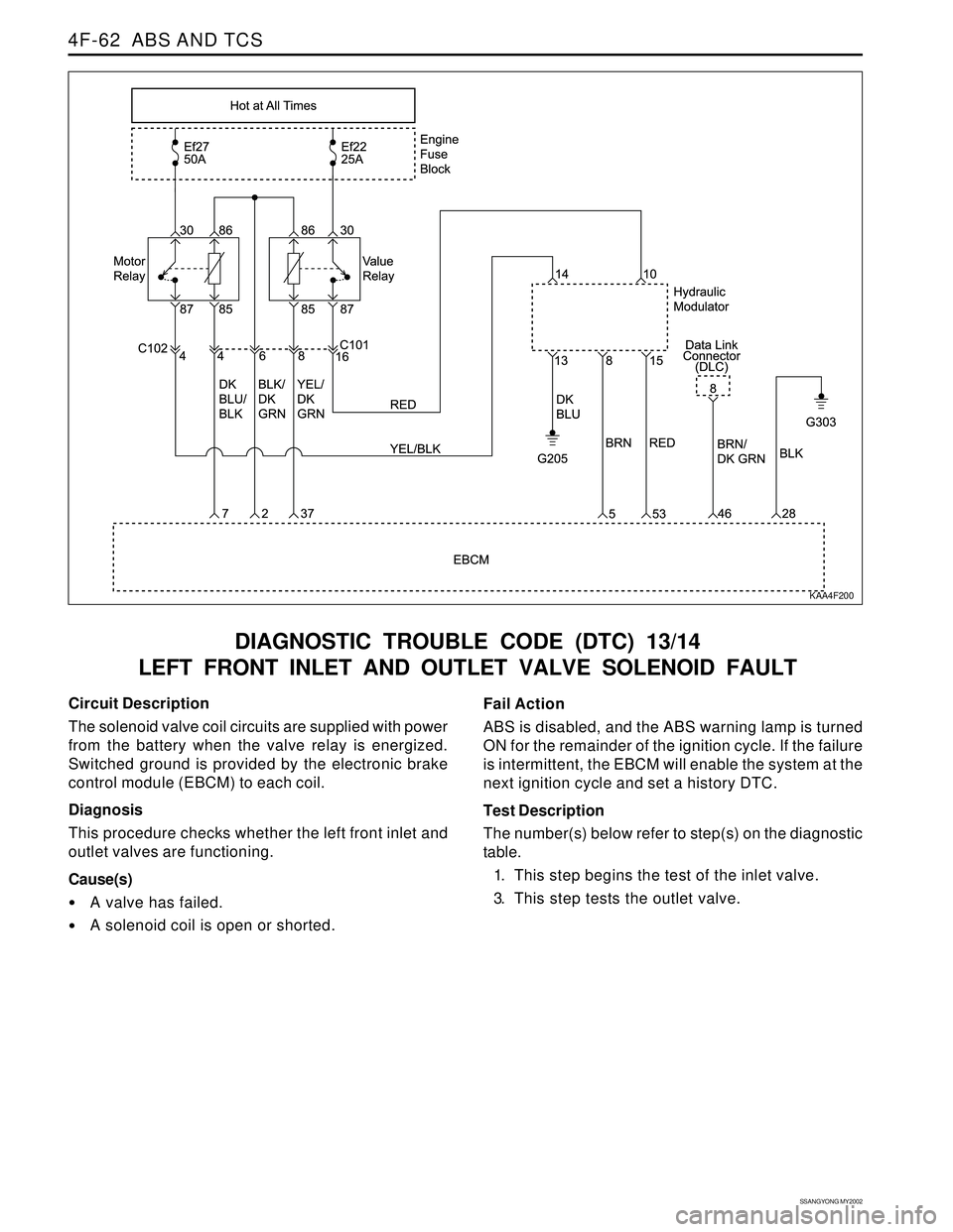
DIAGNOSTIC TROUBLE CODE (DTC) 13/14
LEFT FRONT INLET AND OUTLET VALVE SOLENOID FAULT
KAA4F200
Circuit Description
The solenoid valve coil circuits are supplied with power
from the battery when the valve relay is energized.
Switched ground is provided by the electronic brake
control module (EBCM) to each coil.
Diagnosis
This procedure checks whether the left front inlet and
outlet valves are functioning.
Cause(s)
A valve has failed.
A solenoid coil is open or shorted.Fail Action
ABS is disabled, and the ABS warning lamp is turned
ON for the remainder of the ignition cycle. If the failure
is intermittent, the EBCM will enable the system at the
next ignition cycle and set a history DTC.
Test Description
The number(s) below refer to step(s) on the diagnostic
table.
1. This step begins the test of the inlet valve.
3. This step tests the outlet valve.
Page 1047 of 2053
SSANGYONG MY2002
4F-64 ABS AND TCS
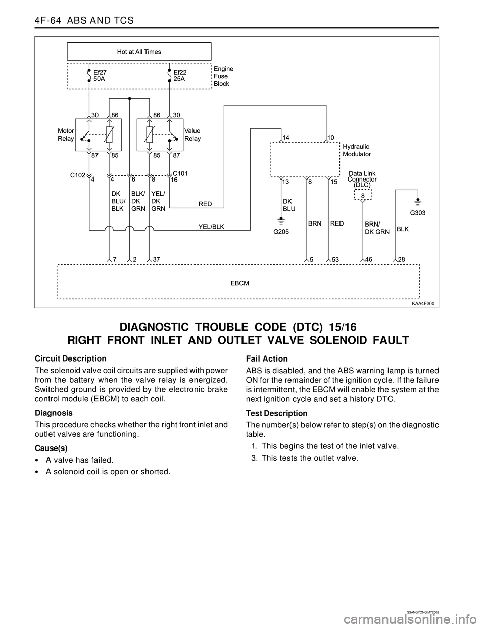
DIAGNOSTIC TROUBLE CODE (DTC) 15/16
RIGHT FRONT INLET AND OUTLET VALVE SOLENOID FAULT
KAA4F200
Circuit Description
The solenoid valve coil circuits are supplied with power
from the battery when the valve relay is energized.
Switched ground is provided by the electronic brake
control module (EBCM) to each coil.
Diagnosis
This procedure checks whether the right front inlet and
outlet valves are functioning.
Cause(s)
A valve has failed.
A solenoid coil is open or shorted.Fail Action
ABS is disabled, and the ABS warning lamp is turned
ON for the remainder of the ignition cycle. If the failure
is intermittent, the EBCM will enable the system at the
next ignition cycle and set a history DTC.
Test Description
The number(s) below refer to step(s) on the diagnostic
table.
1. This begins the test of the inlet valve.
3. This tests the outlet valve.
Page 1049 of 2053
SSANGYONG MY2002
4F-66 ABS AND TCS
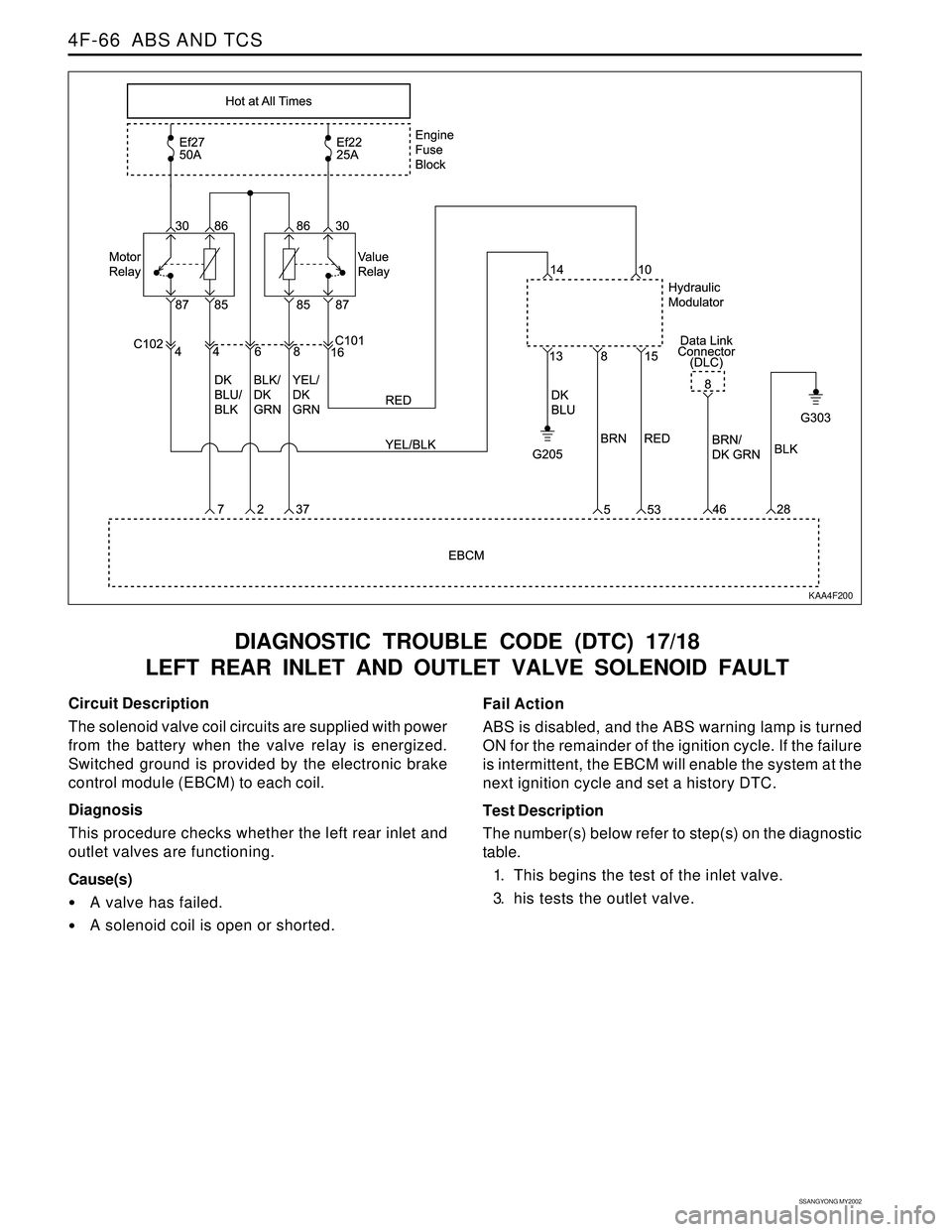
DIAGNOSTIC TROUBLE CODE (DTC) 17/18
LEFT REAR INLET AND OUTLET VALVE SOLENOID FAULT
KAA4F200
Circuit Description
The solenoid valve coil circuits are supplied with power
from the battery when the valve relay is energized.
Switched ground is provided by the electronic brake
control module (EBCM) to each coil.
Diagnosis
This procedure checks whether the left rear inlet and
outlet valves are functioning.
Cause(s)
A valve has failed.
A solenoid coil is open or shorted.Fail Action
ABS is disabled, and the ABS warning lamp is turned
ON for the remainder of the ignition cycle. If the failure
is intermittent, the EBCM will enable the system at the
next ignition cycle and set a history DTC.
Test Description
The number(s) below refer to step(s) on the diagnostic
table.
1. This begins the test of the inlet valve.
3. his tests the outlet valve.