1997 SSANGYONG KORANDO ignition switch
[x] Cancel search: ignition switchPage 1080 of 2053
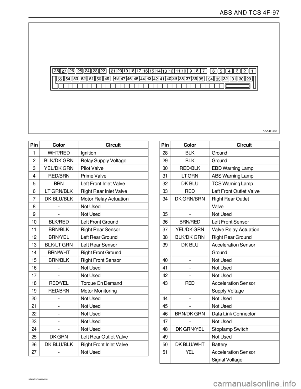
ABS AND TCS 4F-97
SSANGYONG MY2002
KAA4F320
Color
WHT/RED
BLK/DK GRN
YEL/DK GRN
RED/BRN
BRN
LT GRN/BLK
DK BLU/BLK
-
-
BLK/RED
BRN/BLK
BRN/YEL
BLK/LT GRN
BRN/WHT
BRN/BLK
-
-
RED/YEL
RED/BRN
-
-
-
-
-
DK GRN
DK BLU/BLK
- Pin
1
2
3
4
5
6
7
8
9
10
11
12
13
14
15
16
17
18
19
20
21
22
23
24
25
26
27Circuit
Ignition
Relay Supply Voltage
Pilot Valve
Prime Valve
Left Front Inlet Valve
Right Rear Inlet Valve
Motor Relay Actuation
Not Used
Not Used
Left Front Ground
Right Rear Sensor
Left Rear Ground
Left Rear Sensor
Right Front Ground
Right Front Sensor
Not Used
Not Used
Torque On Demand
Motor Monitoring
Not Used
Not Used
Not Used
Not Used
Not Used
Left Rear Outlet Valve
Right Front Inlet Valve
Not UsedColor
BLK
BLK
RED/BLK
LT GRN
DK BLU
RED
DK GRN/BRN
-
BRN/RED
YEL/DK GRN
BLK/DK GRN
DK BLU
-
-
-
RED
-
-
BRN/DK GRN
-
DK GRN/YEL
-
DK BLU/WHT
YEL Pin
28
29
30
31
32
33
34
35
36
37
38
39
40
41
42
43
44
45
46
47
48
49
50
51Circuit
Ground
Ground
EBD Warning Lamp
ABS Warning Lamp
TCS Warning Lamp
Left Front Outlet Valve
Right Rear Outlet
Valve
Not Used
Left Front Sensor
Valve Relay Actuation
Right Rear Ground
Acceleration Sensor
Ground
Not Used
Not Used
Not Used
Acceleration Sensor
Supply Voltage
Not Used
Not Used
Data Link Connector
Not Used
Stoplamp Switch
Not Used
Battery
Acceleration Sensor
Signal Voltage
Page 1082 of 2053
ABS AND TCS 4F-99
SSANGYONG MY2002
REPAIR INSTRUCTIONS
ON-VEHICLE SERVICE
SERVICE PRECAUTIONS
Caution: Brake Fluid may irritate eyes and skin. In
case of contact, take the following actions:
Eye contact - rinse thoroughly with water.
Skin contact - wash with soap and water.
Ingestion - consult a physician immediately.
Caution: To help avoid personal injury due to poor
braking. DO NOT Tap into the vehicle’s brake system
to operate a trailer brake system.
Notice: When fasteners are removed, always reinstall
them at the same location from which they were
removed. If a fastener needs to be replaced, use the
correct part number fastener for is not available, a
fastener of equal size and strength (or stronger) may
be used. Fasteners that are not reused, and those
requiring thread-locking compound will be called out.
The correct torque values must be used when installing
fasteners that require them. If the above procedures
are not followed, parts or system damage could result.
Notice: Use only DOT-3 equivalent hydraulic brake
fluid. The use of DOT-5 (silicone) brake fluid is not
recommended. Reduced brake performance or
durability may result.
Notice: Avoid spilling brake fluid on any the vehicle’s
painted surfaces, wiring, cables or electrical
connectors. Brake fluid will damage paint and electrical
connections. If any fluid is spilled on the vehicle, flush
the area with water to lessen the damage.
Electronic System Service Precautions
Take care to avoid electronic brake control module
(EBCM) circuit overloading. In testing for opens or
shorts, do not ground or apply voltage to any circuit
unless instructed to do so by the diagnostic procedure.
Test circuits only with a high-impedance multi-meter.
Never remove or apply power to any control module
with the ignition switch in the ON position. Always turn
the ignition to the OFF position before removing or
connecting battery cables, fuses or connectors.
General Service Precautions
Disconnect the EBCM connector before performing any
vehicle welding work using an electric arc welder.
Do not attempt to disassemble any component
designated as nonserviceable. The hydraulic modulator
and the EBCM can be separated from each other and
replaced separately but cannot be serviced. They have
no replaceable parts, and there is no replaceable parts,
and there is no access to the components they contain.
Bleeding System
Replacement modulators are shipped already filled
and bled. In normal procedures requiring removal of
the modulator, such as to replace the EBCM, air will
not enter the modulator, and normal bleeding will be
all that is needed.
If air enters the hydraulic modulator, or if an unfilled
modulator is installed, use the brake bleeding program
in the scan tool to bleed the modulator. Manual
bleeding of the hydraulic modulator is not possible.
Page 1092 of 2053
PARKING BRAKE 4G-5
SSANGYONG MY2002
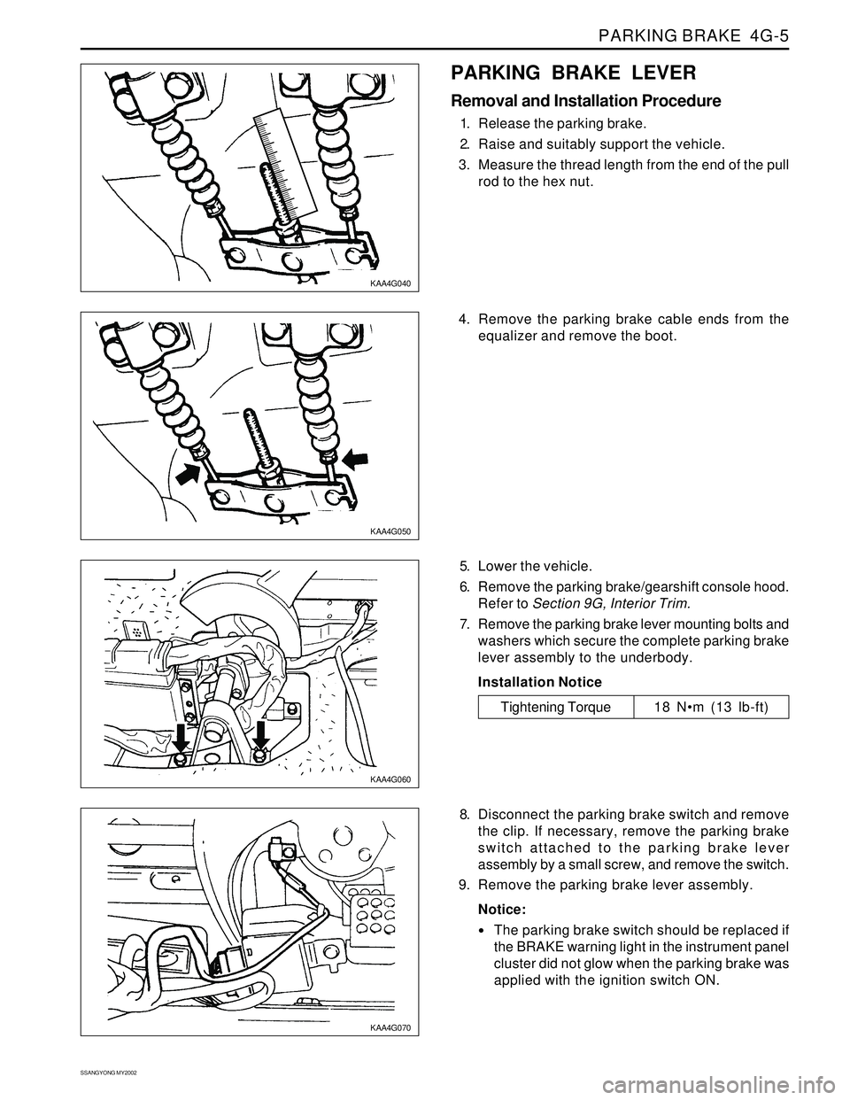
KAA4G040
KAA4G050
KAA4G060
KAA4G070
PARKING BRAKE LEVER
Removal and Installation Procedure
1. Release the parking brake.
2. Raise and suitably support the vehicle.
3. Measure the thread length from the end of the pull
rod to the hex nut.
5. Lower the vehicle.
6. Remove the parking brake/gearshift console hood.
Refer to Section 9G, Interior Trim.
7. Remove the parking brake lever mounting bolts and
washers which secure the complete parking brake
lever assembly to the underbody.
Installation Notice
8. Disconnect the parking brake switch and remove
the clip. If necessary, remove the parking brake
switch attached to the parking brake lever
assembly by a small screw, and remove the switch.
9. Remove the parking brake lever assembly.
Notice:
The parking brake switch should be replaced if
the BRAKE warning light in the instrument panel
cluster did not glow when the parking brake was
applied with the ignition switch ON.
Tightening Torque 18 Nm (13 lb-ft) 4. Remove the parking brake cable ends from the
equalizer and remove the boot.
Page 1095 of 2053
SECTION 5A
AUTOMATIC TRANSMISSION
CAUTION: Disconnect the negative battery cable before removing or installing any electrical unit or when a
tool or equipment could easily come in contact with exposed electrical terminals. Disconnecting this cable
will help prevent personal injury and damage to the vehicle. The ignition must also be in LOCK unless
otherwise noted.
TABLE OF CONTENTS
Description and Operation . . . . . . . . . . . . . . . . . 5A-2
BTRA M74 4WD Automatic Transmission . . . . . . 5A-2
Operators Interfaces . . . . . . . . . . . . . . . . . . . . . 5A-2
Control Systems . . . . . . . . . . . . . . . . . . . . . . . . 5A-3
Electronic Control System . . . . . . . . . . . . . . . . . 5A-3
Hydraulic Control System . . . . . . . . . . . . . . . . . . 5A-9
Hydraulic Control Circuit . . . . . . . . . . . . . . . . . . 5A-10
Power Train System . . . . . . . . . . . . . . . . . . . . . 5A-14
Power Flows . . . . . . . . . . . . . . . . . . . . . . . . . . 5A-18
Park and Neutral . . . . . . . . . . . . . . . . . . . . . . . 5A-20
Reverse . . . . . . . . . . . . . . . . . . . . . . . . . . . . . . 5A-22
Manual 1 . . . . . . . . . . . . . . . . . . . . . . . . . . . . . 5A-24
Drive 1 . . . . . . . . . . . . . . . . . . . . . . . . . . . . . . 5A-26
Drive 2 and Manual 2 . . . . . . . . . . . . . . . . . . . . 5A-28
Drive 3 and Manual 3 . . . . . . . . . . . . . . . . . . . . 5A-30
Drive 3 Lock Up and Manual 3 Lock Up . . . . . . 5A-32
Drive 4 (Overdrive) . . . . . . . . . . . . . . . . . . . . . 5A-34
Drive 4 Lock Up . . . . . . . . . . . . . . . . . . . . . . . . 5A-36
Diagnostic Information and Procedures . . . . . 5A-38
Diagnosis . . . . . . . . . . . . . . . . . . . . . . . . . . . . . 5A-38
Basic Knowledge Required . . . . . . . . . . . . . . . 5A-38
Functional Check Procedure . . . . . . . . . . . . . . . 5A-38
Transmission Fluid Level Service Procedure . . . 5A-38
Fluid Leak Diagnosis and Repair . . . . . . . . . . . 5A-39
Electrical / Garage Shift Test . . . . . . . . . . . . . . 5A-40
Road Test Procedure . . . . . . . . . . . . . . . . . . . . 5A-40
Electronic Adjustments . . . . . . . . . . . . . . . . . . 5A-40
Symptom Diagnosis . . . . . . . . . . . . . . . . . . . . . 5A-41
Drive Faults . . . . . . . . . . . . . . . . . . . . . . . . . . . 5A-41
Faulty Shift Pattern . . . . . . . . . . . . . . . . . . . . . . 5A-42Shift Quality Faults . . . . . . . . . . . . . . . . . . . . . . 5A-44
After Teardown Faults . . . . . . . . . . . . . . . . . . . 5A-46
Trouble Code Diagnosis - Gasoline Vehicle . . 5A-48
TCM Diagnostic System Overview . . . . . . . . . . 5A-48
Clearing Trouble Codes . . . . . . . . . . . . . . . . . . 5A-48
Diagnostic Trouble Codes . . . . . . . . . . . . . . . . 5A-48
Trouble Code Diagnosis - Diesel Vehicle . . . . . 5A-50
TCM Diagnostic System Overview . . . . . . . . . . 5A-50
Clearing Trouble Codes . . . . . . . . . . . . . . . . . . 5A-50
Diagnostic Trouble Codes . . . . . . . . . . . . . . . . 5A-50
Repair Instructions . . . . . . . . . . . . . . . . . . . . . . 5A-157
On-Vehicle Service . . . . . . . . . . . . . . . . . . . . . . . 5A-157
Transmission . . . . . . . . . . . . . . . . . . . . . . . . . . 5A-157
Unit Repair . . . . . . . . . . . . . . . . . . . . . . . . . . . . 5A-160
Rebuild Warnings . . . . . . . . . . . . . . . . . . . . . . 5A-160
Disassembly Procedure . . . . . . . . . . . . . . . . . . 5A-161
Assembly Procedure . . . . . . . . . . . . . . . . . . . . 5A-171
Front and Rear Band Adjustment . . . . . . . . . . . 5A-199
Gear Shift Control Lever . . . . . . . . . . . . . . . . . . 5A-202
Kickdown Switch . . . . . . . . . . . . . . . . . . . . . . . 5A-202
Specifications . . . . . . . . . . . . . . . . . . . . . . . . . . 5A-203
General Specification . . . . . . . . . . . . . . . . . . . . 5A-203
Fastener Tightening Specifications . . . . . . . . . . 5A-205
Schematic and Routing Diagrams . . . . . . . . . . 5A-206
TCM Wiring Diagrams (Gasoline Engine) . . . . . 5A-206
TCM Wiring Diagrams (Diesel Engine) . . . . . . . 5A-208
Connector End View . . . . . . . . . . . . . . . . . . . . . 5A-210
Special Tools and Equipment . . . . . . . . . . . . . 5A-211
Special Tools Table . . . . . . . . . . . . . . . . . . . . . 5A-211
Page 1097 of 2053
AUTOMATIC TRANSMISSION 5A-3
SSANGYONG MY2002
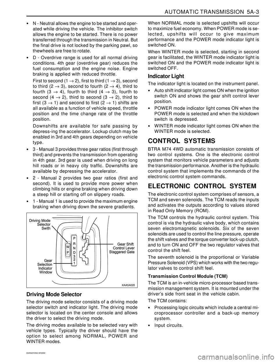
N - Neutral allows the engine to be started and oper-
ated while driving the vehicle. The inhibitor switch
allows the engine to be started. There is no power
transferred through the transmission in Neutral. But
the final drive is not locked by the parking pawl, so
thewheels are free to rotate.
D - Overdrive range is used for all normal driving
conditions. 4th gear (overdrive gear) reduces the
fuel consumption and the engine noise. Engine
braking is applied with reduced throttle.
First to second (1 → 2), first to third (1 → 3), second
to third (2 → 3), second to fourth (2 → 4), third to
fourth (3 → 4), fourth to third (4 → 3), fourth to
second (4 → 2), third to second (3 → 2), third to
first (3 → 1) and second to first (2 → 1) shifts are
all available as a function of vehicle speed, throttle
position and the time change rate of the throttle
position.
Downshifts are available for safe passing by
depress-ing the accelerator. Lockup clutch may be
enabled in 3rd and 4th gears depending on vehicle
type.
3 - Manual 3 provides three gear ratios (first through
third) and prevents the transmission from operating
in 4th gear. 3rd gear is used when driving on long
hill roads or in heavy city traffic. Downshifts are
available by depressing the accelerator.
2 - Manual 2 provides two gear ratios (first and
second). It is used to provide more power when
climbing hills or engine braking when driving down
a steep hill or starting off on slippery roads.
1 - Manual 1 is used to provide the maximum engine
braking when driving down the severe gradients.When NORMAL mode is selected upshifts will occur
to maximize fuel economy. When POWER mode is se-
lected, upshifts will occur to give maximum
performance and the POWER mode indicator light is
switched ON.
When WINTER mode is selected, starting in second
gear is facilitated, the WINTER mode indicator light is
switched ON and the POWER mode indicator light is
switched OFF.
Indicator Light
The indicator light is located on the instrument panel.
Auto shift indicator light comes ON when the ignition
switch ON and shows the gear shift control lever
position.
POWER mode indicator light comes ON when the
POWER mode is selected and when the kickdown
switch is depressed.
WINTER mode indicator light comes ON when the
WINTER mode is selected.
CONTROL SYSTEMS
BTRA M74 4WD automatic transmission consists of
two control systems. One is the electronic control
system that monitors vehicle parameters and adjusts
the transmission performance. Another is the hydraulic
control system that implements the commands of the
electronic control system commands.
ELECTRONIC CONTROL SYSTEM
The electronic control system comprises of sensors, a
TCM and seven solenoids. The TCM reads the inputs
and activates the outputs according to values stored
in Read Only Memory (ROM).
The TCM controls the hydraulic control system. This
control is via the hydraulic valve body, which contains
seven electromagnetic solenoids. Six of the seven
solenoids are used to control the line pressure, operate
the shift valves and the torque converter lock-up clutch,
and to turn ON and OFF the two regulator valves that
control the shift feel.
The seventh solenoid is the proportional or Variable
Pressure Solenoid (VPS) which works with the two regu-
lator valves to control shift feel.
Transmission Control Module (TCM)
The TCM is an in-vehicle micro-processor based trans-
mission management system. It is mounted under the
driver’s side front seat in the vehicle cabin.
The TCM contains:
Processing logic circuits which include a central mi-
croprocessor controller and a back-up memory
system.
Input circuits.
Driving Mode Selector
The driving mode selector consists of a driving mode
selector switch and indicator light. The driving mode
selector is located on the center console and allows
the driver to select the driving mode.
The driving modes available to be selected vary with
vehicle types. Typically the driver should have the
option to select among NORMAL, POWER and
WINTER modes.
KAA5A020
Page 1143 of 2053
5A-48 AUTOMATIC TRANSMISSION
SSANGYONG MY2002
TROUBLE CODE DIAGNOSIS - GASOLINE VEHICLE
TCM DIAGNOSTIC SYSTEM
OVERVIEW
Notice: To prevent Transmission Control Module (TCM)
damage. The ignition key must be OFF when
disconnection or reconnection the power to the TCM
(for example bttery cable, TCM pigtail connector, TCM
fuse, jumper cables, etc.).
When the TCM detects a system fault, a Diagnostic
Trouble Code (DTC) is set in the TCM. This code is
present while the fault conditions are met and is stored
as a ‘History DTC’ until cleared. Condition for setting
and clearing each TCM DTC are provided in the relevant
sections.
In the case where the vehicle type is certified for Eure
On-Board Diagnostic (EOBD) compliance, the Engine
Control Module (ECM) provides the communication linkto the EOBD scan tool to pass on any EOBD relevant
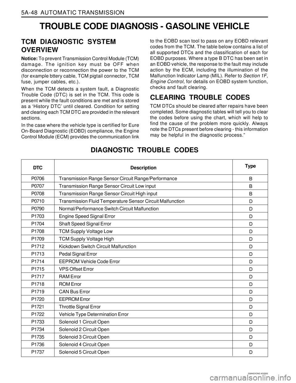
codes from the TCM. The table below contains a list of
all supported DTCs and the classification of each for
EOBD purposes. Where a type B DTC has been set in
an EOBD vehicle, the response to the fault may include
action by the ECM, including the illumination of the
Malfunction lndicator Lamp (MIL). Refer to Section 1F,
Engine Control, for details on EOBD system function,
checks and fault clearing.
CLEARING TROUBLE CODES
TCM DTCs should be cleared after repairs have been
completed. Some diagnostic tables will tell you to clear
the codes before using the chart, which will help to
find the cause of the problem more quickly. Always
note the DTCs present before clearing - this information
may be helpful in the diagnostic process.”
DIAGNOSTIC TROUBLE CODES
DTC
P0706
P0707
P0708
P0710
P0790
P1703
P1704
P1708
P1709
P1712
P1713
P1714
P1715
P1717
P1718
P1719
P1720
P1721
P1722
P1733
P1734
P1735
P1736
P1737Type
B
B
B
D
D
D
D
D
D
D
D
D
D
D
D
D
D
D
D
D
D
D
D
D Description
Transmission Range Sensor Circuit Range/Performance
Transmission Range Sensor Circuit Low input
Transmission Range Sensor Circuit High input
Transmission Fluid Temperature Sensor Circuit Malfunction
Normal/Performance Switch Circuit Malfunction
Engine Speed Signal Error
Shaft Speed Signal Error
TCM Supply Voltage Low
TCM Supply Voltage High
Kickdown Switch Circuit Malfunction
Pedal Signal Error
EEPROM Vehicle Code Error
VPS Offset Error
RAM Error
ROM Error
CAN Bus Error
EEPROM Error
Throttle Signal Error
Vehicle Type Determination Error
Solenoid 1 Circuit Open
Solenoid 2 Circuit Open
Solenoid 3 Circuit Open
Solenoid 4 Circuit Open
Solenoid 5 Circuit Open
Page 1145 of 2053
5A-50 AUTOMATIC TRANSMISSION
SSANGYONG MY2002
Transmission Range Sensor Circuit Low Input
Transmission Range Sensor Circuit High Input
Transmission Fluid Temperature Sensor Circuit Malfunction
Normal/Performance Switch Circuit Malfunction
Engine Speed Signal Error
Shaft Speed Signal Error
TCM Supply Voltage Low
TCM Supply Voltage High
Air Conditioning Switch Circuit Malfunction
Kickdown Switch Circuit Malfunction
EEPROM Vehicle Code Error
VPS Offset Error
Throttle Not Learnt Error
RAM Error
ROM Error
EEPROM Error
Throttle Signal Error
Vehicle Type Determination Error
Solenoid 1 Circuit Open
Solenoid 2 Circuit Open
Solenoid 3 Circuit Open
Solenoid 4 Circuit Open
Solenoid 5 Circuit Open
Solenoid 6 Circuit Open
Solenoid 7 Circuit Open
Solenoid 1 Circuit Short
Solenoid 2 Circuit Short
Solenoid 3 Circuit Short
Solenoid 4 Circuit Short
TROUBLE CODE DIAGNOSIS - DIESEL VEHICLE
TCM DIAGNOSTIC SYSTEM
OVERVIEW
Notice: To prevent Transmission Control Module (TCM)
damage. The ignition key must be OFF when
disconnection or reconnection the power to the TCM
(for example bttery cable, TCM pigtail connector, TCM
fuse, jumper cables, etc.).
When the TCM detects a system fault, a Diagnostic
Trouble Code (DTC) is set in the TCM. This code is
present while the fault conditions are met and is storedas a ‘History DTC’ until cleared. Condition for setting
and clearing each TCM DTC are provided in the relevant
sections.CLEARING TROUBLE CODES
TCM DTCs should be cleared after repairs have been
completed. Some diagnostic tables will tell you to clear
the codes before using the chart, which will help to
find the cause of the problem more quickly. Always
note the DTCs present before clearing - this information
may be helpful in the diagnostic process.
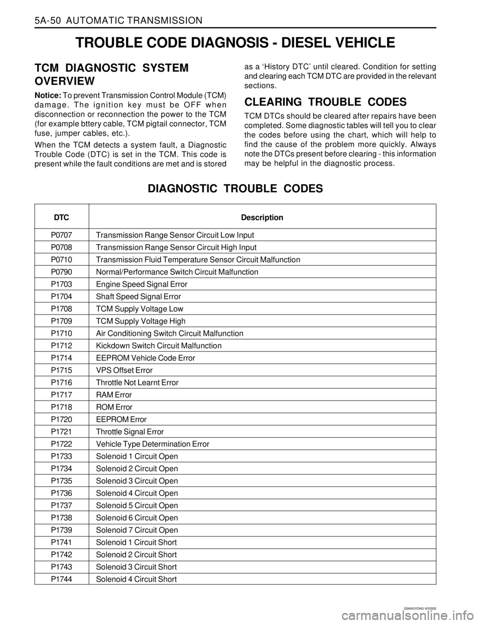
DIAGNOSTIC TROUBLE CODES
DTC
P0707
P0708
P0710
P0790
P1703
P1704
P1708
P1709
P1710
P1712
P1714
P1715
P1716
P1717
P1718
P1720
P1721
P1722
P1733
P1734
P1735
P1736
P1737
P1738
P1739
P1741
P1742
P1743
P1744Description
Page 1162 of 2053
AUTOMATIC TRANSMISSION 5A-67
SSANGYONG MY2002
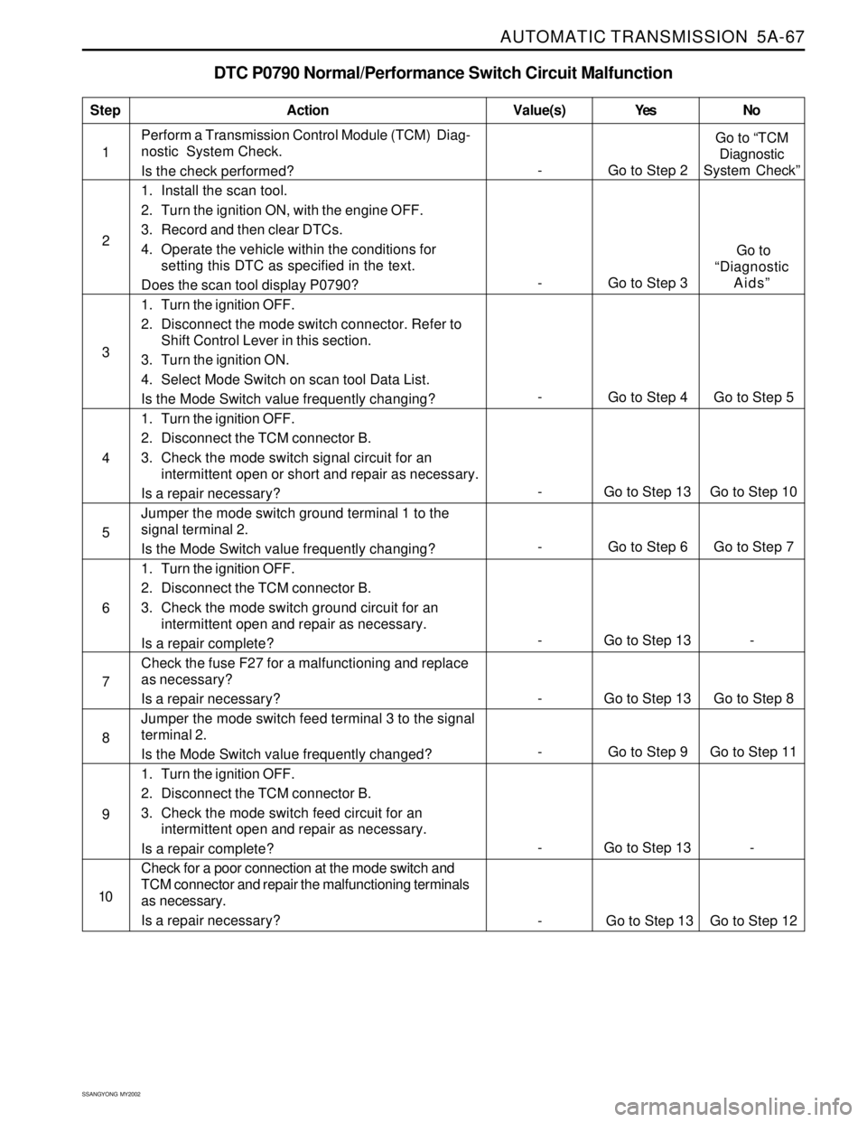
DTC P0790 Normal/Performance Switch Circuit Malfunction
1Perform a Transmission Control Module (TCM) Diag-
nostic System Check.
Is the check performed?
1. Install the scan tool.
2. Turn the ignition ON, with the engine OFF.
3. Record and then clear DTCs.
4. Operate the vehicle within the conditions for
setting this DTC as specified in the text.
Does the scan tool display P0790?
1. Turn the ignition OFF.
2. Disconnect the mode switch connector. Refer to
Shift Control Lever in this section.
3. Turn the ignition ON.
4. Select Mode Switch on scan tool Data List.
Is the Mode Switch value frequently changing?
1. Turn the ignition OFF.
2. Disconnect the TCM connector B.
3. Check the mode switch signal circuit for an
intermittent open or short and repair as necessary.
Is a repair necessary?
Jumper the mode switch ground terminal 1 to the
signal terminal 2.
Is the Mode Switch value frequently changing?
1. Turn the ignition OFF.
2. Disconnect the TCM connector B.
3. Check the mode switch ground circuit for an
intermittent open and repair as necessary.
Is a repair complete?
Check the fuse F27 for a malfunctioning and replace
as necessary?
Is a repair necessary?
Jumper the mode switch feed terminal 3 to the signal
terminal 2.
Is the Mode Switch value frequently changed?
1. Turn the ignition OFF.
2. Disconnect the TCM connector B.
3. Check the mode switch feed circuit for an
intermittent open and repair as necessary.
Is a repair complete?
Check for a poor connection at the mode switch and
TCM connector and repair the malfunctioning terminals
as necessary.
Is a repair necessary?
StepAction Value(s) Yes No
2
3
- Go to Step 6 Go to Step 7 5
- Go to Step 13 - 6
- Go to Step 13 Go to Step 10 4
- Go to Step 13 Go to Step 8 7
- Go to Step 9 Go to Step 11 8
- Go to Step 13 - 9
10
- Go to Step 2Go to “TCM
Diagnostic
System Check”
-
Go to Step 4 Go to Step 5
- Go to Step 3 Go to
“Diagnostic
Aids”
- Go to Step 13 Go to Step 12