1997 MERCEDES-BENZ ML500 roof
[x] Cancel search: roofPage 1578 of 4133
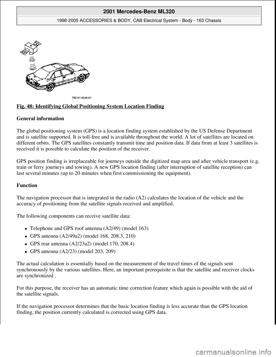
Fig. 48: Identifying Global Positioning System Location Finding
General information
The global positioning system (GPS) is a location finding system established by the US Defense Department
and is satellite supported. It is toll-free and is available throughout the world. A lot of satellites are located on
different orbits. The GPS satellites constantly transmit time and position data. If data from at least 3 satellites is
received it is possible to calculate the position of the receiver.
GPS position finding is irreplaceable for journeys outside the digitized map area and after vehicle transport (e.g.
train or ferry journeys and towing). A new GPS location finding (after interruption of satellite reception) can
last several minutes (up to 20 minutes when first commissioning the equipment).
Function
The navigation processor that is integrated in the radio (A2) calculates the location of the vehicle and the
accuracy of positioning from the satellite signals received and amplified.
The following components can receive satellite data:
Telephone and GPS roof antenna (A2/49) (model 163)
GPS antenna (A2/49a2) (model 168, 208.3, 210)
GPS rear antenna (A2/23a2) (model 170, 208.4)
GPS antenna (A2/23) (model 203, 209)
The actual calculation is essentially based on the measurement of the travel times of the signals sent
synchronously by the various satellites. Here, an important prerequisite is that the satellite and receiver clocks
are synchronized .
For this purpose, the receiver has an automatic time correction feature which again is possible with the aid of
the satellite signals.
If the navigation processor determines that the basic location finding is less accurate than the GPS location
findin
g, the position currently calculated is corrected using GPS data.
2001 Mercedes-Benz ML320
1998-2005 ACCESSORIES & BODY, CAB Electrical System - Body - 163 Chassis
me
Saturday, October 02, 2010 3:30:05 PMPage 83 © 2006 Mitchell Repair Information Company, LLC.
Page 1579 of 4133
In addition, the vehicle's course of travel is determined with the aid of the sequence of the locations calculated
with GPS.
Possible interference when receiving GPS signals
Since GPS operates in the GHz range (microwaves) and the signals are weak, reception interference can occur
as the result of:
atmospheric interference, e.g. weather, water vapor, fog
multiple reception resulting from reflecting of signals, e.g. from building walls
Signal shadows, e.g., in built-up areas, tunnel, in the proximity of higher buildings and trees
GPS reception therefore necessitates a clear view of the sky. The location finding accuracy of the GPS system is
100 m or better.
GLOBAL POSITIONING SYSTEM LOCATION FINDING, FUNCTION - GF82.61-P-3007GI
MODEL 163 as of 1.9.01 with CODE (522) Modular control system (MCS) radio USA with CODE (357)
Navigation system - additional unit with CODE (818b) Single CD player - additional unit with CODE
(491) U.S. version
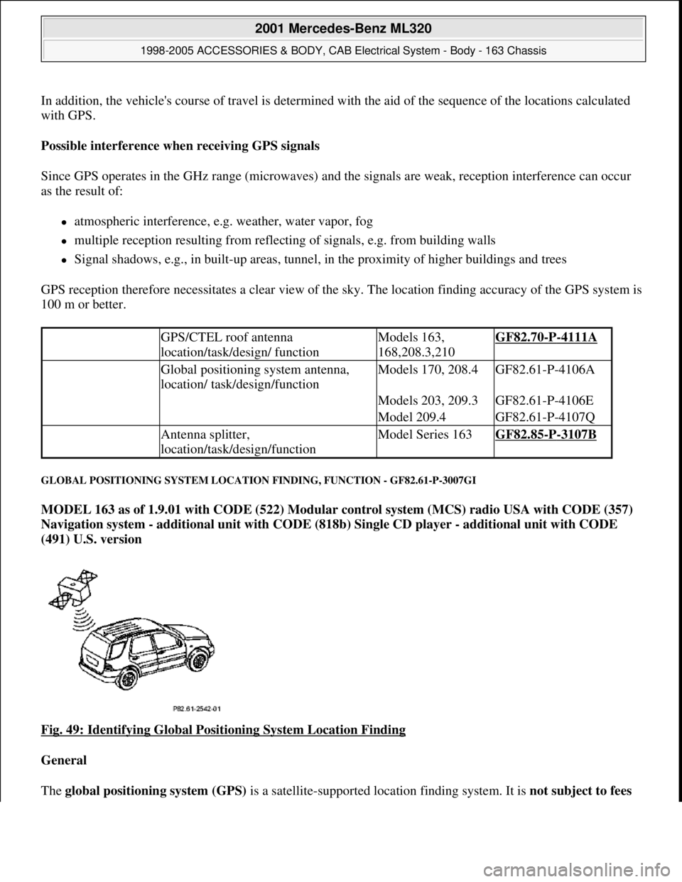
Fig. 49: Identifying Global Positioning System Location Finding
General
The global positioning system (GPS) is a satellite-supported location findin
g system. It is not subject to fees
GPS/CTEL roof antenna
location/task/design/ functionModels 163,
168,208.3,210GF82.70-P-4111A
Global positioning system antenna,
location/ task/design/functionModels 170, 208.4GF82.61-P-4106A
Models 203, 209.3GF82.61-P-4106E
Model 209.4GF82.61-P-4107Q
Antenna splitter,
location/task/design/functionModel Series 163GF82.85-P-3107B
2001 Mercedes-Benz ML320
1998-2005 ACCESSORIES & BODY, CAB Electrical System - Body - 163 Chassis
me
Saturday, October 02, 2010 3:30:05 PMPage 84 © 2006 Mitchell Repair Information Company, LLC.
Page 1580 of 4133
and is available worldwide . Presently there are 266 satellites on 6 different earth orbits. The GPSsatellites
permanently transmit time and position data. If data from a minimum of 3 satellites is received (with two-
dimensional location finding) it is possible to calculate the position of the receiver.
The GPS location finding is particularly important when driving outside of the digitized map area and
following vehicle transport (e.g. train, ferry or towing).
A repeated GPS location finding (following satellite reception interruption) can take several minutes (when
unit is initially started up to 20 min .).
GPS map matching function
The navigation processor calculates the location of the vehicle and the accuracy of positioning from the
satellite signals received and amplified by the GPS antenna (A2/49) . The current calculation is based
primarily on the measurement of the transmission times for the signals transmitted synchronously by the
various satellites. Here, an important prerequisite is that the satellite and receiver clocks are synchronized . For
this purpose, the receiver has an automatic time correction feature which again is possible with the aid of the
satellite signals. If the navigation processor determines that the basic location finding is less precise than the
GPS location finding, the currently calculated position is corrected with the aid of the GPS data .
Moreover, the vehicle route is determined from the location sequence calculated with GPS .
Approx. 50 new GPS location finding calculations are performed each minute.
Possible interference when receiving GPS signals
Since GPS operates in the GHz (microwave) range and the signals are weak, reception interferences can
occur from
atmospheric interferences, e.g. weather, water vapor, fog,
multiple path reception due to signal reflections, e.g. from building walls
Signal shadows, e.g. in built-up areas, tunnels, high buildings, trees
A free view of the sky is therefore necessary for GPS reception The location finding accuracy is approx. 100
m or better .
Basic location finding,
function GF82.61-P-3006GI
Map-supported location
finding, function GF82.61-P-3008GI
Guidance, function GF82.61-P-3012GI
Radio and navigation
module, location/purpose/
design/function GF82.61-P-4109GI
GPS roof antenna/telephone, GF82.70-P-4111A
2001 Mercedes-Benz ML320
1998-2005 ACCESSORIES & BODY, CAB Electrical System - Body - 163 Chassis
me
Saturday, October 02, 2010 3:30:05 PMPage 85 © 2006 Mitchell Repair Information Company, LLC.
Page 1596 of 4133
The display of the radios (A2) has 197 x 32 pixels. Texts are displayed in 3 lines.
After particular functions are called (e.g. navigation), the bottom line shows a variable inscription for the row of
buttons underneath (multifunction buttons). As a result the system can be operated very conveniently with a few
buttons, as the function which is activated when the button is operated, is shown in plain text (e.g. LANG,
ITEM, DYN, CLOCK etc.).
Audio signal output
The audio signals of the various sources (CD, voice output for navigation etc.) are processed by the radio (A2)
and amplified before output by the vehicle speakers.
On models 168, 170, 208 and 210 with the sound system (code 810) the audio signals are finally amplified
by the amplifier for the sound system (N40/3). For this, the audio source data (low-frequency signals) are
transmitted to the amplifier for the sound system (N40/3) via separate lines.
On models 163 and 209 the final amplification of the audio signal is performed by the sound amplifier
(A2/13). All the data are transmitted via the D2B.
Audio mute
An incoming phone call activates the audio mute function (a separate signal input exists on the radio (A2) for
this). When the audio mute function is activated, the current audio source (e.g. radio) is muted automatically.
Navigation processor, GPS control module and gyrosensor
The navigation processor is the central component of the navigation system.
It is integrated into the radio (A2) and from the incoming signals continuously calculates the location and once
the destination is entered calculates the route for navigation. The GPS receiver is integrated into the navigation
processor. It evaluates the satellite signals and calculates from them the vehicle position in degrees longitude
and latitude. Various GPS antennae are used to receive these signals depending on the vehicle model:
Model 163: telephone and GPS roof antenna (A2/49)
Models 168, 208.3, 210: GPS antenna (A2/49a2)
Models 170, 208.4: GPS rear antenna (A2/23a2)
Model 209: GPS antenna (A2/23)
Reception from at least 3 satellites is necessary for exact GPS position calculation. A free view of the sky is
required for this purpose.
The integrated gyrosensor continuously senses every change in direction of the vehicle. Evaluation of this data
is accomplished by the navigation processor.
Calibration of the gyrosensor is not required.
2001 Mercedes-Benz ML320
1998-2005 ACCESSORIES & BODY, CAB Electrical System - Body - 163 Chassis
me
Saturday, October 02, 2010 3:30:05 PMPage 101 © 2006 Mitchell Repair Information Company, LLC.
Page 1598 of 4133
as a synchronization signal. The electronic control in the display unit evaluates the RGB signaland actuates the
individual pixels line by line according to color and intensity.
A horizontal synchronization pulse is output at the end of each line. The electronic circuitry of the display unit
then starts the next line. After reaching the last line on the display, a vertical synchronization pulse is output and
the electronic circuitry starts again with the first line.
Audio signal output
The audio signals from the various sources (CD, voice output for route guidance, ...) are processed by the radio
and navigation module (A2/ 56) and amplified before output over the vehicle loudspeakers . On vehicles
with sound system (code 810) final amplification of the audio signals is accomplished by the sound amplifier
(A2/13) . For this purpose audio source data is transmitted to the sound amplifier (A2/13) via the digital data
bus ( D2B ).
Diagnosis interface (K bus) and D2B component error management
During the radio and navigation module (A2/56) mode the system stores all errors which occur in the non-
volatile memory. These errors can then be read out on the diagnostic interface (K bus) with Star diagnosis .
Output of the errors on the display unit is not possible.
Error management also includes components connected to the digital data bus ( D2B ).
Each D2B component has its own DTC memory . The errors are transmitted to the radio and navigation
module (A2/56) via the digital data bus (D2B) on request by STAR diagnosis and can then be read out with the
diagnostic interface.
Navigation processor and GPS control module
The navigation processor is the central component of the radio and navigation module (A2/56) . It is
integrated into the radio and navigation module (A2/56)and calculates the location and vehicle route from the
incoming signals after entering the route.
The GPS control module is a part of the navigation processor. It evaluates the satellite signals distributed by
the CTEL/GPS roof antenna (A2/49) and the CTEL and GPS antenna splitter (A2/57) and calculates with
this information the vehicle position.
CD-ROM and CD drive
With the aid of the navigation CD drive it is possible to read data from the special navigation CD or play
audio CD's or play .
The following is stored on the navigation CD-ROM :
Program data for execution in navigation processor
Voice data for voice output
2001 Mercedes-Benz ML320
1998-2005 ACCESSORIES & BODY, CAB Electrical System - Body - 163 Chassis
me
Saturday, October 02, 2010 3:30:05 PMPage 103 © 2006 Mitchell Repair Information Company, LLC.
Page 1601 of 4133
SURVEY OF SYSTEM COMPONENTS, AUDIO 30 APS, LOCATION/TASK/ DESIGN/FUNCTION - GF82.61-P-9998ZZ
MODELS 163, 168, 170, 203.0 /2 /7, 208, 209.3 /4, 210 with CODE (353) Audio 30 APS
CD changer
(optional)
Sound system
(optional)
Navigation system
(optional)
Telephone (optional)
Radio and navigation
module, design GF82.61-P-4109-03GI
Radio and navigation
module, function GF82.61-P-4109-04GI
Radio and navigation unit,
location/task/design/ functionModel 163, 168,
170,208,210GF82.61-P-4109A
Model 209GF82.61-P-4109QA
Radio location/task/design/functionModel 203GF82.60-P-4109P
Additional fan for radio/navigation
unit, location/ taskModel 203 as of
1.6.03GF82.61-P-4110P
FM/AM antenna amplifier,
location/task/design/ functionModels 163, 168,
170, 208.4, 210.2GF82.62-P-4101A
Models 208.3, 210
(except, 210.2) with
code 352a
Antenna amplifier module,
location/task/design/ functionModels 203.0/7,
209.3GF82.62-P-3105PP
Model 203.2GF82.62-P-3105PS
Model 209.4GF82.62-P-3105QA
Rear window antenna,
location/task/design/ functionModels 203.0/7,
209.3GF82.62-P-3106PP
Model 203.2GF82.62-P-3106PS
Windshield antenna,
location/task/design/ functionModel 209.4GF82.62-P-3112Q
Radio reception antenna, location/taskModel 209.4GF82.62-P-4103Q
Radio reception amplifier, location/taskModel 209.4GF82.62-P-4104Q
Telephone antenna, location/taskModels 203.0/2/7,
209.3GF82.62-P-4105PP
Model 209.4GF82.62-P-4105Q
GPS/telephone roof antenna,
location/task/ design/functionModels 163, 168,
208.3, 210GF82.70-P-4111A
2001 Mercedes-Benz ML320
1998-2005 ACCESSORIES & BODY, CAB Electrical System - Body - 163 Chassis
me
Saturday, October 02, 2010 3:30:05 PMPage 106 © 2006 Mitchell Repair Information Company, LLC.
Page 1606 of 4133
A further distinction in terms of the antennas is that certain antennas are used only for receptionwhile others
are used both for reception as well as for transmission .
Function up to 31.08.01
The CTEL and GPS roof antenna (A2/49 ) is supplied with direct voltage via the antenna cable ( phantom
feed ).
It is connected by a coaxial cable to the CTEL and GPS antenna splitter (A2/57) . These two components
ensure reception and transmission of the GSM signals and reception of the GSP signals .
Function as of 01.09.01
The CTEL and GPS roof antenna (A2/49) has the antenna splitter and an antenna amplifier integrated, which
eliminates the need for the CTEL and GPS antenna splitter (A2/57) .
The detailed descriptions of the individual systems and components are given in the reference documents
listed below.
SPEAKER SYSTEM (LSA) ARRANGEMENT OF COMPONENTS - GF82.62-P-0002-01D
Model 163
Cockpit management and data system
(COMAND) function GF82.85-P-
0003GH
Modular control system (MCS), function GF82.85-P-0011GI
Rear window antenna,
location/purpose/design/ function GF82.62-P-
3106GH
FM/AM antenna amplifier,
location/purpose/ design/function GF82.62-P-4101A
GPS/CTEL roof antenna,
location/purpose/ design/function GF82.70-P-4111A
Antenna, location/purpose/design/functionValid up to
31.08.01GF82.85-P-
3107GH
2001 Mercedes-Benz ML320
1998-2005 ACCESSORIES & BODY, CAB Electrical System - Body - 163 Chassis
me
Saturday, October 02, 2010 3:30:05 PMPage 111 © 2006 Mitchell Repair Information Company, LLC.
Page 1615 of 4133
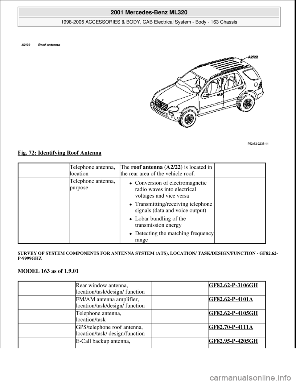
Fig. 72: Identifying Roof Antenna
SURVEY OF SYSTEM COMPONENTS FOR ANTENNA SYSTEM (ATS), LOCATION/ TASK/DESIGN/FUNCTION - GF82.62-
P-9999GHZ
MODEL 163 as of 1.9.01
Telephone antenna,
locationThe roof antenna (A2/22) is located in
the rear area of the vehicle roof.
Telephone antenna,
purposeConversion of electromagnetic
radio waves into electrical
voltages and vice versa
Transmitting/receiving telephone
signals (data and voice output)
Lobar bundling of the
transmission energy
Detecting the matching frequency
range
Rear window antenna,
location/task/design/ function GF82.62-P-3106GH
FM/AM antenna amplifier,
location/task/design/ function GF82.62-P-4101A
Telephone antenna,
location/task GF82.62-P-4105GH
GPS/telephone roof antenna,
location/task/ design/function GF82.70-P-4111A
E-Call backup antenna, GF82.95-P-4205GH
2001 Mercedes-Benz ML320
1998-2005 ACCESSORIES & BODY, CAB Electrical System - Body - 163 Chassis
me
Saturday, October 02, 2010 3:30:06 PMPage 120 © 2006 Mitchell Repair Information Company, LLC.