1997 MERCEDES-BENZ ML500 roof
[x] Cancel search: roofPage 743 of 4133
276
Roof rack
Te ch n ica l
data
Instruments
and controls Operation Driving
Instrument
cluster display Practical hints
Car care Index
Roof rack
Use only those roof racks approved by Mercedes-Benz.
Follow manufacturer’s installation instructions. They
mount to the roof rails and do not require additional
supports (e.g. suction cups or legs). Such supports may
lead to marring of the paint or denting the roof. For
further information inquire at your Mercedes-Benz
Light Truck Center.
Take into consideration that when the roof rack is
loaded, the handling characteristics are different from
those when operating the vehicles without the roof rack
loaded.
Page 745 of 4133
278
Cleaning and care of the vehicle
Te ch n ica l
data
Instruments
and controls Operation Driving
Instrument
cluster display Practical hints
Car care Index
Cleaning and care of the vehicle
In operation, your vehicle is subjected to varying
external inf luences which, if gone unchecked, can
attack the paintwork as well as the underbody and
cause lasting damage.
Such damage is caused not only by extreme and varying
climatic conditions, but also by air polution, road salt,
tar, gravel and stone chipping. Grease and oil, fuel,
coolant, brake fluid, bird droppings, insects, tree resins
etc. should be removed immediately to avoid paint
damage. Frequent washing reduces and / or eliminates
the aggressiveness and potency of the above adverse
influences. More frequent washings are necessary to deal with
unfavorable conditions; for example, near the ocean, in
industrial areas (smoke, exhaust emissions), or during
winter operation.
You should check your vehicle from time to time for
stone chipping or other damage. Any damage should be
repaired as soon as possible to prevent the start of
corrosion.
In doing so, do not neglect the underside of the vehicle.
A prerequisite for a thorough check is a washing of the
underbody followed by a thorough inspection. Damaged
areas need to be reundercoated.
Your vehicle has been treated at the factory with a wax-
base ru stproof ing in th e body cavities w hich will la st for
the lifetime of the vehicle. Post-production treatment is
neither necessary nor recommended by Mercedes-Benz
because of the possibility of incompatibility between
materials used in the production process and others
applied later.
We have selected car-care products and compiled
recommendations which are specially matched to our
vehicles and which always reflect the latest technology.
You can obtain Mercedes-Benz approved car-care
products at your authorized Mercedes-Benz Light Truck
Center.
Wa r n i n g !
Many cleaning products can be hazardous. Some
are poisonous, others are flammable. Always follow
the instructions on the particular container.
Always open your vehicle’s doors or windows when
cleaning the inside.Never use fluids or solvents that are not designed
for cleaning your vehicle.
Page 757 of 4133
290
Technical data
Te ch n ica l
data
Instruments
and controls Operation Driving
Instrument
cluster display Practical hints Car care Index
Electrical system
We i g h t s
(see certification tag)
Model ML 320 ML 430 ML 55 AMG
Generator (alternator) 14 V / 115 A 14 V / 150 A 14 V / 150 A
S t a r te r m o to r 12 V / 1. 7 k W 12V / 1. 7 k W 12V / 1.7 k W
Battery 12V / 100 Ah 12V / 100 Ah 12V / 100 Ah
Spark plugs
Electrode gap
Tightening torque Bosch F 8 DPER
Beru 14 FGH 8 DPUR X 2
0.039 in (1.0 mm)
15–22ft.lb (20–30Nm) Bosch F 8 DPER
Beru 14 FGH 8 DPUR X 2
0.039 in (1.0 mm)
15–22ft.lb (20–30Nm) Bosch F 8 DPER
0.039 in (1.0 mm)
15–22ft.lb (20–30Nm)
Roof load max. 220 lbs (100 kg)
Page 773 of 4133
306
Index
Te ch n ica l
data
Instruments
and controls Operation Driving
Instrument
cluster display Practical hints Car care
Index
Parking lamp ...................................................... 90, 264
Replacing bulbs .........................................................260
Side marker lamp ......................................................264
Standing lamp .................................................... 90, 264
Taillamp assemblies .................................................265
Turn signal lamp ................................................ 90, 264
Turn signal lamp, side .............................................266
Layout of poly-V-belt ......................................................286
Liftgate ............................................................................... 34 Unlocking ..................................................................... 28
Lighter ..............................................................................119
Limp home mode (Automatic transmission) ............. 172
Loading instructions ..................................................... 136
Lockable storage compartment .....................................116
Locking and unlocking the vehicle ............................... 27
Low engine coolant level warning ..............................224
Low engine oil level warning .......................................224
LOW RANGE Indicator lamp ........................................................... 221
LOW RANGE mode ........................................................209 LOW RANGE – 4-ETS+ .............................................204
LOW RANGE – ABS ..................................................202
LOW RANGE – ESP ...................................................208
MMaintenance ...................................................................147
Malfunction and indicator lamps in the instrument cluster ......................................................................... 218
Manual locking/unlocking the doors ...........................29
Manual operation of Skyview Top .............................. 273
Manual operation of sliding/pop-up roof .................. 272
Manual seat, front ............................................................39
MCS, radio and telephone ............................................146
Mechanical keys ............................................................... 29
Memory .............................................................................42 Recalling ....................................................................... 42
Storing ........................................................................... 42
Mirror, exterior, adjusting ..............................................73
Mirror, exterior, rear view ..............................................73
Mirror, inside, rear view ................................................. 71
Mirrors, vanity ................................................................ 113
Page 775 of 4133
308
Index
Te ch n ica l
data
Instruments
and controls Operation Driving
Instrument
cluster display Practical hints Car care
Index
Remote control ................................................................. 24 Battery replacement .................................................270
Changing batteries ...................................................270
Operation ..................................................................... 26
Synchronizing remote control ................................ 271
Removable cargo floor plates ....................................... 129
Replacement keys ............................................................ 25
Replacing bulbs ..............................................................260
Replacing wiper blade insert .......................................275
Reporting safety defects ................................................. 16
Reserve key ................................................................ 24, 25
Roadside assistance ......................................................... 10
Roadside assistance call See Tele Aid ............................................................... 148
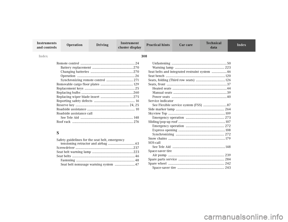
Roof rack ......................................................................... 276
SSafety guidelines for the seat belt, emergency tensioning retractor and airbag ................................ 63
Screwdriver .....................................................................237
Seat belt warning lamp .................................................223
Seat belts ........................................................................... 46 Fastening ...................................................................... 48
Seat belt nonusage warning system ........................ 47 Unfastening .................................................................. 50
Warning lamp ........................................................... 223
Seat belts and integrated restraint system .................. 46
Seat bench ....................................................................... 120
Seats, folding (Third row seats) ................................... 126
Seats, front ........................................................................37 Heated seats .................................................................44
Manual seats ................................................................39
Power seats .................................................................. 40
Service indicator
See Flexible service system (FSS) ............................ 87
Side marker lamp .......................................................... 264
Skyview Top ....................................................................109 Emergency operation .............................................. 273
Sliding/pop-up roof ........................................................107 Emergency operation .............................................. 272
Express opening ........................................................108
Synchronizing .......................................................... 272
Snow chains ....................................................................179
SOS-call See Tele Aid ...............................................................148
Space-saver tire
Air pump ................................................................... 239
Spare parts service ....................................................... 284
Spare wheel ................................................................... 242 Space-saver tire ........................................................ 243
Page 783 of 4133
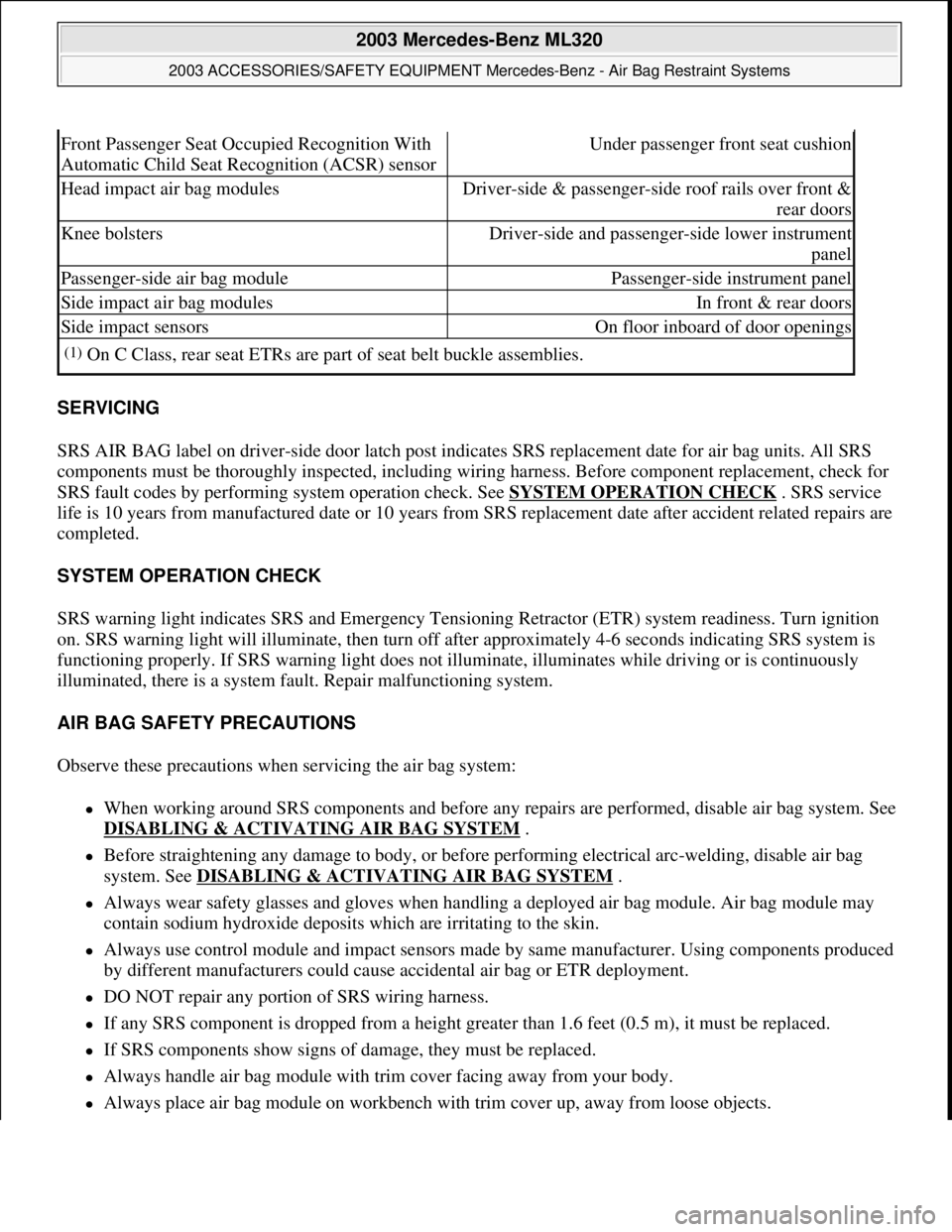
SERVICING
SRS AIR BAG label on driver-side door latch post indicates SRS replacement date for air bag units. All SRS
components must be thoroughly inspected, including wiring harness. Before component replacement, check for
SRS fault codes by performing system operation check. See SYSTEM OPERATION CHECK
. SRS service
life is 10 years from manufactured date or 10 years from SRS replacement date after accident related repairs are
completed.
SYSTEM OPERATION CHECK
SRS warning light indicates SRS and Emergency Tensioning Retractor (ETR) system readiness. Turn ignition
on. SRS warning light will illuminate, then turn off after approximately 4-6 seconds indicating SRS system is
functioning properly. If SRS warning light does not illuminate, illuminates while driving or is continuously
illuminated, there is a system fault. Repair malfunctioning system.
AIR BAG SAFETY PRECAUTIONS
Observe these precautions when servicing the air bag system:
When working around SRS components and before any repairs are performed, disable air bag system. See
DISABLING & ACTIVATING AIR BAG SYSTEM
.
Before straightening any damage to body, or before performing electrical arc-welding, disable air bag
system. See DISABLING & ACTIVATING AIR BAG SYSTEM
.
Always wear safety glasses and gloves when handling a deployed air bag module. Air bag module may
contain sodium hydroxide deposits which are irritating to the skin.
Always use control module and impact sensors made by same manufacturer. Using components produced
by different manufacturers could cause accidental air bag or ETR deployment.
DO NOT repair any portion of SRS wiring harness.
If any SRS component is dropped from a height greater than 1.6 feet (0.5 m), it must be replaced.
If SRS components show signs of damage, they must be replaced.
Always handle air bag module with trim cover facing away from your body.
Always place air bag module on workbench with trim cover up, away from loose objects.
Front Passenger Seat Occupied Recognition With
Automatic Child Seat Recognition (ACSR) sensorUnder passenger front seat cushion
Head impact air bag modulesDriver-side & passenger-side roof rails over front &
rear doors
Knee bolstersDriver-side and passenger-side lower instrument
panel
Passenger-side air bag modulePassenger-side instrument panel
Side impact air bag modulesIn front & rear doors
Side impact sensorsOn floor inboard of door openings
(1)On C Class, rear seat ETRs are part of seat belt buckle assemblies.
2003 Mercedes-Benz ML320
2003 ACCESSORIES/SAFETY EQUIPMENT Mercedes-Benz - Air Bag Restraint Systems
me
Saturday, October 02, 2010 3:32:07 PMPage 2 © 2006 Mitchell Repair Information Company, LLC.
Page 786 of 4133
2004 ACCESSORIES/SAF ETY EQUIPMENT
Mercedes-Benz - Air Bag Restraint Systems
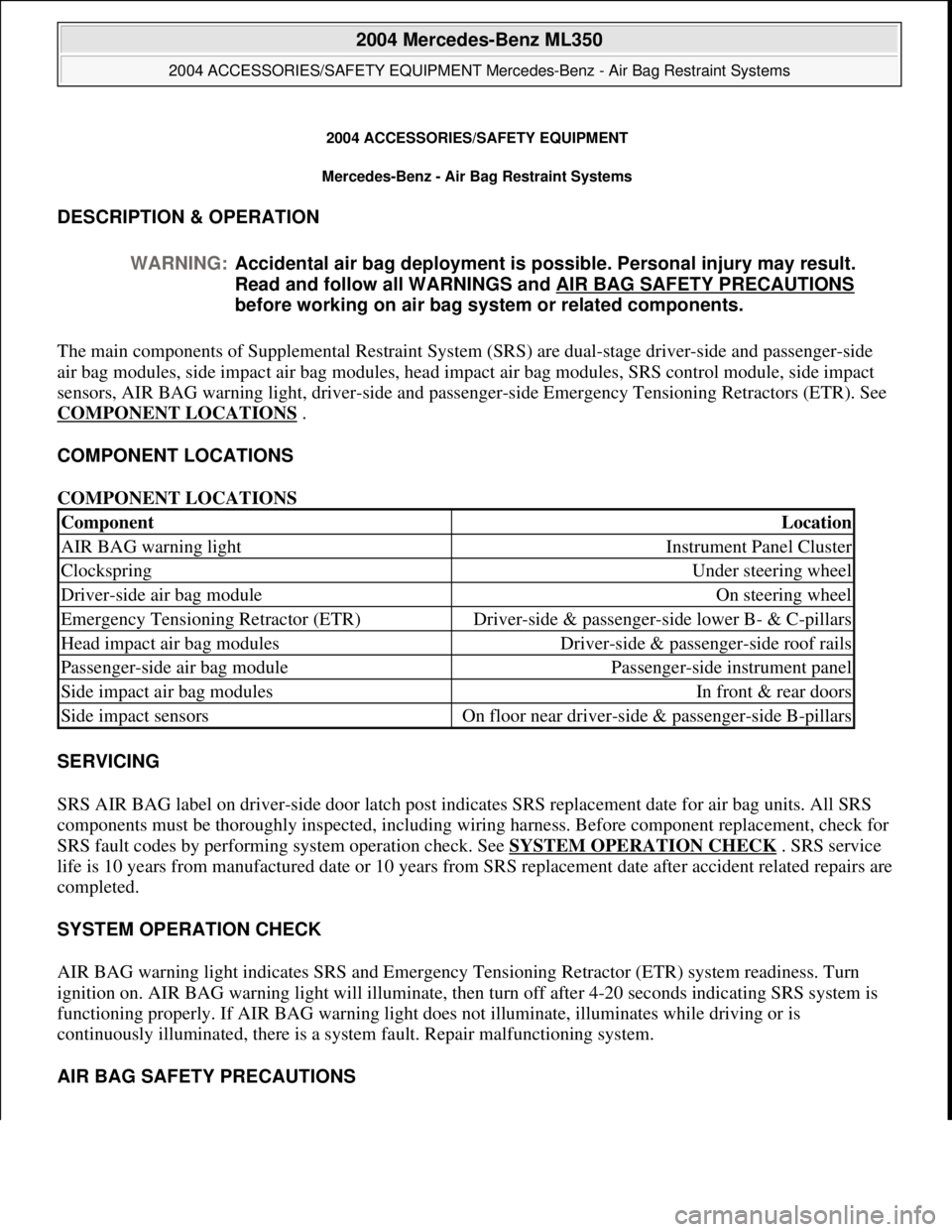
DESCRIPTION & OPERATION
The main components of Supplemental Restraint System (SRS) are dual-stage driver-side and passenger-side
air bag modules, side impact air bag modules, head impact air bag modules , SRS control module, side impact
sensors, AIR BAG warning light, driv er-side and passenger-side Emergency Tensioning Retractors (ETR). See
COMPONENT LOCATIONS
.
COMPONENT LOCATIONS
COMPONENT LOCATIONS
SERVICING
SRS AIR BAG label on driver-side door latch post indicates SRS replacement date for air bag units. All SRS
components must be thoroughly inspected, including wiring harness. Before component replacement, check for
SRS fault codes by performing system operation check. See SYSTEM OPERATION CHECK
. SRS service
life is 10 years from manufactured da te or 10 years from SRS replacement date after accident related repairs are
completed.
SYSTEM OPERATION CHECK
AIR BAG warning light indicates SRS and Emergency Te nsioning Retractor (ETR) system readiness. Turn
ignition on. AIR BAG warning light will illuminate, then turn off after 4-20 seconds indicating SRS system is
functioning properly. If AIR BAG warn ing light does not illuminate, illuminates while driving or is
continuously illuminated, ther e is a system fault. Repair malfunctioning system.
AIR BAG SAFETY PRECAUTIONS
WARNING:
Accidental air bag deployment is pos sible. Personal injury may result.
Read and follow all WARNINGS and AIR BAG SAFETY PRECAUTIONS
before working on ai r bag system or related components.
ComponentLocation
AIR BAG warning lightInstrument Panel Cluster
ClockspringUnder steering wheel
Driver-side air bag moduleOn steering wheel
Emergency Tensioning Retractor (ETR)Driver-side & passenger-si de lower B- & C-pillars
Head impact air bag modulesDriver-side & passenger-side roof rails
Passenger-side air bag modulePassenger-side instrument panel
Side impact air bag modulesIn front & rear doors
Side impact sensorsOn floor near driver-side & passenger-side B-pillars
2004 Mercedes-Benz ML350
2004 ACCESSORIES/SAFETY EQUIPMENT Merce des-Benz - Air Bag Restraint Systems
2004 Mercedes-Benz ML350
2004 ACCESSORIES/SAFETY EQUIPMENT Mercedes-Benz - Air Bag Restraint Systems
me
Saturday, October 02, 2010 3:40:40 PMPage 1 © 2006 Mitchell Repair Information Company, LLC.
me
Saturday, October 02, 2010 3:40:43 PMPage 1 © 2006 Mitchell Repair Information Company, LLC.
Page 792 of 4133
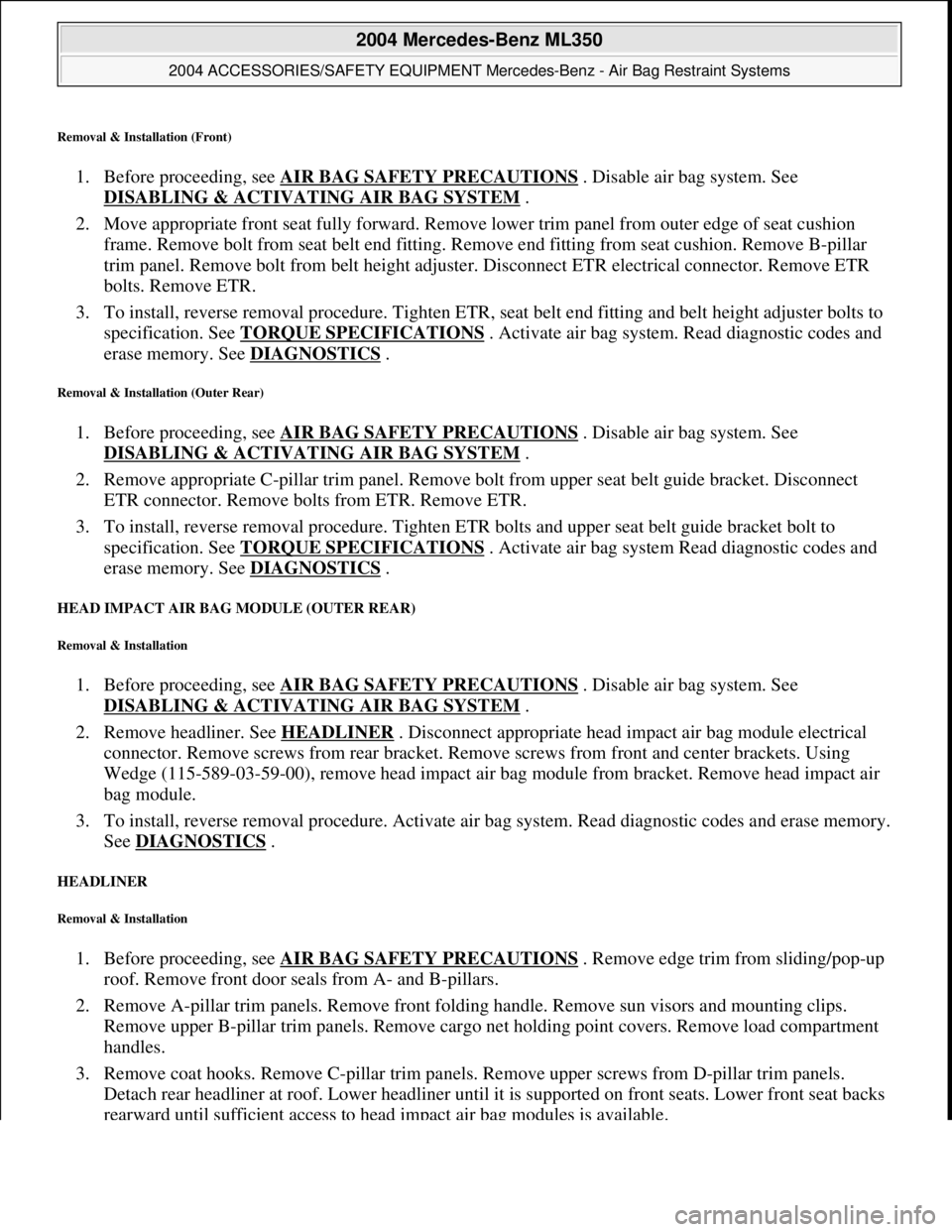
Removal & Installation (Front)
1. Before proceeding, see AIR BAG SAFETY PRECAUTIONS . Disable air bag system. See
DISABLING & ACTIVATI NG AIR BAG SYSTEM
.
2. Move appropriate front seat full y forward. Remove lower trim panel from outer edge of seat cushion
frame. Remove bolt from seat belt end fitting. Remove end fitting from seat cushion. Remove B-pillar
trim panel. Remove bolt from be lt height adjuster. Disconnect ET R electrical connector. Remove ETR
bolts. Remove ETR.
3. To install, reverse removal procedur e. Tighten ETR, seat belt end fitting and belt height adjuster bolts to
specification. See TORQUE SPECIFICATIONS
. Activate air bag system . Read diagnostic codes and
erase memory. See DIAGNOSTICS
.
Removal & Installation (Outer Rear)
1. Before proceeding, see AIR BAG SAFETY PRECAUTIONS . Disable air bag system. See
DISABLING & ACTIVATI NG AIR BAG SYSTEM
.
2. Remove appropriate C-pillar trim panel. Remove bolt from upper seat belt guide bracket. Disconnect
ETR connector. Remove bolts from ETR. Remove ETR.
3. To install, reverse removal proc edure. Tighten ETR bolts and upper seat belt guide bracket bolt to
specification. See TORQUE SPECIFICATIONS
. Activate air bag system Read diagnostic codes and
erase memory. See DIAGNOSTICS
.
HEAD IMPACT AIR BAG MODULE (OUTER REAR)
Removal & Installation
1. Before proceeding, see AIR BAG SAFETY PRECAUTIONS . Disable air bag system. See
DISABLING & ACTIVATI NG AIR BAG SYSTEM
.
2. Remove headliner. See HEADLINER
. Disconnect appropriate head im pact air bag module electrical
connector. Remove screws from rear bracket. Rem ove screws from front and center brackets. Using
Wedge (115-589-03-59-00), remove head impact air ba g module from bracket. Remove head impact air
bag module.
3. To install, reverse removal proce dure. Activate air bag system. Read diagnostic codes and erase memory.
See DIAGNOSTICS
.
HEADLINER
Removal & Installation
1. Before proceeding, see AIR BAG SAFETY PRECAUTIONS . Remove edge trim from sliding/pop-up
roof. Remove front door seals from A- and B-pillars.
2. Remove A-pillar trim panels. Remove front fold ing handle. Remove sun visors and mounting clips.
Remove upper B-pillar trim panels . Remove cargo net holding point c overs. Remove load compartment
handles.
3. Remove coat hooks. Remove C-pill ar trim panels. Remove upper screws from D-pillar trim panels.
Detach rear headliner at roof. Lower headliner until it is supported on front seats. Lower front seat backs
rearward until sufficient ac cess to head impact air ba
g modules is available.
2004 Mercedes-Benz ML350
2004 ACCESSORIES/SAFETY EQUIPMENT Merce des-Benz - Air Bag Restraint Systems
me
Saturday, October 02, 2010 3:40:40 PMPage 7 © 2006 Mitchell Repair Information Company, LLC.