1997 MERCEDES-BENZ ML500 roof
[x] Cancel search: roofPage 1634 of 4133
If a name is not available for the stored telephone number, the display is switched over and the
memory location and the telephone number are displayed.
By manually entering 1 or 2 numbers and subsequent actuation of the multifunction key" NAME " or
"NUM " the name stored under this memory location number or the stored telephone number are
indicated.
Pressing " SEND " button completes the desired connection. If no connection is to be completed, the
memory area can be exited by pressing the multifunction key" EXIT ".
Quick dial
When a one or two-digit number is entered and the " SEND " button is actuated the telephone number
stored under this memory location number is dialed.
By pressing and holding one of the number buttons 1 to 9 for more than 2 s the telephone number stored
under this memory location number is dialed. In this case it is not necessary to actuate the " SEND "
button.
Memory location functions 1 number is reserved for emergency !
Redialing
Pressing the" SEND " button without previously entering a telephone number calls up the last 5 selected
telephone numbers on the display. It is possible to select the desired telephone number by pressing the"
joystick " up or down. The connection is completed by actuating the" SEND " button. This area can be
exited by pressing the multifunction key" EXIT ".
Incoming calls
During an incoming call all other audio sources are set to mute and "CALL " appears on the display. The
call can be accepted by pressing the " SEND " button or terminated by pressing the" END " button.
During a call it is possible to continue dialing, e.g. enter a code number for an answering machine.
CASSETTE MODE, FUNCTION - GF82.85-P-2010GI
MODEL 163 as of 1.9.01 with CODE (522) Modular control system (MCS) radio USA with CODE (357)
Navigation system - additional unit with CODE (818b) Single CD player - additional unit with CODE
(491) U.S. version
GPS roof
antenna/telephone,
location/purpose/
design/function GF82.70-P-
4111A
2001 Mercedes-Benz ML320
1998-2005 ACCESSORIES & BODY, CAB Electrical System - Body - 163 Chassis
me
Saturday, October 02, 2010 3:30:06 PMPage 139 © 2006 Mitchell Repair Information Company, LLC.
Page 1638 of 4133
The navigation processor continuously calculates the location of the vehicle with the aid of the following
procedures:
GPS location finding
Basic location finding (dead reckoning)
Map-supported location finding (map matching)
The correct position is determined by continuously comparing the locating result of these three procedures.
Route calculation
The route is calculated in the navigation processor according to the destination entered, or automatically, after
deviating from the recommended route. The recommended route is stored in the navigation processor
Guidance
After the navigation processor has calculated the route, guidance is started. The driver receives continuous
information with the aid of guidance symbols appearing on the display of the radio and navigation unit
(A2/56) and voice announcements on the vehicle loudspeaker.
Audio 30 APS block diagramModel 163GF82.61-P-0002-02D
Model 168GF82.61-P-0002-02B
Model 170GF82.61-P-0002-02A
Models 208, 210GF82.61-P-0002-02C
Basic location finding (dead
reckoning), function GF82.61-P-3006D
Global positioning system (GPS)
location finding, function GF82.61-P-3007C
Map-assisted location finding,
function GF82.61-P-3008C
Route calculation, function GF82.61-P-3011E
Destination guidance, function GF82.61-P-3012D
Loading language, function GF82.61-P-3003B
Volume and tone settings GF82.60-P-2003A
Radio mode, function GF82.60-P-2001B
CD player mode, function GF82.60-P-2002B
Radio and navigation unit,
location/purpose/ design/function GF82.61-P-4109A
CTEL and GPS roof antenna,
location/purpose/ design/functionModels 163,
168,208.3,210GF82.70-P-4111A
Global positioning system antenna,
location/ purpose/design/functionModels 170, 208.4GF82.61-P-4106A
Antenna splitter, Model 163GF82.85-P-3107B
2001 Mercedes-Benz ML320
1998-2005 ACCESSORIES & BODY, CAB Electrical System - Body - 163 Chassis
me
Saturday, October 02, 2010 3:30:06 PMPage 143 © 2006 Mitchell Repair Information Company, LLC.
Page 1651 of 4133
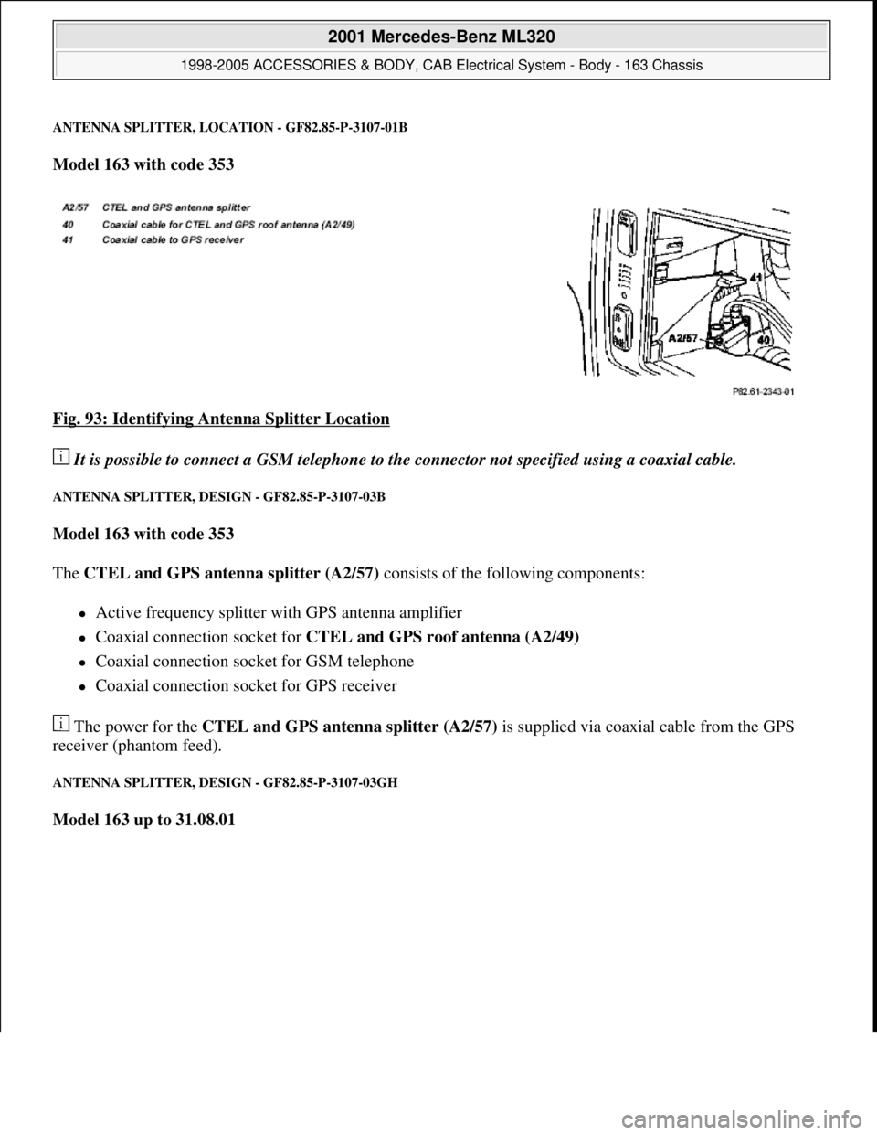
ANTENNA SPLITTER, LOCATION - GF82.85-P-3107-01B
Model 163 with code 353
Fig. 93: Identifying Antenna Splitter Location
It is possible to connect a GSM telephone to the connector not specified using a coaxial cable.
ANTENNA SPLITTER, DESIGN - GF82.85-P-3107-03B
Model 163 with code 353
The CTEL and GPS antenna splitter (A2/57) consists of the following components:
Active frequency splitter with GPS antenna amplifier
Coaxial connection socket for CTEL and GPS roof antenna (A2/49)
Coaxial connection socket for GSM telephone
Coaxial connection socket for GPS receiver
The power for the CTEL and GPS antenna splitter (A2/57) is supplied via coaxial cable from the GPS
receiver (phantom feed).
ANTENNA SPLITTER, DESIGN - GF82.85-P-3107-03GH
Model 163 up to 31.08.01
2001 Mercedes-Benz ML320
1998-2005 ACCESSORIES & BODY, CAB Electrical System - Body - 163 Chassis
me
Saturday, October 02, 2010 3:30:06 PMPage 156 © 2006 Mitchell Repair Information Company, LLC.
Page 1652 of 4133
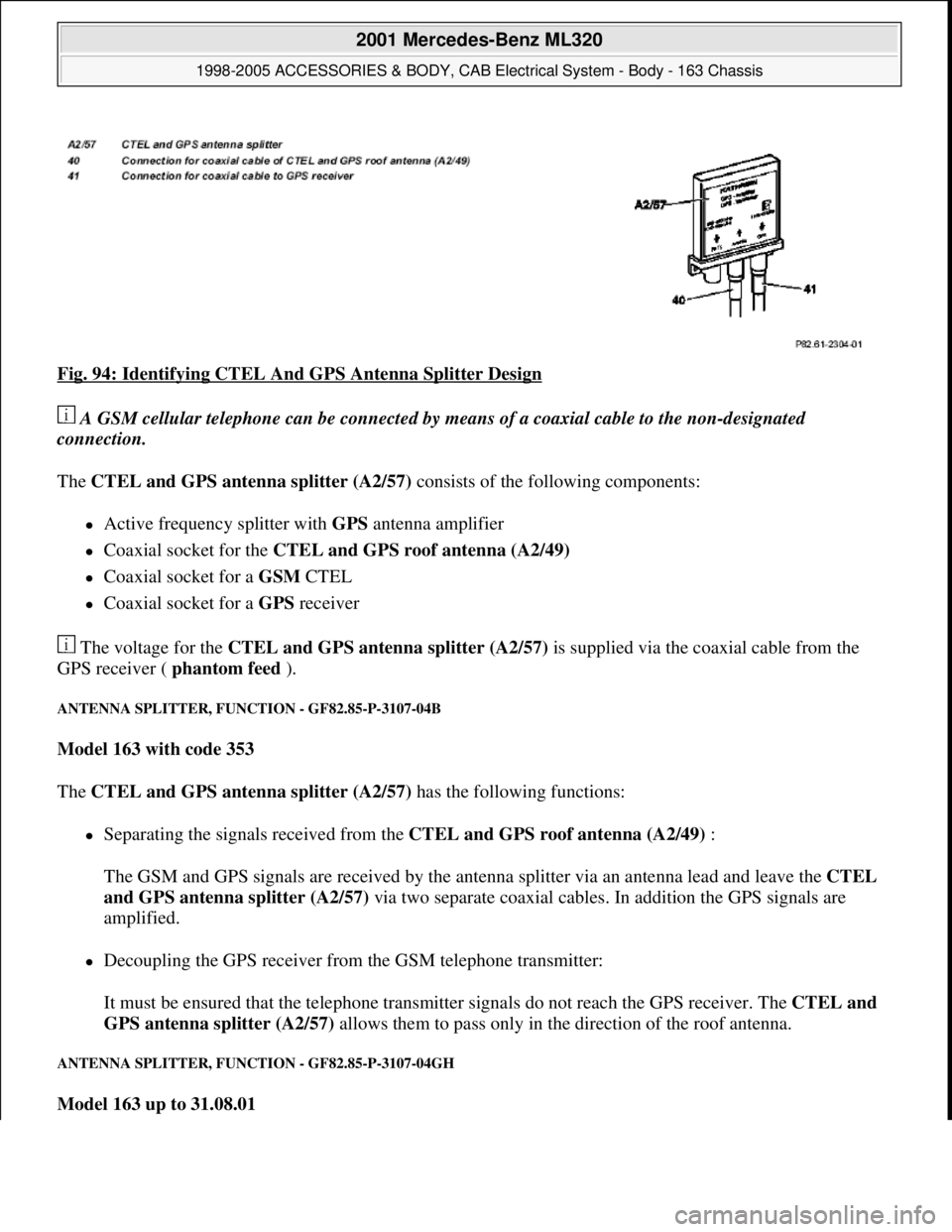
Fig. 94: Identifying CTEL And GPS Antenna Splitter Design
A GSM cellular telephone can be connected by means of a coaxial cable to the non-designated
connection.
The CTEL and GPS antenna splitter (A2/57) consists of the following components:
Active frequency splitter with GPS antenna amplifier
Coaxial socket for the CTEL and GPS roof antenna (A2/49)
Coaxial socket for a GSM CTEL
Coaxial socket for a GPS receiver
The voltage for the CTEL and GPS antenna splitter (A2/57) is supplied via the coaxial cable from the
GPS receiver ( phantom feed ).
ANTENNA SPLITTER, FUNCTION - GF82.85-P-3107-04B
Model 163 with code 353
The CTEL and GPS antenna splitter (A2/57) has the following functions:
Separating the signals received from the CTEL and GPS roof antenna (A2/49) :
The GSM and GPS signals are received by the antenna splitter via an antenna lead and leave the CTEL
and GPS antenna splitter (A2/57) via two separate coaxial cables. In addition the GPS signals are
amplified.
Decoupling the GPS receiver from the GSM telephone transmitter:
It must be ensured that the telephone transmitter signals do not reach the GPS receiver. The CTEL and
GPS antenna splitter (A2/57) allows them to pass only in the direction of the roof antenna.
ANTENNA SPLITTER, FUNCTION - GF82.85-P-3107-04GH
Model 163 up to 31.08.01
2001 Mercedes-Benz ML320
1998-2005 ACCESSORIES & BODY, CAB Electrical System - Body - 163 Chassis
me
Saturday, October 02, 2010 3:30:06 PMPage 157 © 2006 Mitchell Repair Information Company, LLC.
Page 1653 of 4133
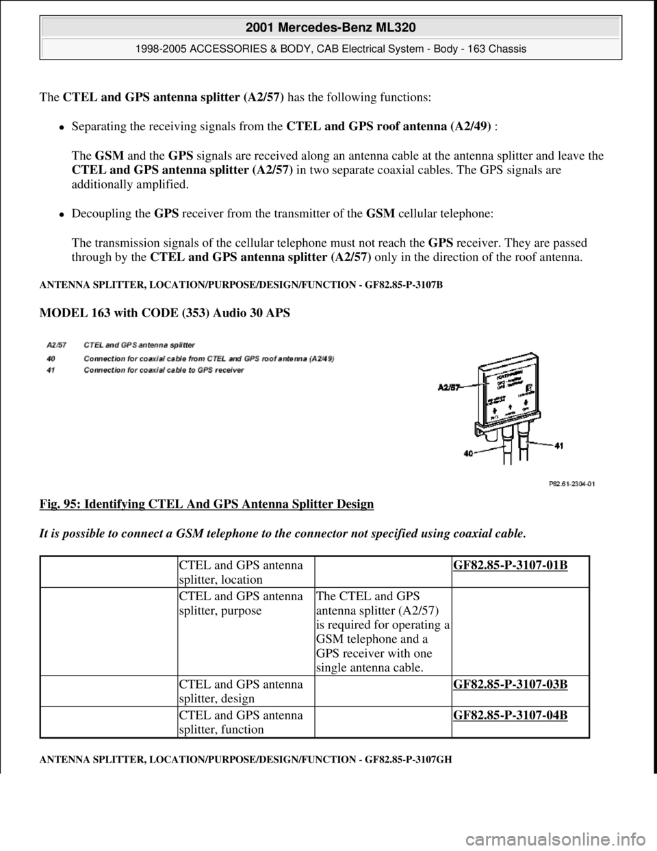
The CTEL and GPS antenna splitter (A2/57)has the following functions:
Separating the receiving signals from the CTEL and GPS roof antenna (A2/49) :
The GSM and the GPS signals are received along an antenna cable at the antenna splitter and leave the
CTEL and GPS antenna splitter (A2/57) in two separate coaxial cables. The GPS signals are
additionally amplified.
Decoupling the GPS receiver from the transmitter of the GSM cellular telephone:
The transmission signals of the cellular telephone must not reach the GPS receiver. They are passed
through by the CTEL and GPS antenna splitter (A2/57) only in the direction of the roof antenna.
ANTENNA SPLITTER, LOCATION/PURPOSE/DESIGN/FUNCTION - GF82.85-P-3107B
MODEL 163 with CODE (353) Audio 30 APS
Fig. 95: Identifying CTEL And GPS Antenna Splitter Design
It is possible to connect a GSM telephone to the connector not specified using coaxial cable.
ANTENNA SPLITTER, LOCATION/PURPOSE/DESIGN/FUNCTION - GF82.85-P-3107GH
CTEL and GPS antenna
splitter, location GF82.85-P-3107-01B
CTEL and GPS antenna
splitter, purposeThe CTEL and GPS
antenna splitter (A2/57)
is required for operating a
GSM telephone and a
GPS receiver with one
single antenna cable.
CTEL and GPS antenna
splitter, design GF82.85-P-3107-03B
CTEL and GPS antenna
splitter, function GF82.85-P-3107-04B
2001 Mercedes-Benz ML320
1998-2005 ACCESSORIES & BODY, CAB Electrical System - Body - 163 Chassis
me
Saturday, October 02, 2010 3:30:06 PMPage 158 © 2006 Mitchell Repair Information Company, LLC.
Page 1655 of 4133
OVERVIEW OF SYSTEM COMPONENTS FOR COCKPIT MANAGEMENT AND DATA SYSTEM (COMAND ),
LOCATION/TASK/DESIGN/FUNCTION - GF82.85-P-9997GHZ
MODEL 163
E-CALL BACKUP ANTENNA, LOCATION/PURPOSE - GF82.95-P-4205GH
MODEL 163 as of 1.9.01 with CODE (349) E-Call emergency call system with CODE (491) U.S. version
FM/AM antenna amplifier,
location/purpose/ design/function GF82.62-P-4101A
GPS/CTEL roof antenna
location/task/design/ function GF82.70-P-4111A
CD player with changer,
location/purpose/ design/functionWith CD changer
(code 819)GF82.64-P-3113GI
Modular control system (MCS)
function description contents GF82.85-P-
0995GIZ
Operating, display and control module,
location/ purpose/design/function GF82.85-P-3114GH
CD player with changer,
location/purpose/ design/functionwith (Code 819) CD
changerGF82.64-P-3113GH
Sound amplifier,
location/task/design/functionwith CODE (810)
sound systemGF82.62-P-3100GH
FM/AM antenna amplifier,
location/purpose/ design/functionMODELS 163, 168,
170, 208, 210GF82.62-P-4101A
GPS/telephone roof antenna,
location/task/ design/functionMODELS 163, 168,
208.3, 210GF82.70-P-4111A
Antenna splitter,
location/task/design/functionModel 163GF82.85-P-3107B
Contents, function description of
cockpit management and data system
(COMAND) GF82.85-P-
0997GHZ
2001 Mercedes-Benz ML320
1998-2005 ACCESSORIES & BODY, CAB Electrical System - Body - 163 Chassis
me
Saturday, October 02, 2010 3:30:06 PMPage 160 © 2006 Mitchell Repair Information Company, LLC.
Page 1656 of 4133
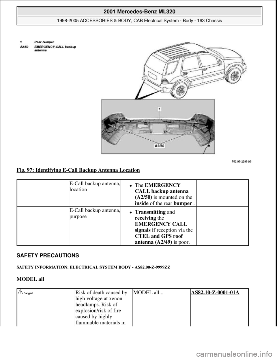
Fig. 97: Identifying E-Call Backup Antenna Location
SAFETY PRECAUTIONS
SAFETY INFORMATION: ELECTRICAL SYSTEM BODY - AS82.00-Z-9999ZZ
MODEL all
E-Call backup antenna,
locationThe EMERGENCY
CALL backup antenna
(A2/50) is mounted on the
inside of the rear bumper .
E-Call backup antenna,
purposeTransmitting and
receiving the
EMERGENCY CALL
signals if reception via the
CTEL and GPS roof
antenna (A2/49) is poor.
Risk of death caused by
high voltage at xenon
headlamps. Risk of
explosion/risk of fire
caused by highly
flammable materials in MODEL all...AS82.10-Z-0001-01A
2001 Mercedes-Benz ML320
1998-2005 ACCESSORIES & BODY, CAB Electrical System - Body - 163 Chassis
me
Saturday, October 02, 2010 3:30:06 PMPage 161 © 2006 Mitchell Repair Information Company, LLC.
Page 1669 of 4133
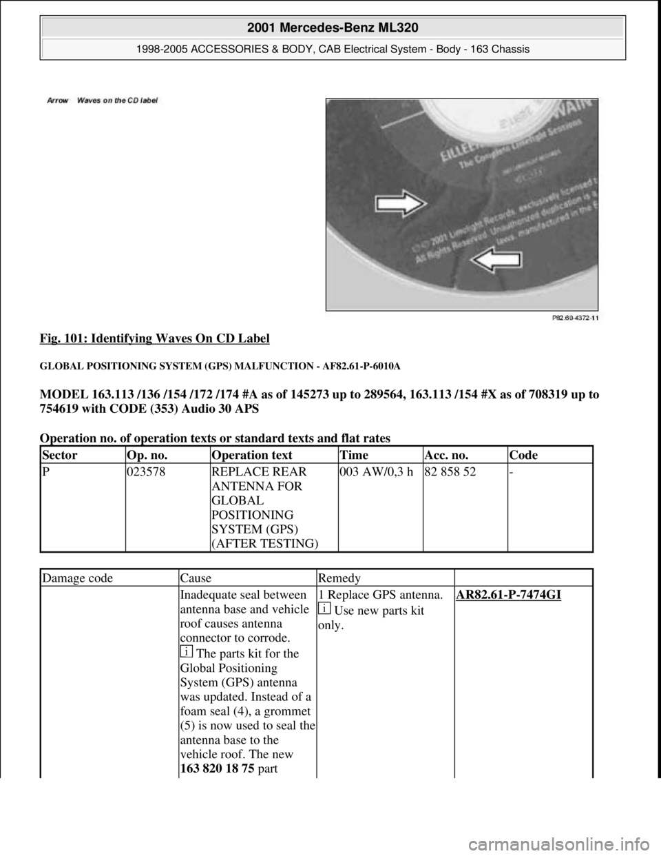
Fig. 101: Identifying Waves On CD Label
GLOBAL POSITIONING SYSTEM (GPS) MALFUNCTION - AF82.61-P-6010A
MODEL 163.113 /136 /154 /172 /174 #A as of 145273 up to 289564, 163.113 /154 #X as of 708319 up to
754619 with CODE (353) Audio 30 APS
Operation no. of operation texts or standard texts and flat rates
SectorOp. no.Operation textTimeAcc. no.Code
P023578REPLACE REAR
ANTENNA FOR
GLOBAL
POSITIONING
SYSTEM (GPS)
(AFTER TESTING)003 AW/0,3 h82 858 52-
Damage codeCauseRemedy
Inadequate seal between
antenna base and vehicle
roof causes antenna
connector to corrode.
The parts kit for the
Global Positioning
System (GPS) antenna
was updated. Instead of a
foam seal (4), a grommet
(5) is now used to seal the
antenna base to the
vehicle roof. The new
163 820 18 75 part 1 Replace GPS antenna.
Use new parts kit
only.AR82.61-P-7474GI
2001 Mercedes-Benz ML320
1998-2005 ACCESSORIES & BODY, CAB Electrical System - Body - 163 Chassis
me
Saturday, October 02, 2010 3:30:07 PMPage 174 © 2006 Mitchell Repair Information Company, LLC.