Page 1790 of 4133
REMOVE/INSTALL SPEAKER IN THE SIDE PANELING (REAR) - AR82.62-P-7837GH
MODEL 163.113 #A as of 289565, 163.113 #X as of 754620, 163.154 /174 #A as of 289565,
163.128 /157 /175 with CODE (810) Sound system
Fig. 196: Identifying Side Paneling Speaker Components (Rear)
REMOVE/INSTALL WOOFER - AR82.62-P-7839GH
MODEL 163.113 /128 /136 /154 /157 /172 /175 with CODE (810) Sound system
MODELS 163.174
Remove/install
1Remove rear roof frame
paneling (1) AR68.30-P-4470GH
2Remove screws (2) of left
rear speaker (H4/7) or
right rear speaker (H4/8)
from side paneling
3Remove left rear speaker
(H4/7) or right rear
speaker (H4/8) from the
side paneling Disconnect left rear
speaker connector
(H4/7x1) or right rear
speaker connector
(H4/8x1) from bracket
(3)
4Install in the reverse order
2001 Mercedes-Benz ML320
1998-2005 ACCESSORIES & BODY, CAB Electrical System - Body - 163 Chassis
me
Saturday, October 02, 2010 3:30:09 PMPage 295 © 2006 Mitchell Repair Information Company, LLC.
Page 1826 of 4133
Fig. 235: Identifying Retrofitting Diagnostic Cable
If a lead is already present in chamber 12 connect it to the green (gn) lead using a solder connector.
RETROFIT NAVIGATION SYSTEM AUDIO 30 APS - AN82.61-P-0001H
MODEL 163 up to 30.6.99 except CODE (819) 6-disk CD changer in trunk
MODEL 163 as of 1.7.99 in combination with CD changer with D2B fiber optic cable system
System illustration with GPS and telephone roof antenna
2001 Mercedes-Benz ML320
1998-2005 ACCESSORIES & BODY, CAB Electrical System - Body - 163 Chassis
me
Saturday, October 02, 2010 3:30:10 PMPage 331 © 2006 Mitchell Repair Information Company, LLC.
Page 1828 of 4133
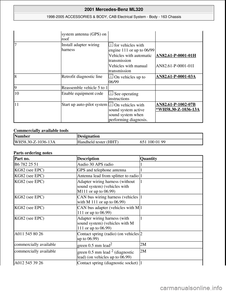
Commercially available tools
Parts ordering notes
system antenna (GPS) on
roof
7Install adapter wiring
harness for vehicles with
engine 111 or up to 06/99
Vehicles with automatic
transmissionAN82.61-P-0001-01H
Vehicles with manual
transmissionAN82.61-P-0001-01I
8Retrofit diagnostic line On vehicles up to
06/99AN82.61-P-0001-03A
9Reassemble vehicle 5 to 1
10Enable equipment code See operating
instructions
11Start up auto-pilot system On vehicles with
sound system active
sound system when
performing diagnosis.AN82.61-P-1002-07B
*WH58.30
-Z-1036-13A
NumberDesignation
WH58.30-Z-1036-13AHandheld tester (HHT)651 100 01 99
Part no.DescriptionQuantity
B6 782 25 51Audio 30 APS radio1
KG82 (see EPC)GPS and telephone antenna1
KG82 (see EPC)Antenna lead from splitter to radio1
KG82 (see EPC)Adapter wiring harness (without
sound system) (vehicles with
M111 or up to 06.99)1
KG82 (see EPC)CAN bus wiring harness (vehicles
with M 111 or up to 06.99)1
KG82 (see EPC)CAN bus adapter (vehicles with M
111 or up to 06.99)1
KG82 (see EPC)Adapter wiring harness (with
sound system) (vehicles with M
111 or up to 06.99)1
A011 545 80 26Contact spring (radio) (on vehicles
up to 06.99)2
commercially availablegreen 0.5 mm lead2 2M
commercially availablegreen 0.5 mm lead 2 (diagnostic
lead) (on vehicles up to 06.99)2M
A012 545 39 26Contact spring (diagnostic socket) 1
2001 Mercedes-Benz ML320
1998-2005 ACCESSORIES & BODY, CAB Electrical System - Body - 163 Chassis
me
Saturday, October 02, 2010 3:30:10 PMPage 333 © 2006 Mitchell Repair Information Company, LLC.
Page 1832 of 4133
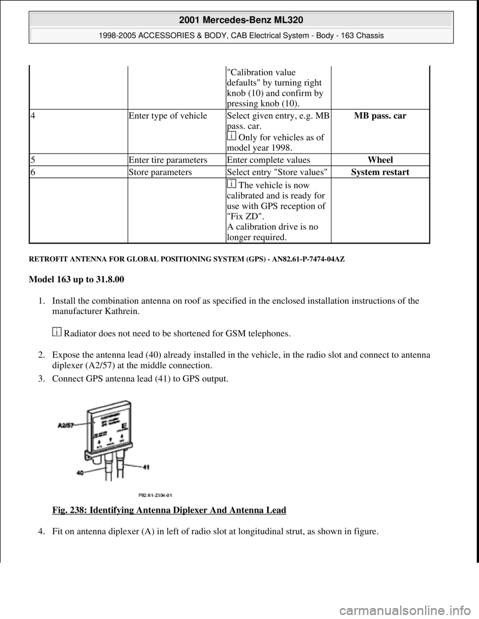
RETROFIT ANTENNA FOR GLOBAL POSITIONING SYSTEM (GPS) - AN82.61-P-7474-04AZ
Model 163 up to 31.8.00
1. Install the combination antenna on roof as specified in the enclosed installation instructions of the
manufacturer Kathrein.
Radiator does not need to be shortened for GSM telephones.
2. Expose the antenna lead (40) already installed in the vehicle, in the radio slot and connect to antenna
diplexer (A2/57) at the middle connection.
3. Connect GPS antenna lead (41) to GPS output.
Fig. 238: Identifying Antenna Diplexer And Antenna Lead
4. Fit on antenna diplexer (A) in left of radio slot at lon
gitudinal strut, as shown in figure.
"Calibration value
defaults" by turning right
knob (10) and confirm by
pressing knob (10).
4Enter type of vehicleSelect given entry, e.g. MB
pass. car.
Only for vehicles as of
model year 1998.MB pass. car
5Enter tire parametersEnter complete valuesWheel
6Store parametersSelect entry "Store values"System restart
The vehicle is now
calibrated and is ready for
use with GPS reception of
"Fix ZD".
A calibration drive is no
longer required.
2001 Mercedes-Benz ML320
1998-2005 ACCESSORIES & BODY, CAB Electrical System - Body - 163 Chassis
me
Saturday, October 02, 2010 3:30:11 PMPage 337 © 2006 Mitchell Repair Information Company, LLC.
Page 1846 of 4133
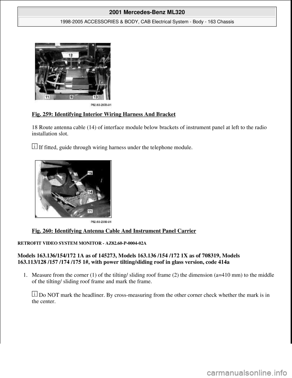
Fig. 259: Identifying Interior Wiring Harness And Bracket
18 Route antenna cable (14) of interface module below brackets of instrument panel at left to the radio
installation slot.
If fitted, guide through wiring harness under the telephone module.
Fig. 260: Identifying Antenna Cable And Instrument Panel Carrier
RETROFIT VIDEO SYSTEM MONITOR - AZ82.60-P-0004-02A
Models 163.136/154/172 1A as of 145273, Models 163.136 /154 /172 1X as of 708319, Models
163.113/128 /157 /174 /175 1#, with power tilting/sliding roof in glass version, code 414a
1. Measure from the corner (1) of the tilting/ sliding roof frame (2) the dimension (a=410 mm) to the middle
of the tilting/ sliding roof frame and mark the frame.
Do NOT mark the headliner. By cross-measuring from the other corner check whether the mark is in
the center.
2001 Mercedes-Benz ML320
1998-2005 ACCESSORIES & BODY, CAB Electrical System - Body - 163 Chassis
me
Saturday, October 02, 2010 3:30:11 PMPage 351 © 2006 Mitchell Repair Information Company, LLC.
Page 1847 of 4133
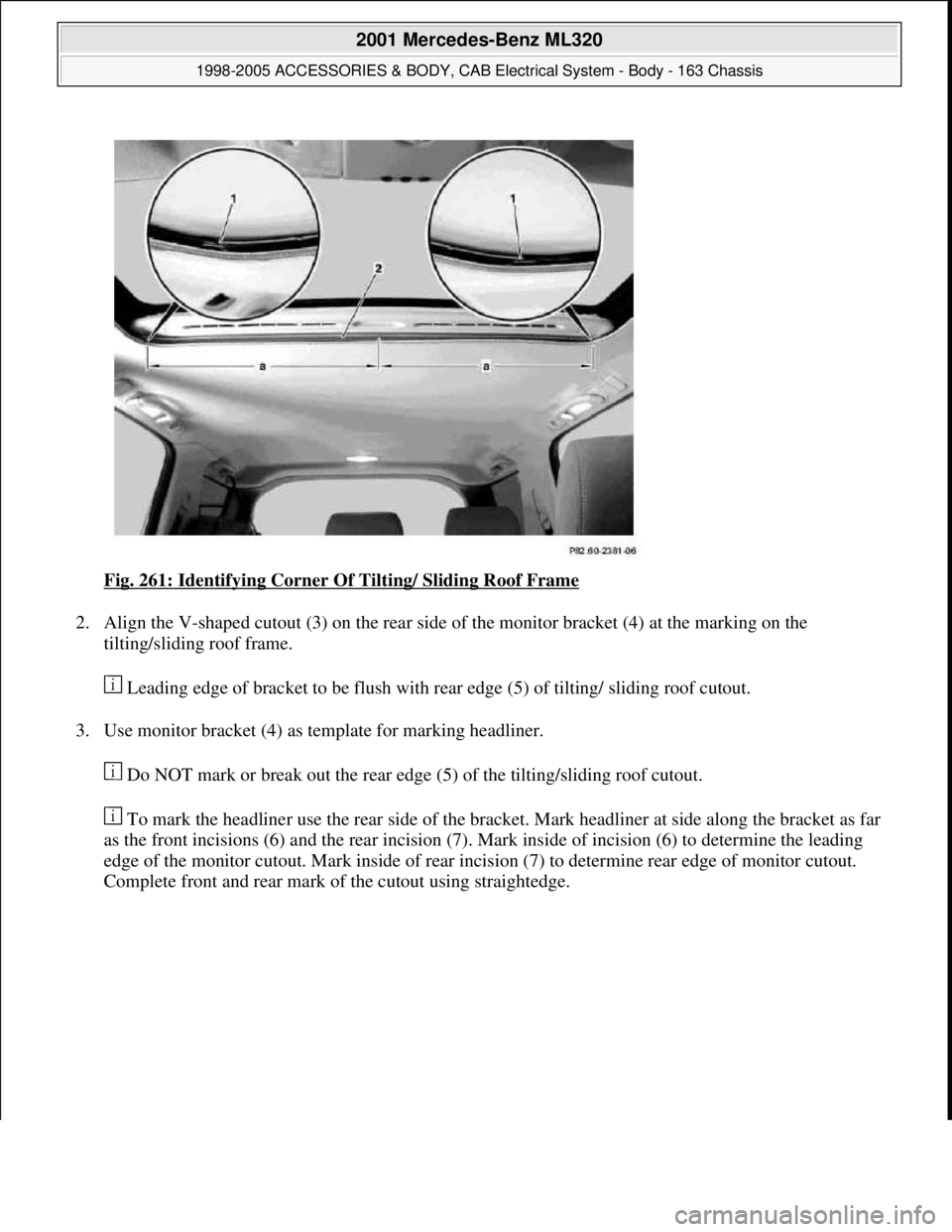
Fig. 261: Identifying Corner Of Tilting/ Sliding Roof Frame
2. Align the V-shaped cutout (3) on the rear side of the monitor bracket (4) at the marking on the
tilting/sliding roof frame.
Leading edge of bracket to be flush with rear edge (5) of tilting/ sliding roof cutout.
3. Use monitor bracket (4) as template for marking headliner.
Do NOT mark or break out the rear edge (5) of the tilting/sliding roof cutout.
To mark the headliner use the rear side of the bracket. Mark headliner at side along the bracket as far
as the front incisions (6) and the rear incision (7). Mark inside of incision (6) to determine the leading
edge of the monitor cutout. Mark inside of rear incision (7) to determine rear edge of monitor cutout.
Complete front and rear mark of the cutout usin
g straightedge.
2001 Mercedes-Benz ML320
1998-2005 ACCESSORIES & BODY, CAB Electrical System - Body - 163 Chassis
me
Saturday, October 02, 2010 3:30:11 PMPage 352 © 2006 Mitchell Repair Information Company, LLC.
Page 1848 of 4133
Fig. 262: Identifying V-Shaped Cutout On Rear Side Of Monitor Bracket
4. Remove marked area of the headliner.
Close paneling of the sliding/pop-up roof to prevent damage.
In order not to damage the headliner if the blade slips, cut inward starting from the corners. NEVER
remove the cutout until the headliner has been severed completely along the mark.
5. Fasten monitor wiring harness (8) at the white adhesive tape markings using the available clips (9) and
the attached, self-adhesive foamed material (10) to the right-hand A-pillar.
6. Route monitor wiring harness at top between the headliner and vehicle roof, next to the shock absorber at
the right-hand A-pillar.
Carefull
y pull headliner downward. Do not tear or bend headliner.
2001 Mercedes-Benz ML320
1998-2005 ACCESSORIES & BODY, CAB Electrical System - Body - 163 Chassis
me
Saturday, October 02, 2010 3:30:11 PMPage 353 © 2006 Mitchell Repair Information Company, LLC.
Page 1849 of 4133
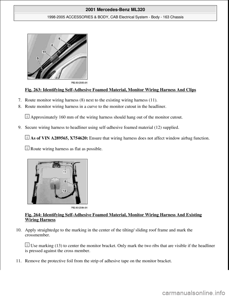
Fig. 263: Identifying Self-Adhesive Foamed Material, Monitor Wiring Harness And Clips
7. Route monitor wiring harness (8) next to the existing wiring harness (11).
8. Route monitor wiring harness in a curve to the monitor cutout in the headliner.
Approximately 160 mm of the wiring harness should hang out of the monitor cutout.
9. Secure wiring harness to headliner using self-adhesive foamed material (12) supplied.
As of VIN A289565, X754620: Ensure that wiring harness does not affect window airbag function.
Route wiring harness as flat as possible.
Fig. 264: Identifying Self
-Adhesive Foamed Material, Monitor Wiring Harness And Existing
Wiring Harness
10. Apply straightedge to the marking in the center of the tilting/ sliding roof frame and mark the
crossmember.
Use marking (13) to center the monitor bracket. Only mark the two ribs that are visible if the headliner
is pressed against the cross member.
11. Remove the protective foil from the strip of adhesive tape on the monitor bracket.
2001 Mercedes-Benz ML320
1998-2005 ACCESSORIES & BODY, CAB Electrical System - Body - 163 Chassis
me
Saturday, October 02, 2010 3:30:11 PMPage 354 © 2006 Mitchell Repair Information Company, LLC.