1997 MERCEDES-BENZ ML500 roof
[x] Cancel search: roofPage 1943 of 4133
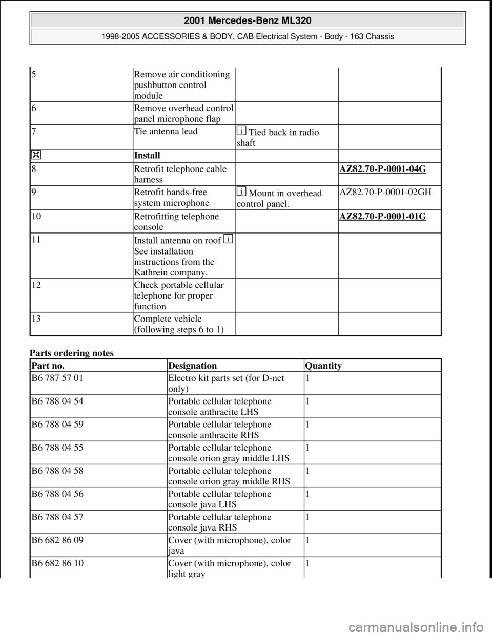
Parts ordering notes
5Remove air conditioning
pushbutton control
module
6Remove overhead control
panel microphone flap
7Tie antenna lead Tied back in radio
shaft
Install
8Retrofit telephone cable
harness AZ82.70-P-0001-04G
9Retrofit hands-free
system microphone Mount in overhead
control panel.AZ82.70-P-0001-02GH
10Retrofitting telephone
console AZ82.70-P-0001-01G
11Install antenna on roof
See installation
instructions from the
Kathrein company.
12Check portable cellular
telephone for proper
function
13Complete vehicle
(following steps 6 to 1)
Part no.DesignationQuantity
B6 787 57 01Electro kit parts set (for D-net
only)1
B6 788 04 54Portable cellular telephone
console anthracite LHS1
B6 788 04 59Portable cellular telephone
console anthracite RHS1
B6 788 04 55Portable cellular telephone
console orion gray middle LHS1
B6 788 04 58Portable cellular telephone
console orion gray middle RHS1
B6 788 04 56Portable cellular telephone
console java LHS1
B6 788 04 57Portable cellular telephone
console java RHS1
B6 682 86 09Cover (with microphone), color
java
1
B6 682 86 10Cover (with microphone), color
light gray1
2001 Mercedes-Benz ML320
1998-2005 ACCESSORIES & BODY, CAB Electrical System - Body - 163 Chassis
me
Saturday, October 02, 2010 3:30:14 PMPage 448 © 2006 Mitchell Repair Information Company, LLC.
Page 1945 of 4133
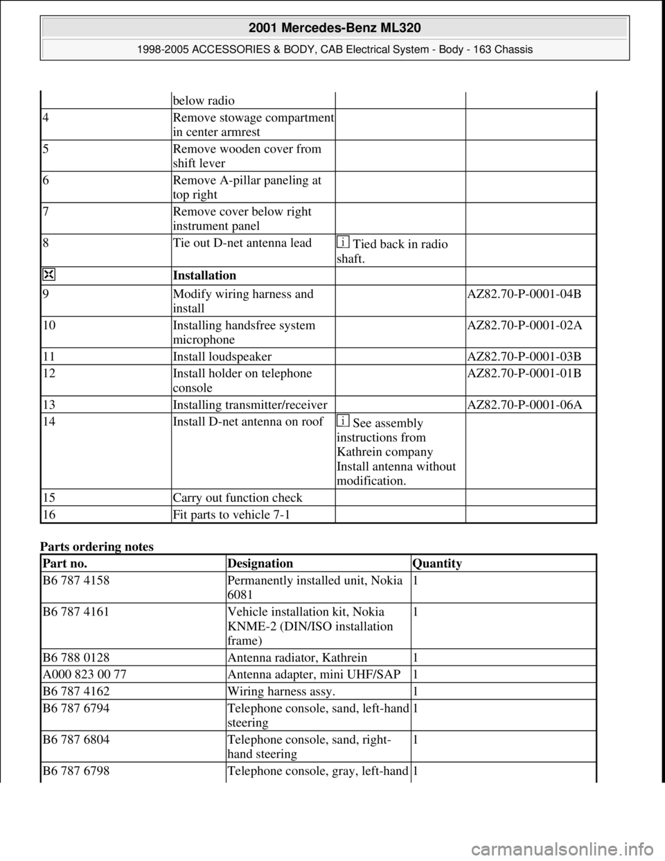
Parts ordering notes
below radio
4Remove stowage compartment
in center armrest
5Remove wooden cover from
shift lever
6Remove A-pillar paneling at
top right
7Remove cover below right
instrument panel
8Tie out D-net antenna lead Tied back in radio
shaft.
Installation
9Modify wiring harness and
install AZ82.70-P-0001-04B
10Installing handsfree system
microphone AZ82.70-P-0001-02A
11Install loudspeaker AZ82.70-P-0001-03B
12Install holder on telephone
console AZ82.70-P-0001-01B
13Installing transmitter/receiver AZ82.70-P-0001-06A
14Install D-net antenna on roof See assembly
instructions from
Kathrein company
Install antenna without
modification.
15Carry out function check
16Fit parts to vehicle 7-1
Part no.DesignationQuantity
B6 787 4158Permanently installed unit, Nokia
60811
B6 787 4161Vehicle installation kit, Nokia
KNME-2 (DIN/ISO installation
frame)1
B6 788 0128Antenna radiator, Kathrein1
A000 823 00 77Antenna adapter, mini UHF/SAP1
B6 787 4162Wiring harness assy.1
B6 787 6794Telephone console, sand, left-hand
steering1
B6 787 6804Telephone console, sand, right-
hand steering1
B6 787 6798Telephone console, gray, left-hand 1
2001 Mercedes-Benz ML320
1998-2005 ACCESSORIES & BODY, CAB Electrical System - Body - 163 Chassis
me
Saturday, October 02, 2010 3:30:14 PMPage 450 © 2006 Mitchell Repair Information Company, LLC.
Page 1947 of 4133
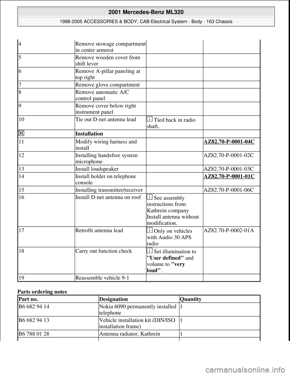
Parts ordering notes
4Remove stowage compartment
in center armrest
5Remove wooden cover from
shift lever
6Remove A-pillar paneling at
top right
7Remove glove compartment
8Remove automatic A/C
control panel
9Remove cover below right
instrument panel
10Tie out D-net antenna lead Tied back in radio
shaft.
Installation
11Modify wiring harness and
install AZ82.70-P-0001-04C
12Installing handsfree system
microphone AZ82.70-P-0001-02C
13Install loudspeaker AZ82.70-P-0001-03C
14Install holder on telephone
console AZ82.70-P-0001-01C
15Installing transmitter/receiver AZ82.70-P-0001-06C
16Install D-net antenna on roof See assembly
instructions from
Kathrein company
Install antenna without
modification.
17Retrofit antenna lead Only on vehicles
with Audio 30 APS
radioAZ82.70-P-0002-01A
18Carry out function check Set illumination to
"User defined" and
volume to "very
loud" .
19Reassemble vehicle 9-1
Part no.DesignationQuantity
B6 682 94 14Nokia 6090 permanently installed
telephone1
B6 682 94 13Vehicle installation kit (DIN/ISO
installation frame)1
B6 788 01 28Antenna radiator, Kathrein1
2001 Mercedes-Benz ML320
1998-2005 ACCESSORIES & BODY, CAB Electrical System - Body - 163 Chassis
me
Saturday, October 02, 2010 3:30:14 PMPage 452 © 2006 Mitchell Repair Information Company, LLC.
Page 1950 of 4133
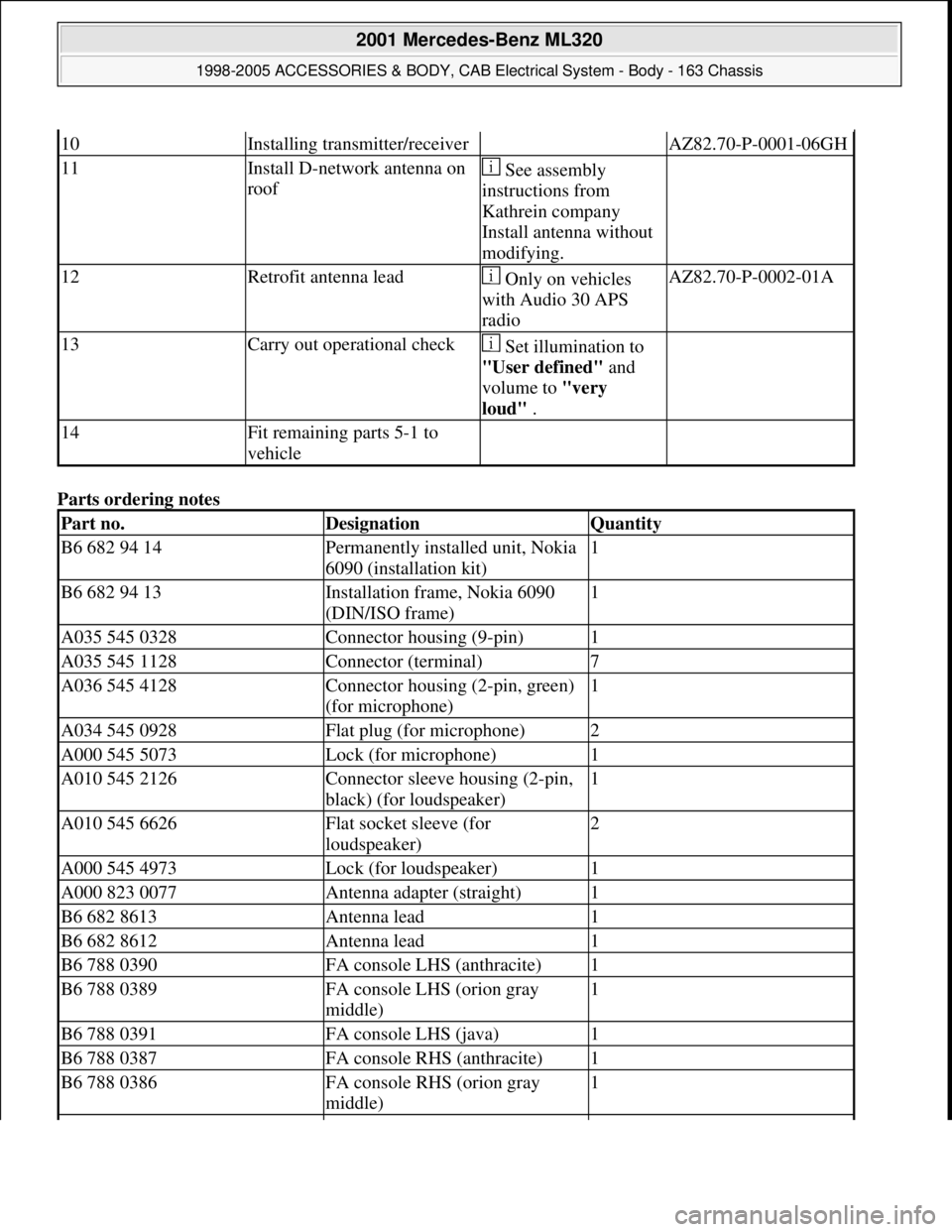
Parts ordering notes
10Installing transmitter/receiver AZ82.70-P-0001-06GH
11Install D-network antenna on
roof See assembly
instructions from
Kathrein company
Install antenna without
modifying.
12Retrofit antenna lead Only on vehicles
with Audio 30 APS
radioAZ82.70-P-0002-01A
13Carry out operational check Set illumination to
"User defined" and
volume to "very
loud" .
14Fit remaining parts 5-1 to
vehicle
Part no.DesignationQuantity
B6 682 94 14Permanently installed unit, Nokia
6090 (installation kit)1
B6 682 94 13Installation frame, Nokia 6090
(DIN/ISO frame)1
A035 545 0328Connector housing (9-pin)1
A035 545 1128Connector (terminal)7
A036 545 4128Connector housing (2-pin, green)
(for microphone)1
A034 545 0928Flat plug (for microphone)2
A000 545 5073Lock (for microphone)1
A010 545 2126Connector sleeve housing (2-pin,
black) (for loudspeaker)1
A010 545 6626Flat socket sleeve (for
loudspeaker)2
A000 545 4973Lock (for loudspeaker)1
A000 823 0077Antenna adapter (straight)1
B6 682 8613Antenna lead1
B6 682 8612Antenna lead1
B6 788 0390FA console LHS (anthracite)1
B6 788 0389FA console LHS (orion gray
middle)1
B6 788 0391FA console LHS (java)1
B6 788 0387FA console RHS (anthracite)1
B6 788 0386FA console RHS (orion gray
middle)1
2001 Mercedes-Benz ML320
1998-2005 ACCESSORIES & BODY, CAB Electrical System - Body - 163 Chassis
me
Saturday, October 02, 2010 3:30:14 PMPage 455 © 2006 Mitchell Repair Information Company, LLC.
Page 1955 of 4133
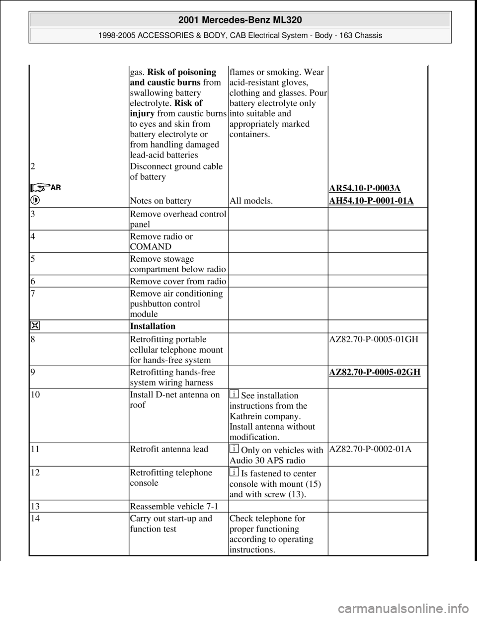
gas. Risk of poisoning
and caustic burns from
swallowing battery
electrolyte. Risk of
injury from caustic burns
to eyes and skin from
battery electrolyte or
from handling damaged
lead-acid batteriesflames or smoking. Wear
acid-resistant gloves,
clothing and glasses. Pour
battery electrolyte only
into suitable and
appropriately marked
containers.
2Disconnect ground cable
of battery
AR54.10-P-0003A
Notes on batteryAll models.AH54.10-P-0001-01A
3Remove overhead control
panel
4Remove radio or
COMAND
5Remove stowage
compartment below radio
6Remove cover from radio
7Remove air conditioning
pushbutton control
module
Installation
8Retrofitting portable
cellular telephone mount
for hands-free system AZ82.70-P-0005-01GH
9Retrofitting hands-free
system wiring harness AZ82.70-P-0005-02GH
10Install D-net antenna on
roof See installation
instructions from the
Kathrein company.
Install antenna without
modification.
11Retrofit antenna lead Only on vehicles with
Audio 30 APS radioAZ82.70-P-0002-01A
12Retrofitting telephone
console Is fastened to center
console with mount (15)
and with screw (13).
13Reassemble vehicle 7-1
14Carry out start-up and
function testCheck telephone for
proper functioning
according to operating
instructions.
2001 Mercedes-Benz ML320
1998-2005 ACCESSORIES & BODY, CAB Electrical System - Body - 163 Chassis
me
Saturday, October 02, 2010 3:30:14 PMPage 460 © 2006 Mitchell Repair Information Company, LLC.
Page 1958 of 4133
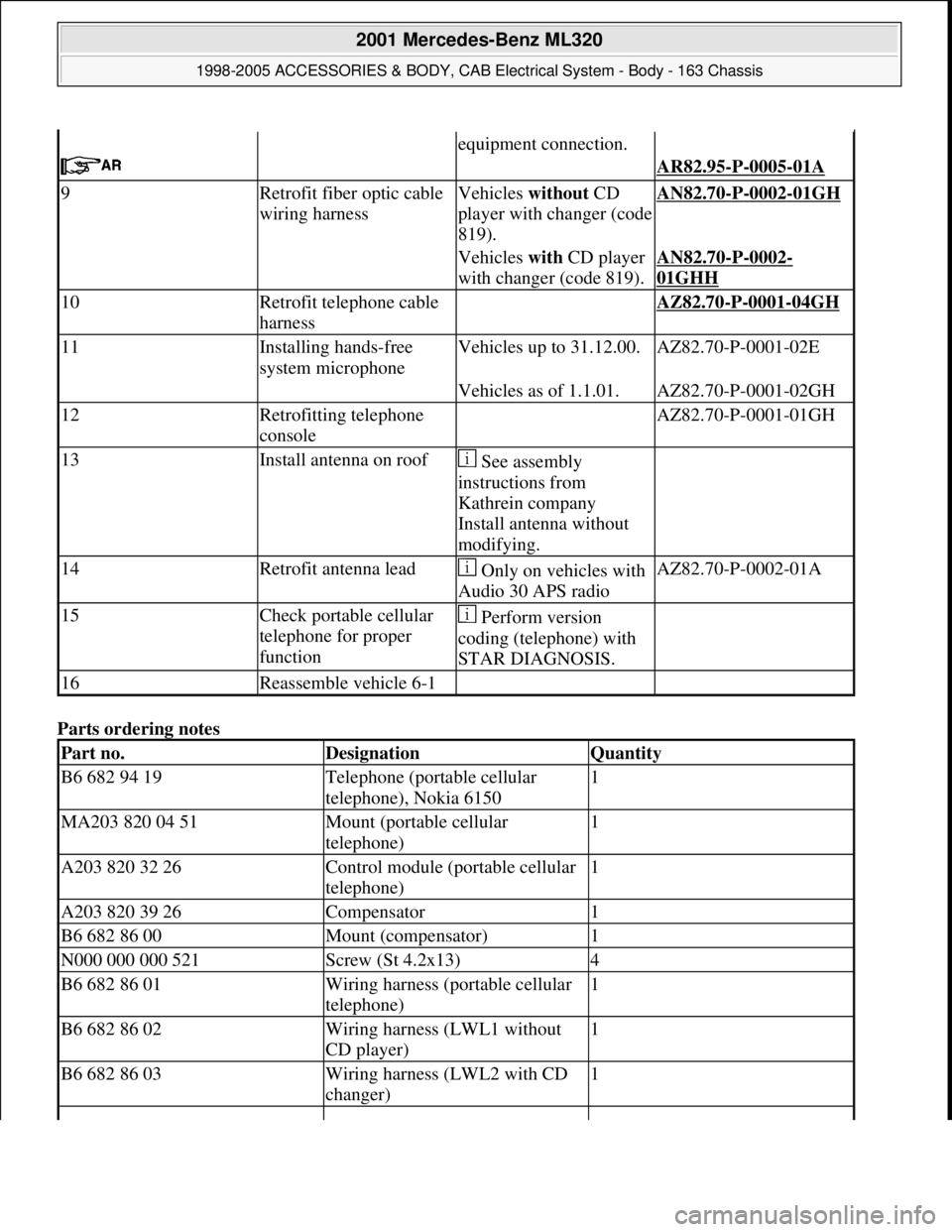
Parts ordering notes
equipment connection.
AR82.95-P-0005-01A
9Retrofit fiber optic cable
wiring harnessVehicles without CD
player with changer (code
819).AN82.70-P-0002-01GH
Vehicles with CD player
with changer (code 819).AN82.70-P-0002-
01GHH
10Retrofit telephone cable
harness AZ82.70-P-0001-04GH
11Installing hands-free
system microphoneVehicles up to 31.12.00.AZ82.70-P-0001-02E
Vehicles as of 1.1.01.AZ82.70-P-0001-02GH
12Retrofitting telephone
console AZ82.70-P-0001-01GH
13Install antenna on roof See assembly
instructions from
Kathrein company
Install antenna without
modifying.
14Retrofit antenna lead Only on vehicles with
Audio 30 APS radioAZ82.70-P-0002-01A
15Check portable cellular
telephone for proper
function Perform version
coding (telephone) with
STAR DIAGNOSIS.
16Reassemble vehicle 6-1
Part no.DesignationQuantity
B6 682 94 19Telephone (portable cellular
telephone), Nokia 61501
MA203 820 04 51Mount (portable cellular
telephone)1
A203 820 32 26Control module (portable cellular
telephone)1
A203 820 39 26Compensator1
B6 682 86 00Mount (compensator)1
N000 000 000 521Screw (St 4.2x13)4
B6 682 86 01Wiring harness (portable cellular
telephone)1
B6 682 86 02Wiring harness (LWL1 without
CD player)1
B6 682 86 03Wiring harness (LWL2 with CD
changer)1
2001 Mercedes-Benz ML320
1998-2005 ACCESSORIES & BODY, CAB Electrical System - Body - 163 Chassis
me
Saturday, October 02, 2010 3:30:14 PMPage 463 © 2006 Mitchell Repair Information Company, LLC.
Page 2030 of 4133
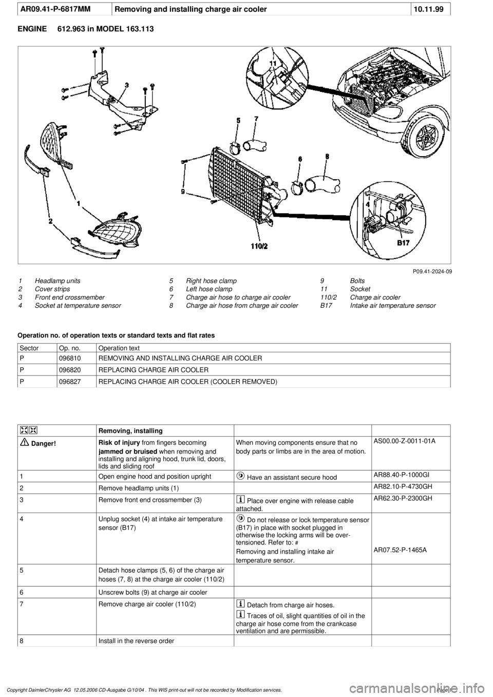
AR09.41-P-6817MM
Removing and installing charge air cooler
10.11.99
ENGINE
612.963 in MODEL 163.113
P09.41-2024-09
1
Headlamp units
2
Cover strips
3
Front end crossmember
4
Socket at temperature sensor
9
Bolts
11
Socket
110/2
Charge air cooler
B17
Intake air temperature sensor
5
Right hose clamp
6
Left hose clamp
7
Charge air hose to charge air cooler
8
Charge air hose from charge air cooler
Operation no. of operation texts or standard texts and flat rates
Sector
Op. no.
Operation text
P
096810
REMOVING AND INSTALLING CHARGE AIR COOLER
P
096820
REPLACING CHARGE AIR COOLER
P
096827
REPLACING CHARGE AIR COOLER (COOLER REMOVED)
Removing, installing
Danger!
Risk of injury
from fingers becoming
jammed or bruised
when removing and
installing and aligning hood, trunk lid, doors,
lids and sliding roof
When moving components ensure that no
body parts or limbs are in the area of motion.
AS00.00-Z-0011-01A
1
Open engine hood and position upright
Have an assistant secure hood
AR88.40-P-1000GI
2
Remove headlamp units (1)
AR82.10-P-4730GH
3
Remove front end crossmember (3)
Place over engine with release cable
attached.
AR62.30-P-2300GH
4
Unplug socket (4) at intake air temperature
sensor (B17)
Do not release or lock temperature sensor
(B17) in place with socket plugged in
otherwise the locking arms will be over-
tensioned. Refer to:
#
Removing and installing intake air
temperature sensor.
AR07.52-P-1465A
5
Detach hose clamps (5, 6) of the charge air
hoses (7, 8) at the charge air cooler (110/2)
6
Unscrew bolts (9) at charge air cooler
7
Remove charge air cooler (110/2)
Detach from charge air hoses.
Traces of oil, slight quantities of oil in the
charge air hose come from the crankcase
ventilation and are permissible.
8
Install in the reverse order
Copyright DaimlerChrysler AG 12.05.2006 CD-Ausgabe G/10/04 . This WIS print-out will not be recorde
d by Modification services.
Page 1
Page 2032 of 4133
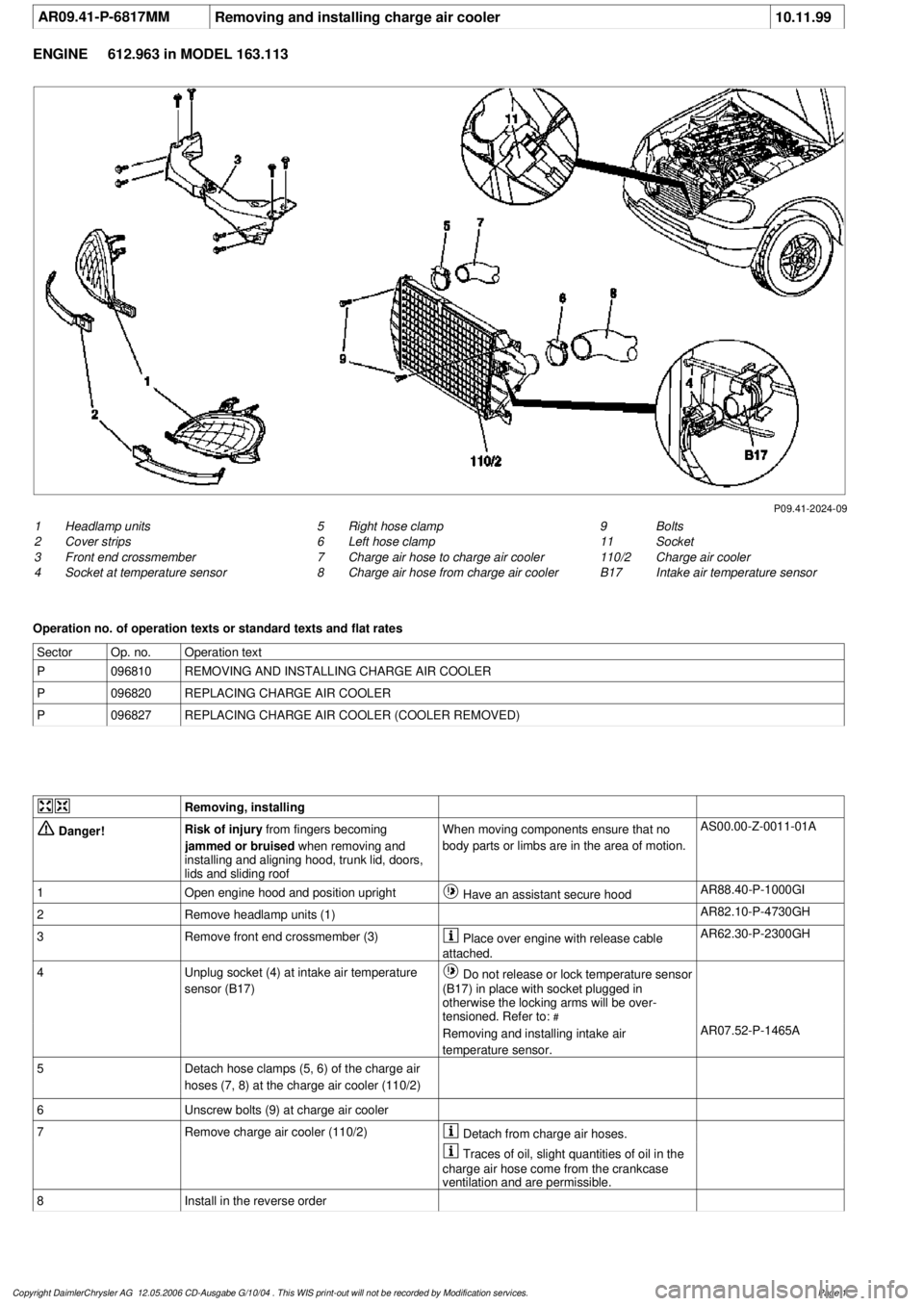
AR09.41-P-6817MM
Removing and installing charge air cooler
10.11.99
ENGINE
612.963 in MODEL 163.113
P09.41-2024-09
1
Headlamp units
2
Cover strips
3
Front end crossmember
4
Socket at temperature sensor
9
Bolts
11
Socket
110/2
Charge air cooler
B17
Intake air temperature sensor
5
Right hose clamp
6
Left hose clamp
7
Charge air hose to charge air cooler
8
Charge air hose from charge air cooler
Operation no. of operation texts or standard texts and flat rates
Sector
Op. no.
Operation text
P
096810
REMOVING AND INSTALLING CHARGE AIR COOLER
P
096820
REPLACING CHARGE AIR COOLER
P
096827
REPLACING CHARGE AIR COOLER (COOLER REMOVED)
Removing, installing
Danger!
Risk of injury
from fingers becoming
jammed or bruised
when removing and
installing and aligning hood, trunk lid, doors,
lids and sliding roof
When moving components ensure that no
body parts or limbs are in the area of motion.
AS00.00-Z-0011-01A
1
Open engine hood and position upright
Have an assistant secure hood
AR88.40-P-1000GI
2
Remove headlamp units (1)
AR82.10-P-4730GH
3
Remove front end crossmember (3)
Place over engine with release cable
attached.
AR62.30-P-2300GH
4
Unplug socket (4) at intake air temperature
sensor (B17)
Do not release or lock temperature sensor
(B17) in place with socket plugged in
otherwise the locking arms will be over-
tensioned. Refer to:
#
Removing and installing intake air
temperature sensor.
AR07.52-P-1465A
5
Detach hose clamps (5, 6) of the charge air
hoses (7, 8) at the charge air cooler (110/2)
6
Unscrew bolts (9) at charge air cooler
7
Remove charge air cooler (110/2)
Detach from charge air hoses.
Traces of oil, slight quantities of oil in the
charge air hose come from the crankcase
ventilation and are permissible.
8
Install in the reverse order
Copyright DaimlerChrysler AG 12.05.2006 CD-Ausgabe G/10/04 . This WIS print-out will not be recorde
d by Modification services.
Page 1