1997 MERCEDES-BENZ ML500 roof
[x] Cancel search: roofPage 2146 of 4133
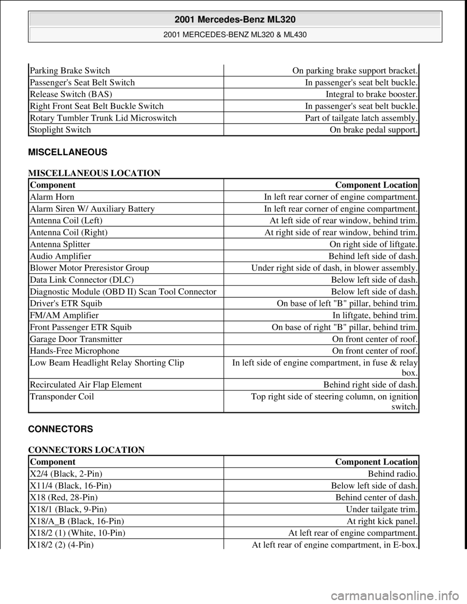
MISCELLANEOUS
MISCELLANEOUS LOCATION
CONNECTORS
CONNECTORS LOCATION
Parking Brake SwitchOn parking brake support bracket.
Passenger's Seat Belt SwitchIn passenger's seat belt buckle.
Release Switch (BAS)Integral to brake booster.
Right Front Seat Belt Buckle SwitchIn passenger's seat belt buckle.
Rotary Tumbler Trunk Lid MicroswitchPart of tailgate latch assembly.
Stoplight SwitchOn brake pedal support.
ComponentComponent Location
Alarm HornIn left rear corner of engine compartment.
Alarm Siren W/ Auxiliary BatteryIn left rear corner of engine compartment.
Antenna Coil (Left)At left side of rear window, behind trim.
Antenna Coil (Right)At right side of rear window, behind trim.
Antenna SplitterOn right side of liftgate.
Audio AmplifierBehind left side of dash.
Blower Motor Preresistor GroupUnder right side of dash, in blower assembly.
Data Link Connector (DLC)Below left side of dash.
Diagnostic Module (OBD II) Scan Tool ConnectorBelow left side of dash.
Driver's ETR SquibOn base of left "B" pillar, behind trim.
FM/AM AmplifierIn liftgate, behind trim.
Front Passenger ETR SquibOn base of right "B" pillar, behind trim.
Garage Door TransmitterOn front center of roof.
Hands-Free MicrophoneOn front center of roof.
Low Beam Headlight Relay Shorting ClipIn left side of engine compartment, in fuse & relay
box.
Recirculated Air Flap ElementBehind right side of dash.
Transponder CoilTop right side of steering column, on ignition
switch.
ComponentComponent Location
X2/4 (Black, 2-Pin)Behind radio.
X11/4 (Black, 16-Pin)Below left side of dash.
X18 (Red, 28-Pin)Behind center of dash.
X18/1 (Black, 9-Pin)Under tailgate trim.
X18/A_B (Black, 16-Pin)At right kick panel.
X18/2 (1) (White, 10-Pin)At left rear of engine compartment.
X18/2 (2) (4-Pin)At left rear of engine compartment, in E-box.
2001 Mercedes-Benz ML320
2001 MERCEDES-BENZ ML320 & ML430
me
Saturday, October 02, 2010 3:21:17 PMPage 6 © 2006 Mitchell Repair Information Company, LLC.
Page 2215 of 4133
being jammed or squeezed
when removing and
installing or aligning hoods,
doors, trunk lid/tailgate or
sliding roof.ensure that no body parts or
limbs are within the operating
range of moving parts.
1Open engine hoodModel 163.136/154 /172 #A up
to 145272,
Model 163.136 /154 /172 #X up
to 708318AR88.40-P-1000GH
Model 163.136 /154 /172 #A as
of 145273,
Model 163.136 /154 /172 #X
from 708319,
Model
163.113/128 /157 /174 /175AR88.40-P-1000GI
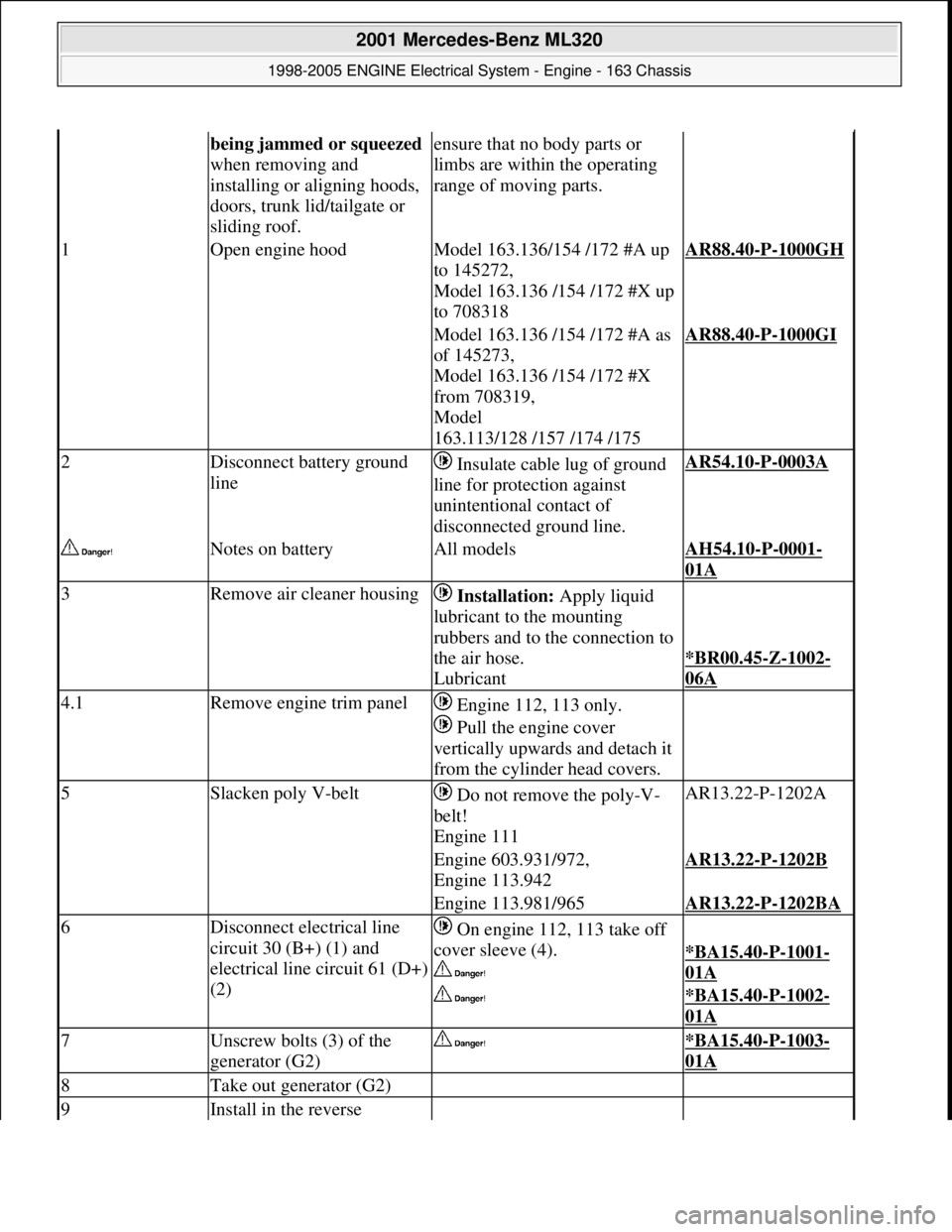
2Disconnect battery ground
line Insulate cable lug of ground
line for protection against
unintentional contact of
disconnected ground line.AR54.10-P-0003A
Notes on batteryAll modelsAH54.10-P-0001-
01A
3Remove air cleaner housing Installation: Apply liquid
lubricant to the mounting
rubbers and to the connection to
the air hose.
Lubricant
*BR00.45-Z-1002-
06A
4.1Remove engine trim panel Engine 112, 113 only.
Pull the engine cover
vertically upwards and detach it
from the cylinder head covers.
5Slacken poly V-belt Do not remove the poly-V-
belt!
Engine 111AR13.22-P-1202A
Engine 603.931/972,
Engine 113.942AR13.22-P-1202B
Engine 113.981/965AR13.22-P-1202BA
6Disconnect electrical line
circuit 30 (B+) (1) and
electrical line circuit 61 (D+)
(2) On engine 112, 113 take off
cover sleeve (4).
*BA15.40-P-1001-
01A
*BA15.40-P-1002-
01A
7Unscrew bolts (3) of the
generator (G2) *BA15.40-P-1003-
01A
8Take out generator (G2)
9Install in the reverse
2001 Mercedes-Benz ML320
1998-2005 ENGINE Electrical System - Engine - 163 Chassis
me
Saturday, October 02, 2010 3:18:54 PMPage 61 © 2006 Mitchell Repair Information Company, LLC.
Page 2517 of 4133
AR68.30-P-4470GH
Remove/install rear roof frame paneling
24.2.97
MODEL
163.113 /128 /136 /154 /157 /172 /174 /175
P68.30-0507-06
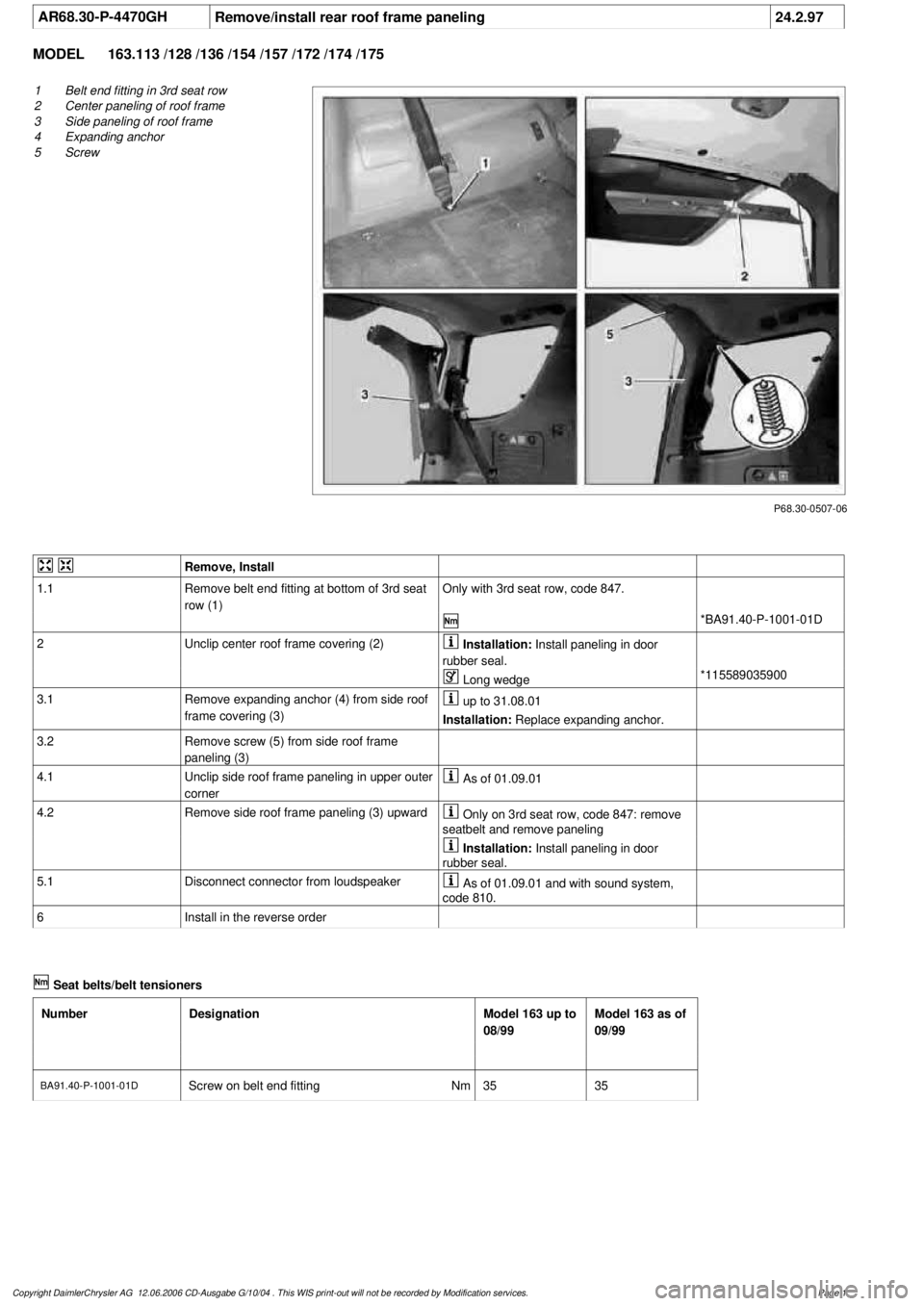
1
Belt end fitting in 3rd seat row
2
Center paneling of roof frame
3
Side paneling of roof frame
4
Expanding anchor
5
Screw
Remove, Install
1.1
Remove belt end fitting at bottom of 3rd seat
row (1)
Only with 3rd seat row, code 847.
*BA91.40-P-1001-01D
2
Unclip center roof frame covering (2)
Installation:
Install paneling in door
rubber seal.
Long wedge
*115589035900
3.1
Remove expanding anchor (4) from side roof
frame covering (3)
up to 31.08.01
Installation:
Replace expanding anchor.
3.2
Remove screw (5) from side roof frame
paneling (3)
4.1Unclip side roof frame paneling in upper outer
corner
As of 01.09.01
4.2
Remove side roof frame paneling (3) upward
Only on 3rd seat row, code 847: remove
seatbelt and remove paneling
Installation:
Install paneling in door
rubber seal.
5.1
Disconnect connector from loudspeaker
As of 01.09.01 and with sound system,
code 810.
6
Install in the reverse order
Seat belts/belt tensioners
Number
Designation
Model 163 up to
08/99
Model 163 as of
09/99
BA91.40-P-1001-01D
Screw on belt end fitting
Nm
3535
Copyright DaimlerChrysler AG 12.06.2006 CD-Ausgabe G/10/04 . This WIS print-out will not be recorde
d by Modification services.
Page 1
Page 2583 of 4133
AR07.16-P-1100MM
Remove, install fuel cooler
5.11.99
ENGINE
612.963 in MODELS 163.113
P47.00-2042-12
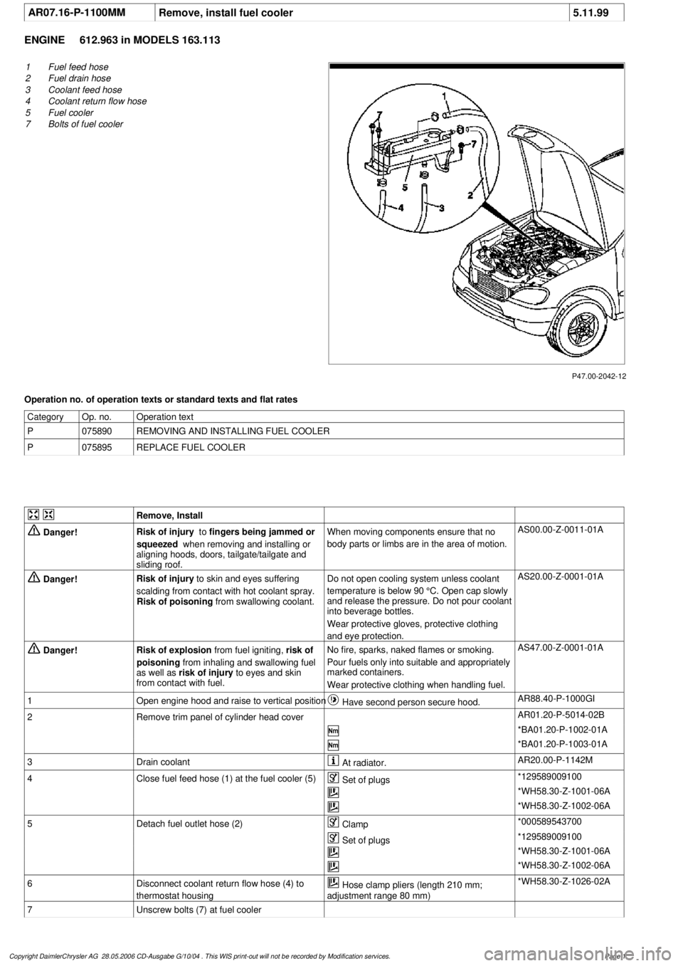
1
Fuel feed hose
2
Fuel drain hose
3
Coolant feed hose
4
Coolant return flow hose
5
Fuel cooler
7
Bolts of fuel cooler
Operation no. of operation texts or standard texts and flat rates
Category
Op. no.
Operation text
P
075890
REMOVING AND INSTALLING FUEL COOLER
P
075895
REPLACE FUEL COOLER
Remove, Install
Danger!
Risk of injury
to
fingers being jammed or
squeezed
when removing and installing or
aligning hoods, doors, tailgate/tailgate and
sliding roof.
When moving components ensure that no
body parts or limbs are in the area of motion.
AS00.00-Z-0011-01A
Danger!
Risk of injury
to skin and eyes suffering
scalding from contact with hot coolant spray.
Risk of poisoning
from swallowing coolant.
Do not open cooling system unless coolant
temperature is below 90 °C. Open cap slowly
and release the pressure. Do not pour coolant
into beverage bottles.
Wear protective gloves, protective clothing
and eye protection.
AS20.00-Z-0001-01A
Danger!
Risk of explosion
from fuel igniting,
risk of
poisoning
from inhaling and swallowing fuel
as well as
risk of injury
to eyes and skin
from contact with fuel.
No fire, sparks, naked flames or smoking.
Pour fuels only into suitable and appropriately
marked containers.
Wear protective clothing when handling fuel.
AS47.00-Z-0001-01A
1
Open engine hood and raise to vertical position
Have second person secure hood.
AR88.40-P-1000GI
2
Remove trim panel of cylinder head cover
AR01.20-P-5014-02B
*BA01.20-P-1002-01A
*BA01.20-P-1003-01A
3
Drain coolant
At radiator.
AR20.00-P-1142M
4
Close fuel feed hose (1) at the fuel cooler (5)
Set of plugs
*129589009100
*WH58.30-Z-1001-06A
*WH58.30-Z-1002-06A
5
Detach fuel outlet hose (2)
Clamp
*000589543700
Set of plugs
*129589009100
*WH58.30-Z-1001-06A
*WH58.30-Z-1002-06A
6
Disconnect coolant return flow hose (4) to
thermostat housing
Hose clamp pliers (length 210 mm;
adjustment range 80 mm)
*WH58.30-Z-1026-02A
7
Unscrew bolts (7) at fuel cooler
Copyright DaimlerChrysler AG 28.05.2006 CD-Ausgabe G/10/04 . This WIS print-out will not be recorde
d by Modification services.
Page 1
Page 2591 of 4133
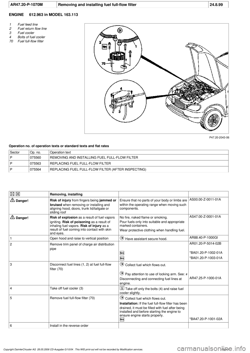
AR47.20-P-1070M
Removing and installing fuel full-flow filter
24.8.99
ENGINE
612.963 in MODEL 163.113
P47.20-2043-06
1
Fuel feed line
2
Fuel return flow line
3
Fuel cooler
4
Bolts of fuel cooler
70
Fuel full-flow filter
Operation no. of operation texts or standard texts and flat rates
Sector
Op. no.
Operation text
P
075560
REMOVING AND INSTALLING FUEL FULL-FLOW FILTER
P
075563
REPLACING FUEL FULL-FLOW FILTER
P
075564
REPLACING FUEL FULL-FLOW FILTER (AFTER INSPECTING)
Removing, installing
Danger!
Risk of injury
from fingers being
jammed or
bruised
when removing or installing and
aligning hood, doors, trunk lid/tailgate or
sliding roof
Ensure that no parts of your body or limbs are
within the operating range when moving such
components.
AS00.00-Z-0011-01A
Danger!
Risk of explosion
as a result of fuel vapors
igniting.
Risk of poisoning
as a result of
inhaling fuel vapors.
Risk of injury
as a
result of fuel coming into contact with skin
and eyes.
No fire, naked flame or smoking.
Pour fuels only into suitable and appropriate
marked containers.
Wear protective clothing when handling fuel.
AS47.00-Z-0001-01A
1
Open hood and raise to vertical position
Have assistant secure hood.
AR88.40-P-1000GI
2
Remove trim panel of charge air distribution
pipe
AR01.20-P-5014-02B
*BA01.20-P-1002-01A
*BA01.20-P-1003-01A
3
Disconnect fuel lines (1, 2) at fuel full-flow
filter (70)
Collect fuel which flows out.
Pay attention to use of locking arm. See:
#
Disconnecting and connecting fuel lines at
engine.
AR47.25-P-1000-01A
4
Take off fuel cooler (3)
Take off only the bolts (4) and raise fuel
cooler slightly.
5
Remove fuel full-flow filter (70)
Collect fuel which flows out.
Installation:
If the fuel full-flow filter has been
drained, it must be filled with fuel after being
installed and before starting the engine to
ensure engine starts properly.
*BA47.20-P-1001-02A
6
Install in the reverse order
Copyright DaimlerChrysler AG 28.05.2006 CD-Ausgabe G/10/04 . This WIS print-out will not be recorde
d by Modification services.
Page 1
Page 2656 of 4133
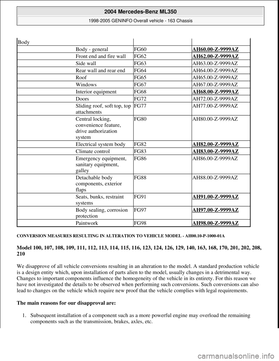
CONVERSION MEASURES RESULTING IN ALTERATION TO VEHICLE MODEL - AH00.10-P-1000-01A
Model 100, 107, 108, 109, 111, 112, 113, 114, 115, 116, 123, 124, 126, 129, 140, 163, 168, 170, 201, 202, 208,
210
We disapprove of all vehicle conversions resulting in an alteration to the model. A standard production vehicle
is a design entity which, upon installation of parts alien to the model, usually changes in a detrimental way.
Changes to important components influence the homogeneity of the vehicle in its entirety. For this reason we
have not investigated the details to be observed when performing such conversions. Such conversions can also
lead to changes on the vehicle which require new proof that the vehicle complies with legal requirements.
The main reasons for our disapproval are:
1. Subsequent installation of a component such as a more powerful engine may overload the remaining
components such as the transmission, brakes, axles, etc.
Body
Body - generalFG60AH60.00-Z-9999AZ
Front end and fire wallFG62AH62.00-Z-9999AZ
Side wallFG63AH63.00-Z-9999AZ
Rear wall and rear endFG64AH64.00-Z-9999AZ
RoofFG65AH65.00-Z-9999AZ
WindowsFG67AH67.00-Z-9999AZ
Interior equipmentFG68AH68.00-Z-9999AZ
DoorsFG72AH72.00-Z-9999AZ
Sliding roof, soft top, top
attachmentsFG77AH77.00-Z-9999AZ
Central locking,
convenience feature,
drive authorization
systemFG80AH80.00-Z-9999AZ
Electrical system bodyFG82AH82.00-Z-9999AZ
Climate controlFG83AH83.00-Z-9999AZ
Emergency equipment,
sanitary equipment,
galleyFG86AH86.00-Z-9999AZ
Detachable body
components, exterior
flapsFG88AH88.00-Z-9999AZ
Seats, bunks, restraint
systemsFG91AH91.00-Z-9999AZ
Body sealing, corrosion
protectionFG97AH97.00-Z-9999AZ
PaintworkFG98AH98.00-Z-9999AZ
2004 Mercedes-Benz ML350
1998-2005 GENINFO Overall vehicle - 163 Chassis
me
Saturday, October 02, 2010 3:47:44 PMPage 11 © 2006 Mitchell Repair Information Company, LLC.
Page 2868 of 4133
Align vehicle between the columns of the lifting platform and position the four support plates at the
lifting platform support points specified by the vehicle manufacturer.
RISK OF ACCIDENT AND INJURY
Please make sure that:
The vehicle is centered lengthwise and crosswise between the lifting platform columns.
The support plates on the lifting platform support points are all positioned at the same height.
The vehicle is first raised a few inches (wheels are still touching the ground) and the position and fit of
the support plates and lift points are checked before raising the vehicle to the full lifted position.
The vehicle is not raised off the lifting platform plates when components are being supported.
If the arms of the lifting platform or the support plates are not positioned properly, or if components of the
vehicle are supported so that the vehicle raises off the platform, then the vehicle can slip off the platform and
cause life-threatening injuries to you or other people.
Before removing axles and assemblies from the vehicle, make sure the vehicle is secured to the platform or that
sand bags are used to balance the vehicle out.
Otherwise the vehicle could tip because of the uneven distribution of weight. This could cause life-threatening
injuries to you or other people.
RISK OF INJURY CAUSED BY FINGERS BEING JAMMED OR PINCHED WHEN REMOVING, INSTALLING OR
ALIGNING HOODS, DOORS, TRUNK LID/ REAR-END DOOR OR SLIDING ROOF. - AS00.00-Z-0011-01A
When moving components, ensure that no body parts or limbs are within the operating range of moving
parts.
Risk of injury
When working on hoods, doors, trunk lids/tailgates and sliding roofs and on their connecting mechanisms,
serious injuries can occur due to cutting, jamming or pinching of body parts like fingers and hands.
Safety instructions/precautions
Be careful when working in hazardous areas.
When moving components, secure the movement area of the mechanism to prevent interference.
Use special tool or other means to ensure safe distance to dangerous areas. NOTE: In Germany, lift platform operators must observe the following regulations and
guidelines: "Berufsgenossenschaftvorschrift (BGV) D29 fur Hebebuhnen" and
the guidelines issued by the lift platform manufacturer. In other countries,
operators must comply with all relevant statutory and accident prevention
regulations.
2004 Mercedes-Benz ML350
1998-2005 GENINFO Overall vehicle - 163 Chassis
me
Saturday, October 02, 2010 3:47:47 PMPage 223 © 2006 Mitchell Repair Information Company, LLC.
Page 2878 of 4133
running engine or drive
train.
Risk of injury. Moving parts
can pinch, crush or, in
extreme cases even sever
extremities.MODEL allAS00.00-Z-0009-01A
Risk of injury caused by
fingers being jammed or
pinched when removing,
installing or aligning hoods,
doors, trunk lid/rear-end
door or sliding roof.MODEL allAS00.00-Z-0011-01A
Risk of injury from fingers
being pinched or jammed
when working on gas struts
under pressureMODEL allAS00.00-Z-0012-01A
Risk of injury to skin or
eyes from hydraulic fluid
spraying out under pressure.
Risk of poisoning from
swallowing hydraulic fluid.MODEL allAS00.00-Z-0013-01A
Risk of injury. Rubber
mounts and bearing parts
can suddenly come loose
during installation/ removal
and shoot wildly through
the air.MODEL allAS00.00-Z-0014-01A
Risk of explosion from
pressurized spray cansMODEL 100, 107, 108,
109, 111, 112, 113, 114,
115, 116, 123, 124, 126,
129, 140, 163, 168, 170,
201, 202, 208, 210, 215,
216, 220, 221, 251 ...AS00.00-Z-0015-01A
Risk of poisoning caused by
inhaling vapors or
swallowing adhesive. Risk
of injury caused by glue
coming into contact with
skin and eyesMODEL 163, 169, 199,
204, 209, 211, 215, 216,
219, 221, 240, 245, 397,
461, 463, 613, 638, 639,
671, 684, 901, 902, 903,
904 ...AS00.00-Z-0016-01A
Injury hazard of cutting or
scraping on sharp vehicle
partsMODEL allAS00.00-Z-0017-01A
Risk of explosion caused by
escaping natural gas or an
overheated compressed-gas
tanks when working on MODEL 901, 902, 903,
904, 957.AS00.00-Z-0018-01A
2004 Mercedes-Benz ML350
1998-2005 GENINFO Overall vehicle - 163 Chassis
me
Saturday, October 02, 2010 3:47:48 PMPage 233 © 2006 Mitchell Repair Information Company, LLC.