Page 3592 of 4133

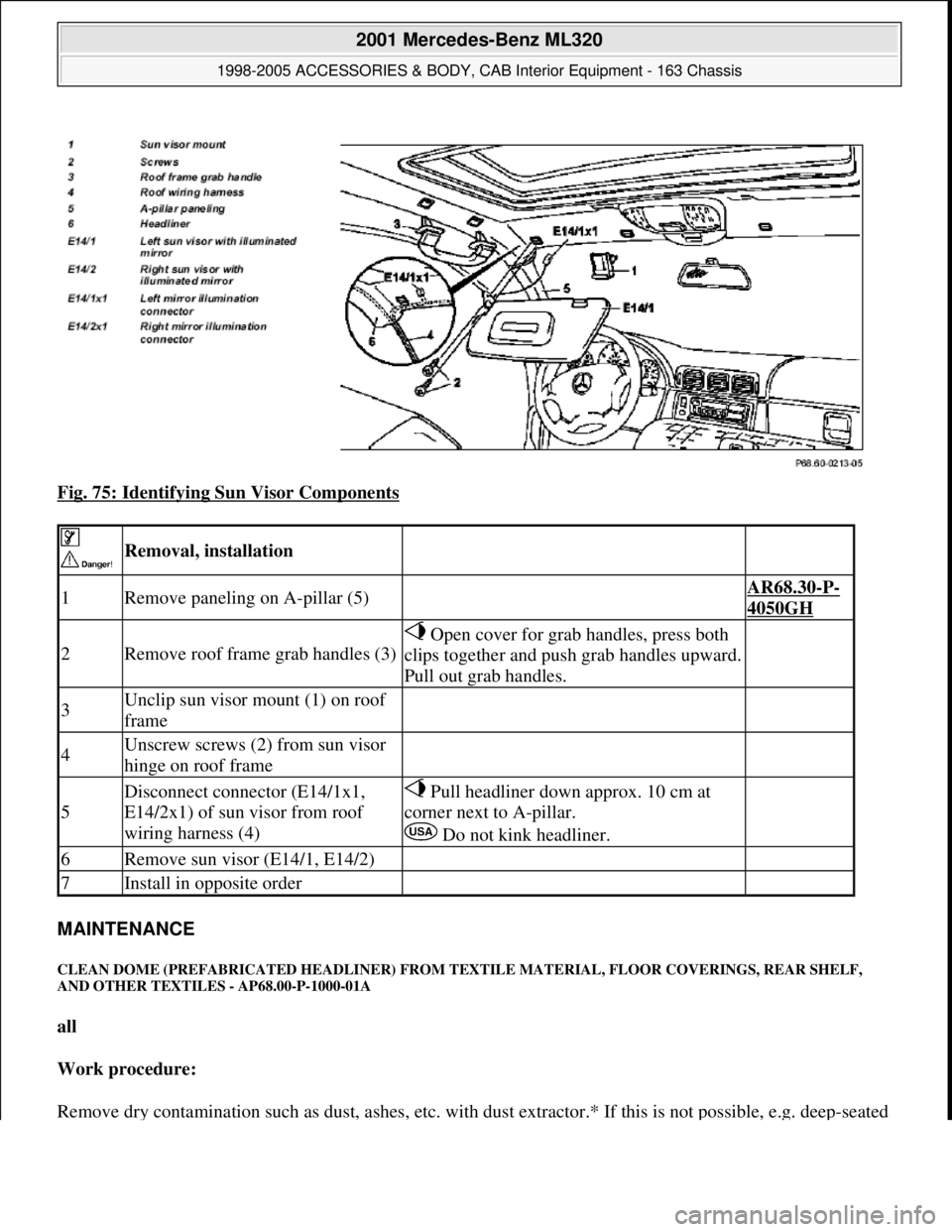
Fig. 75: Identifying Sun Visor Components
MAINTENANCE
CLEAN DOME (PREFABRICATED HEADLINER) FROM TEXTILE MATERIAL, FLOOR COVERINGS, REAR SHELF,
AND OTHER TEXTILES - AP68.00-P-1000-01A
all
Work procedure:
Remove dr
y contamination such as dust, ashes, etc. with dust extractor.* If this is not possible, e.g. deep-seated
Removal, installation
1Remove paneling on A-pillar (5) AR68.30-P-
4050GH
2Remove roof frame grab handles (3)
Open cover for grab handles, press both
clips together and push grab handles upward.
Pull out grab handles.
3Unclip sun visor mount (1) on roof
frame
4Unscrew screws (2) from sun visor
hinge on roof frame
5
Disconnect connector (E14/1x1,
E14/2x1) of sun visor from roof
wiring harness (4) Pull headliner down approx. 10 cm at
corner next to A-pillar.
Do not kink headliner.
6Remove sun visor (E14/1, E14/2)
7Install in opposite order
2001 Mercedes-Benz ML320
1998-2005 ACCESSORIES & BODY, CAB Interior Equipment - 163 Chassis
me
Saturday, October 02, 2010 3:35:22 PMPage 74 © 2006 Mitchell Repair Information Company, LLC.
Page 3597 of 4133
Fig. 77: Identifying D-Pillar Paneling, Template And Oblong Hole
MODIFY ROOF PANELING FOR INSTALLING HANDLE AND CLAMPING STRAP MOUNT - AN68.30-P-0001-02A
Model 163.113 /154 #A up to 289564, #X up to 754619 Model 163.136/ 172 with code (847), 3rd seat row
Handles
1. Remove clothes hook and accessory hook.
2. Position template (1) to roof paneling.
Fasten template with adhesive tape.
3. Mark points which must be cut out for installing the handle.
4. Remove template (1).
5. Cut out cutouts for handle.
NumberDesignationMODEL Series 163
BA68.70-P-1001-02AScrew for pivot handle/mount on roof frameNm2.5
2001 Mercedes-Benz ML320
1998-2005 ACCESSORIES & BODY, CAB Interior Equipment - 163 Chassis
me
Saturday, October 02, 2010 3:35:22 PMPage 79 © 2006 Mitchell Repair Information Company, LLC.
Page 3598 of 4133
Fig. 78: Identifying Handle Template
Only on vehicles with safety standard FMVSS201.
6.1 Install shock absorber (5).
Danger of cracks. Carefully pull roof paneling downward and install shock absorber between roof
paneling and roof frame.
The flat side of the shock absorber (5) points in the direction of the roof frame.
Fig. 79: Identifying Accessory Hook And Pivot Handle
- Only On Vehicles With Safety Standard
FMVSS201.
7 Install accessory hook (2), clamping strap mount (3) and pivot handle (4).
On vehicles with FMVSS201 install special clamping strap mounts and pivot handles with screws (6)
.
8 Repeat on opposite side.
2001 Mercedes-Benz ML320
1998-2005 ACCESSORIES & BODY, CAB Interior Equipment - 163 Chassis
me
Saturday, October 02, 2010 3:35:22 PMPage 80 © 2006 Mitchell Repair Information Company, LLC.
Page 3599 of 4133
Fig. 80: Identifying Accessory Hook, Clamping Strap Mount And Pivot Handle - On Vehicles With
FMVSS201
MODIFY ROOF PANELING FOR INSTALLING HANDLE AND CLAMPING STRAP MOUNT - AN68.30-P-0001-02B
Model 163.113 /154 #A as of 289565, Model 163.113 #X as of 754620, Model 163.128/ 157/ 175 with code
(847), 3rd seat row
1. Remove accessory hook.
2. Position template (1) to roof paneling.
Fasten template with adhesive tape.
3. Mark points which must be cut out for installing pivot handle and clamping strap.
4. Remove template (1).
Fig. 81: Identifying Pivot Handle Template
5. Cut out cutouts for pivot handle and clamping strap mount.
Do not cut into window airbag or wiring harness.
6. Repeat on opposite side.
2001 Mercedes-Benz ML320
1998-2005 ACCESSORIES & BODY, CAB Interior Equipment - 163 Chassis
me
Saturday, October 02, 2010 3:35:22 PMPage 81 © 2006 Mitchell Repair Information Company, LLC.
Page 3603 of 4133
GF77.20-P-0001-01GH
Electric sliding/pop-up roof (SR), location of
components
P77.20-0380-06
M12
Sliding /pop-up roof drive assembly
S13/2
Sliding /pop-up roof switch
Copyright DaimlerChrysler AG 04.08.2006 CD-Ausgabe G/10/04 . This WIS print-out will not be recorde
d by Modification services.
Page 1
Page 3730 of 4133

GF77.20-P-2003GH
Opening pop-up roof, function
19.2.97
MODEL
163 with CODE (414a) Electric glass sliding/pop-up roof
Function prerequisites
D
Voltage not too low or too high
D
Switch-on conditions for convenience control fulfilled
D
Sliding/pop-up roof synchronized
Function
When
switch (SHD, S13/2)
is actuated continuously, circuit 30 is
switched through to the
sliding/pop-up roof (M12)
and the pop-up
roof opens.
The function "Open pop-up roof" is executed as long as
D
switch (SHD, S13/2)
is actuated and
D
the pop-up roof has not yet reached the end position and
D
lock-up is not recognized.
If the sliding/pop-up roof is desynchronized, it moves only in the pop-
up roof direction each time the
switch (SHD, S13/2)
is actuated. This
means that it is possible to move to the zero
position for synchronizing. After successful
synchronization
, the
sliding/pop-up roof can be controlled again without limitation.
Vehicles
up to 11.99:
The power for the
sliding/pop-up roof (M12)
is supplied via a
fuse directly to c. 30.
The power for the
switch (SR, S13/2)
is supplied via the
convenience relay (F1k14)
, which is actuated by the all-
activity module (AAM, N10).
Vehicles
as of 12.99:
The power for the
sliding/pop-up roof (M12)
is supplied via a
fuse directly to c. 30. The power for the
switch (SHD, S13/2) is
supplied via a lead to the
extended-activity module (EAM,
N10/1) , this power is switched through only when the switch-on
conditions for the convenience control are fulfilled and the EAM
is coded accordingly.
Closing sliding /pop-up roof, function
GF77.20-P-2002GH
Sliding /pop-up roof lock-up recognition,
function
GF77.20-P-3000GH
Sliding /pop-up roof position measurement,
function
GF77.20-P-3001GH
Synchronizing sliding /pop-up roof, function
GF77.20-P-3002GH
Convenience control
GF72.29-P-2002GH
All-activity module (AAM)
up to 11.99
GF54.21-P-4100GH
Extended-activity module, location/
purpose/design/function
as of 12.99
GF54.21-P-4107GK
Copyright DaimlerChrysler AG 04.08.2006 CD-Ausgabe G/10/04 . This WIS print-out will not be recorde
d by Modification services.
Page 1
Page 3735 of 4133
AR77.20-P-0001GH
Removing and installing switch for pop-up/sliding roof
29.4.97
MODEL
163 with CODE (414a) Electric glass pop-up/sliding roof
P77.20-0449-11
1
Overhead control panel
2
Screws
S13/2
Sliding/pop-up roof switch
X18/2
Interior/roof connector
Operation no. of operation texts or of standard texts and flat rates
Division
Operation
no.
Operation text
P
772650
REPLACING CONTROL SWITCH FOR SLIDING ROOF DRIVE
P
825602
REMOVING AND INSTALLING FRONT INTERIOR LAMP (1), REPLACING ACCORDING TO CONDITION
Removal, installation
1
Remove overhead control panel (1)
AR82.20-P-1100GH
2
Remove sliding/pop-up roof switch (S13/2)
from overhead control panel control module (1)
Unscrew screws (2) from overhead
control panel (1)
3
Disconnect connector (X18/2)
4
Install in opposite order
Copyright DaimlerChrysler AG 09.05.2006 CD-Ausgabe G/10/04 . This WIS print-out will not be recorde
d by Modification services.
Page 1
Page 3736 of 4133

AR82.20-P-1100GH
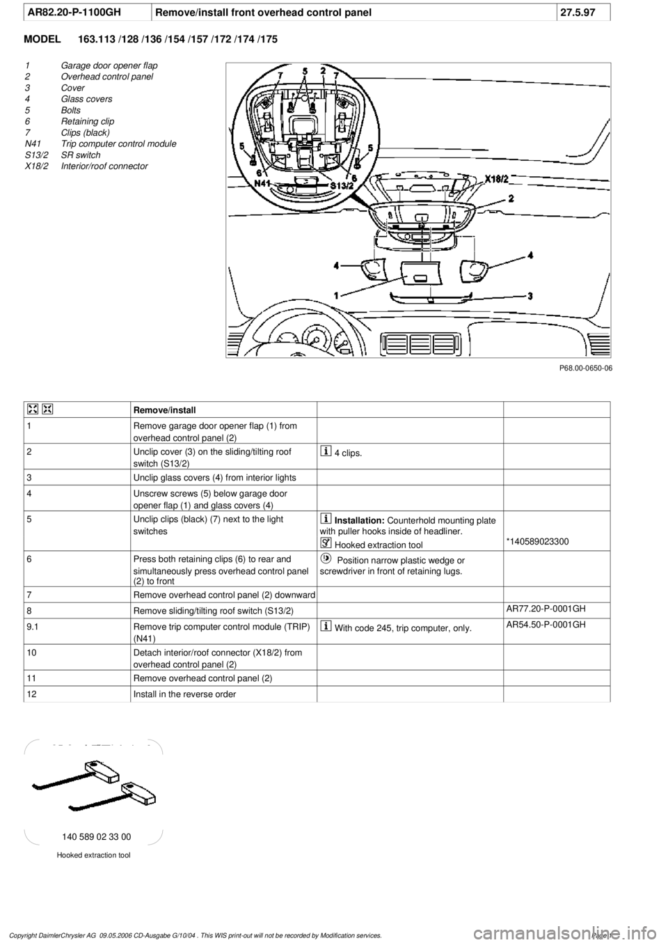
Remove/install front overhead control panel
27.5.97
MODEL
163.113 /128 /136 /154 /157 /172 /174 /175
P68.00-0650-06
1
Garage door opener flap
2
Overhead control panel
3
Cover
4
Glass covers
5
Bolts
6
Retaining clip
7
Clips (black)
N41
Trip computer control module
S13/2
SR switch
X18/2
Interior/roof connector
Remove/install
1
Remove garage door opener flap (1) from
overhead control panel (2)
2
Unclip cover (3) on the sliding/tilting roof
switch (S13/2)
4 clips.
3
Unclip glass covers (4) from interior lights
4
Unscrew screws (5) below garage door
opener flap (1) and glass covers (4)
5
Unclip clips (black) (7) next to the light
switches
Installation:
Counterhold mounting plate
with puller hooks inside of headliner.
Hooked extraction tool
*140589023300
6
Press both retaining clips (6) to rear and
simultaneously press overhead control panel
(2) to front
Position narrow plastic wedge or
screwdriver in front of retaining lugs.
7
Remove overhead control panel (2) downward
8
Remove sliding/tilting roof switch (S13/2)
AR77.20-P-0001GH
9.1
Remove trip computer control module (TRIP)
(N41)
With code 245, trip computer, only.
AR54.50-P-0001GH
10
Detach interior/roof connector (X18/2) from
overhead control panel (2)
11
Remove overhead control panel (2)
12
Install in the reverse order
Hooked extraction tool
140 589 02 33 00
Copyright DaimlerChrysler AG 09.05.2006 CD-Ausgabe G/10/04 . This WIS print-out will not be recorde
d by Modification services.
Page 1