Page 3788 of 4133

AF77.20-P-2005A
Seal on sliding/pop-up roof gutter loosens
28.6.00
MODEL
163.113 /136 /154 /172 /174 with CODE (414a) Electric glas sliding/pop-up roof
Modification notes
15.11.00
Damage code added
Damage code
Cause
Remedy
The seal on the sliding/pop-up roof loosens
when the sliding/pop-up roof moves
1
Remove sliding/pop-up roof
AR77.20-P-1000GH
2
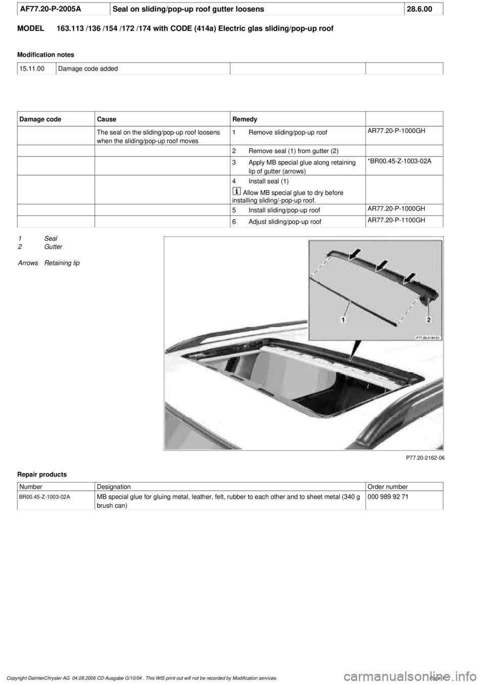
Remove seal (1) from gutter (2)
3
Apply MB special glue along retaining
lip of gutter (arrows)
*BR00.45-Z-1003-02A
4
Install seal (1)
Allow MB special glue to dry before
installing sliding/-pop-up roof.
5
Install sliding/pop-up roof
AR77.20-P-1000GH
6
Adjust sliding/pop-up roof
AR77.20-P-1100GH
P77.20-2162-06
1
Seal
2
Gutter
Arrows
Retaining lip
Repair products
Number
Designation
Order number
BR00.45-Z-1003-02A
MB special glue for gluing metal, leather, felt, rubber to each other and to sheet metal (340 g
brush can)
000 989 92 71
Copyright DaimlerChrysler AG 04.08.2006 CD-Ausgabe G/10/04 . This WIS print-out will not be recorde
d by Modification services.
Page 1
Page 3815 of 4133

AR91.40-P-2000GHRemove/install seat belts for third row of seats
12.3.97
MODEL
163.113 /128 /136 /154 /157 /172 /175 with CODE (847) 3rd seat row
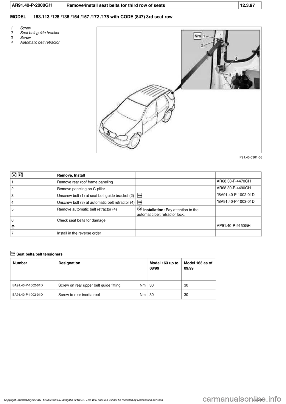
P91.40-0361-06
1
Screw
2
Seat belt guide bracket
3
Screw
4
Automatic belt retractor
Remove, Install
1
Remove rear roof frame paneling
AR68.30-P-4470GH
2
Remove paneling on C-pillar
AR68.30-P-4490GH
3
Unscrew bolt (1) at seat belt guide bracket (2)
*BA91.40-P-1002-01D
4
Unscrew bolt (3) at automatic belt retractor (4)
*BA91.40-P-1003-01D
5
Remove automatic belt retractor (4)
Installation:
Pay attention to the
automatic belt retractor lock.
6
Check seat belts for damage
e
AP91.40-P-9150GH
7
Install in the reverse order
Seat belts/belt tensioners
Number
Designation
Model 163 up to
08/99
Model 163 as of
09/99
BA91.40-P-1002-01D
Screw on rear upper belt guide fitting
Nm
3030
BA91.40-P-1003-01D
Screw to rear inertia reel
Nm
3030
Copyright DaimlerChrysler AG 14.06.2006 CD-Ausgabe G/10/04 . This WIS print-out will not be recorde
d by Modification services.
Page 1
Page 3837 of 4133

GF77.20-P-0001GH
Sliding /pop-up roof, function
28.2.97
MODEL
163 with CODE (414a) Electric glass sliding/pop-up roof
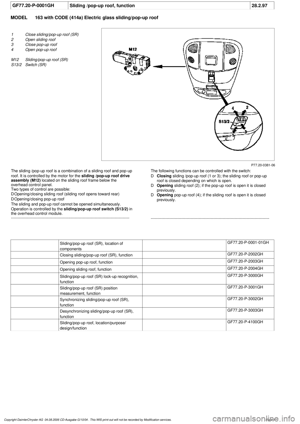
P77.20-0381-06
1
Close sliding/pop-up roof (SR)
2
Open sliding roof
3
Close pop-up roof
4
Open pop-up roof
M12
Sliding/pop-up roof (SR)
S13/2
Switch (SR)
The sliding /pop-up roof is a combination of a sliding roof and pop-up
roof. It is controlled by the motor for the
sliding /pop-up roof drive
assembly (M12)
located on the sliding roof frame below the
overhead control panel.
Two types of control are possible:
D
Opening/closing sliding roof (sliding roof opens toward rear)
D
Opening/closing pop-up roof
The sliding and pop-up roof cannot be opened simultaneously.
Operation is controlled by the
sliding/pop-up roof switch (S13/2)
in
the overhead control module.
-----------------------------------------------------------------------------------------
The following functions can be controlled with the switch:
D
Closing
sliding /pop-up roof (1 or 3); the sliding roof or pop-up
roof is closed depending on which is open.
D
Opening
sliding roof (2); if the pop-up roof is open it is closed
previously.
D
Opening
pop-up roof (4); if the sliding roof is open it is closed
previously.
-----------------------------------------------------------------------------------------
Sliding/pop-up roof (SR), location of
components
GF77.20-P-0001-01GH
Closing sliding/pop-up roof (SR), function
GF77.20-P-2002GH
Opening pop-up roof, function
GF77.20-P-2003GH
Opening sliding roof, function
GF77.20-P-2004GH
Sliding/pop-up roof (SR) lock-up recognition,
function
GF77.20-P-3000GH
Sliding/pop-up roof (SR) position
measurement, function
GF77.20-P-3001GH
Synchronizing sliding/pop-up roof (SR),
function
GF77.20-P-3002GH
Desynchronizing sliding/pop-up roof (SR),
function
GF77.20-P-3003GH
Sliding/pop-up roof, location/purpose/
design/function
GF77.20-P-4100GH
Copyright DaimlerChrysler AG 04.08.2006 CD-Ausgabe G/10/04 . This WIS print-out will not be recorde
d by Modification services.
Page 1
Page 3885 of 4133
Fig. 1: Disconnecting Negative Battery Cable
Courtesy of MERCEDES-BENZ OF NORTH AMERICA.
BASIC PROGRAMMING
1. Code radio. See Coding radio .
2. Set time on instrument cluster. Pull out knob at lowe r right of speedometer. To adjust hour, turn to right.
To adjust minute, turn to left.
3. If necessary, set time at stationary heater timer. See owner's manual.
4. Start engine and run at idle. Turn steering wheel fr om one lock position to the other to activate steering
angle sensor. Center steering wheel. Ma lfunction indicator lamp should go out.
5. If equipped, normalize ti lting/sliding roof. Open sunroof and hold down switch. Sunroof moves to end
position and pulls back 1/4 turn and stops. If equipped with lemella slidin
g roof, close roof and keep
2001 Mercedes-Benz ML320
2001-04 STARTING & CHARGING SYSTEMS Starters - 163 Chassis
me
Saturday, October 02, 2010 3:19:47 PMPage 3 © 2006 Mitchell Repair Information Company, LLC.
Page 3937 of 4133

GF77.20-P-3002GH
Synchronizing sliding /pop-up roof, function
19.2.97
MODEL
163 with CODE (414a) Electric glass sliding/pop-up roof
Synchronization
is necessary to match the counter status of the
position counter with the actual position of the sliding /pop-up roof in
the evaluation electronic module for the
sliding /pop-up roof (M12)
.
Synchronization is required when the
sliding /pop-up roof (M12)
has been disconnected from the power supply or a malfunction has
occurred during position measurement resulting in
desynchronization
.
In the desynchronized state the evaluation electronic module in the
sliding /pop-up roof (M12)
cannot recognize the position of the roof.
-----------------------------------------------------------------------------------------
In this case control is possible only to a limited extent; it is only
possible to open the pop-up roof for synchronization.
Synchronizing
When the
sliding /pop-up roof (M12)
is moved to the mechanical
end position "pop-up roof open" in the desynchronized state, the
evaluation electronic module recognizes that the motor is
locked up
and then performs
synchronization
; the position counter is set to "0"
and the sliding /pop-up roof can then be operated again without
limitations.
-----------------------------------------------------------------------------------------
Closing sliding /pop-up roof, function
GF77.20-P-2002GH
Desynchronizing sliding /pop-up roof, function
GF77.20-P-3003GH
Sliding/pop-up roof, location/purpose/
design/function
GF77.20-P-4100GH
Sliding /pop-up roof lock-up recognition,
function
GF77.20-P-3000GH
Sliding / pop-up roof position measurement,
function
GF77.20-P-3001GH
Copyright DaimlerChrysler AG 04.08.2006 CD-Ausgabe G/10/04 . This WIS print-out will not be recorde
d by Modification services.
Page 1
Page 3983 of 4133

10
Remove edge guard for tilting/sliding roof
cutout
11
Release upper right B-pillar paneling
12
Remove covers at lower rear seat
Do NOT remove center cover for lower
40% seat. Do NOT reinstall curtain on 60%
front bench seat.
f
Remove and install cover on bottom of rear
seat
AR91.12-P-1100GH
13
Release side shade at the 60% bench
Fold shade upward so that the working
area is not obstructed.
14
Remove 40% rear seat
f
Remove and install bench
AR91.12-P-1010GI
Torx bit set
*000589011000
Install
15
Retrofit central interface module (1)
AZ82.60-P-0004-01A
16
Insert antenna cable for FM modulator (6) into
vehicle antenna cable (7)
17
Cover connector with self-adhesive foamed
material (8)
18
Plug remaining antenna cable of FM
modulator (9) into radio
19
Install radio (A2)
f
Remove/install radio
AR82.60-P-7502EA
20
Retrofit video monitor (2) and wiring harness
of video monitor (C)
With
glass version of electric sliding/tilting
roof, code 414a.
AZ82.60-P-0004-02A
Except
glass version of electric
sliding/tilting roof, code 414a.
AZ82.60-P-0004-02B
21
Secure upper right B-pillar paneling
Ensure that the lugs of the seat belt height
adjustment are located correctly in the recess
clearance of the paneling.
22
Install right front handle
23
Install right sun visor
f
Remove/install sun visor
AR68.60-P-5480GH
24
Install right front A-pillar cover
f
Remove/install paneling on A-pillar
AR68.30-P-4050GH
25
Re-secure upper area of rubber door seal
26
Route wiring harness of video/DVD player
(B), additional interface module (4) and wiring
harness of video monitor (C) later
Up to VIN A289564, X754619.
AZ82.60-P-0004-03A
As of VIN A289565, X754620.
AZ82.60-P-0004-03B
27
Retrofit auxiliary interface module (4) in
center console
Up to VIN A289564, X754619.
AZ82.60-P-0004-04A
As of VIN A289565, X754620.
AZ82.60-P-0004-04B
28
Install center console insulating mat
29
Install center console
f
Remove/install center console
AR68.20-P-2000GH
30.1
Plug in plug of additional interface module
and secure the wiring harness of the
additional interface module (10) to the clip
(11) together with the wiring harness of the
rear power windows in the center console
Up to VIN A289564, X754619.
30.2
Insert auxiliary interface module (13)
connector and route between center console
mount (14) and center console.
As of VIN A289565, X754620.
31.1
Secure auxiliary interface module plug in the
left rear corner of the ashtray housing using
self-adhesive foamed material (12)
Up to VIN A289564, X754619.
32
Open ashtray and cup holder and close to
check correct function
33
Attach side shade of the 60% bench
34.1
Retrofit video player (3)
AZ82.60-P-0004-05A
*BA91.12-P-1005-03A
*BA91.12-P-1008-03A
34.2
Retrofit DVD player
AZ82.60-P-0005-01GH
35
Install 40% rear seat
f
Remove and install bench
AR91.12-P-1010GI
Torx bit set
*000589011000
Copyright DaimlerChrysler AG 09.05.2006 CD-Ausgabe G/10/04 . This WIS print-out will not be recorde
d by Modification services.
Page 2
Page 4093 of 4133
Fig. 47: Passenger"s Power Seat Circuit
POWER TOP/SUNROOF
2001 Mercedes-Benz ML320
2001 SYSTEM WIRING DIAGRAMS Mercedes-Benz - ML320
me
Saturday, October 02, 2010 3:28:00 PMPage 95 © 2006 Mitchell Repair Information Company, LLC.
Page 4095 of 4133
Fig. 48: Double Panel Sunroof Circuit
2001 Mercedes-Benz ML320
2001 SYSTEM WIRING DIAGRAMS Mercedes-Benz - ML320
me
Saturday, October 02, 2010 3:28:00 PMPage 97 © 2006 Mitchell Repair Information Company, LLC.